
A Coordinated Electric System Interconnection Review—the utility’s deep-dive on technical and cost impacts of your project.
Challenge: Frequent false tripping using conventional electromechanical relays
Solution: SEL-487E integration with multi-terminal differential protection and dynamic inrush restraint
Result: 90% reduction in false trips, saving over $250,000 in downtime
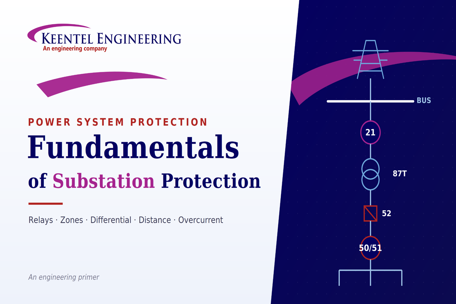
Fundamentals of Substation Protection
Jun 30, 2026 | Blog
Part 1—Understanding Substation Protection from the Ground Up
Why protection exists at all
Every time you flip a switch and a light comes on, you're at the receiving end of a chain that began at a power plant, climbed to hundreds of kilovolts for long-distance transmission, was stepped down at one or more substations, and finally arrived at your premises at a usable voltage. That chain — generation, step-up, transmission, step-down, distribution, delivery — is the power system. It is also, at every point, exposed to faults: insulation that fails, trees that fall across lines, lightning that strikes, animals that bridge a gap, equipment that simply wears out.
When a fault happens, enormous energy concentrates at one spot in milliseconds. Left alone, it damages expensive equipment, starts fires, and can injure or kill people. Power system protection — also called protective relaying — is the discipline that detects these abnormal conditions and removes the affected part of the system quickly and accurately, before the damage spreads.
It is often described as a blend of science, art, and skill: science because it rests on circuit theory and fault analysis, art because two competent engineers can defend different settings, and skill because it is only as good as the person applying and commissioning it. The purpose statement is refreshingly simple and has not changed in a century:
- Prevent injury to personnel.
- Minimize damage to system components.
- Limit the extent and duration of service interruption.
Everything else in this article is detail in service of those three goals.
The four building blocks
Transducers — The instrument transformers, namely current transformers (CTs) and voltage/potential transformers (PTs). The power system runs at thousands of amps and tens of thousands of volts; relays cannot touch those quantities directly. CTs and PTs scale them down to standard, safe levels — typically 5 A and 115 V — that relays are built to measure. They are the senses of the system.
Relays — The brain. A relay continuously watches the scaled-down quantities and decides whether conditions are normal or abnormal. If everything is normal, it does nothing. If a quantity crosses into abnormal territory, it issues a trip signal. That decision — normal or abnormal — is the entire job, and getting it right under every credible condition is the entire challenge.
Circuit breakers —The muscle. When the relay says "trip," the breaker physically interrupts the current and isolates the faulted section. The relay decides; the breaker acts.
Tripping and auxiliary supplies —usually a station battery. This is the detail beginners overlook: protection must work
during a fault, which is precisely when the AC system may have collapsed. A reliable DC battery supply energizes the relay logic and the breaker trip coil independently of the faulted AC system, so the scheme can clear a fault even when the lights are out.
What protection is actually fighting
The abnormalities a substation faces fall into three broad families:
- Overcurrent — overload, short circuit, or open circuit.
- Ground potential — ungrounded equipment, dangerous touch and step potentials.
- Surge voltages — lightning strokes, switching surges, and harmonics.
Of these, short-circuit faults dominate the protection engineer's attention, and not all faults are equally common. The well-known field statistics are worth memorizing because they shape design priorities:
| Fault type | Approx. share of faults |
|---|---|
| Single-line-to-ground (SLG) | ~85% |
| Line-to-line (LL) | ~8% | ~8% |
| Double-line-to-ground (DLG) | ~5% |
| Three-phase (3L) | ~2% or less |
The lesson is immediate: Ground faults are by far the most common, which is why dedicated ground protection (the "N" and "G" functions you'll meet below) earns its place on nearly every feeder and transformer.
Faults are also unevenly distributed across equipment. Roughly half occur on overhead lines, with the remainder spread across switchgear, transformers, cables, instrument transformers, control equipment, and miscellaneous causes. Overhead lines are exposed to the weather and the public, so they fail most — and they are also the hardest to protect because they are long and electrically "fuzzy" at their far ends.
The seven design tensions
There is no such thing as perfect protection, only a defensible balance among competing demands. A good scheme is judged against these criteria:
Reliability is the master quality, and it splits into two halves that pull against each other:
- Dependability — certainty that the relay will operate when it should. A dependable scheme never misses a real fault.
- Security — assurance that the relay will not operate when it shouldn't. A secure scheme never trips on load, transients, or external faults.
You can always make a scheme more dependable by making it more eager to trip, but every step in that direction costs security, and vice versa. Much of the craft of protection is finding the right point on that seesaw for a given application.
Sensitivity — the relay must respond to genuine abnormal conditions, even weak ones (like a high-resistance ground fault), while ignoring normal operating conditions.
Selectivity — when a fault occurs, only the breakers needed to isolate it should open, and no more. This is achieved through the concept of zones of protection, discussed below. Good selectivity means a fault on one feeder does not darken the whole substation.
Speed — faults must be cleared fast, because damage and instability both grow with time. Speed is classified as:
- Instantaneous — no intentional delay.
- High speed — operation in less than about three cycles.
- Time-delay — an intentional delay, deliberately introduced for coordination.
Economics — maximum protection at minimum cost. The price of installing, operating, and maintaining the scheme is always weighed against the potential losses from equipment damage and outages.
Experience — history is a design input. Knowing the kinds of trouble a given system tends to suffer, how relays have actually performed, and how the system is operated and maintained all feed back into better schemes.
Industry standards — bodies such as IEEE and IEC, through ANSI and IEC standards, codify decades of collective experience so that every engineer is not forced to reinvent the basics.
How relays evolved: from spinning discs to software
The hardware that makes the trip decision has gone through three generations, and understanding the progression explains why modern substations look the way they do.
Electromechanical relays (1st generation) were the workhorses for most of the twentieth century. They use the induction-disc principle — the same physics as an old watthour meter. Current through a coil produces torque on a metal disc; the disc rotates against a spring until its contacts close and send a trip. They are robust and intuitive, but they have moving parts that wear, springs that fatigue with temperature, and they need periodic recalibration. They also impose a high burden on CTs and lose sensitivity at higher currents. Their saving grace, the draw-out construction, lets a technician pull the relay for testing without rewiring.
Static / solid-state relays (2nd generation) replaced the spinning disc with electronics. Timing characteristics come from RC circuits rather than a rotating mass, so there are no moving parts, reset is fast, and maintenance drops. They were widely used to retrofit electromechanical units. Their weaknesses live in the analog domain: RC timing drifts with temperature and has poor repeatability, and the AC-to-DC conversion at the front end is vulnerable to offset, harmonics, and noise. RC and LC filters could tame some of that, but at the cost of slower tripping.
Digital and numerical relays (3rd generation) are computers. A microprocessor or microcontroller samples the waveform, converts it to numbers, and applies digital signal processing to extract exactly the information it needs. The consequences are transformative:
- Selectable characteristics and functions — one relay can be configured for many protection roles.
- Metering and control built in.
- Event and disturbance recording, enabling true post-mortem analysis of a fault.
- Remote communication to laptops and control centers.
- Self-monitoring — the relay watches its own health.
- "All in one" — a single numerical relay can replace a panel full of discrete relays.
Numerical relays bring inherent immunity to DC offset and harmonics through tuned digital filtering, highly stable and repeatable performance, very few physical components, and the ability to act as a full bay-level controller rather than a mere protection element. The one nuance worth remembering from signal processing: a pure time-domain sample stream carries amplitude but, by itself, no phase or frequency information — which is exactly why the digital filtering and measurement algorithms inside the relay matter so much.
Zones, overlap, and the no-blind-spot rule
The single most important organizing idea in protection is the zone of protection a defined region of the power system that a given set of relays is responsible for. Two rules govern zones:
- Every element of the power system must lie inside at least one zone. Nothing may be left unprotected.
- Adjacent zones must overlap. If they merely touched, a fault exactly at the boundary could fall into a gap. Overlapping the zones typically arranged around the circuit breakers and their CTsv guarantees there are no "blind spots."
A typical substation is carved into zones such as bus protection, transformer protection, line (subtransmission) protection, feeder protection, and generator protection. The overlap is deliberately built at the breakers, so that whichever zone sees the fault, the boundary itself is always covered twice.
Primary and backup: assume the first line will sometimes fail
No component is perfect, so protection is layered.
Primary protection is the main scheme for a zone — the first to act, ideally fast and selective.
Backup protection stands ready in case the primary fails to clear the fault (a stuck breaker, a failed relay, a lost DC supply). Backup comes in two forms:
- Local backup — alternate protection at the same substation, which trips additional local breakers if the primary device fails.
- Remote backup — protection at neighboring substations that reaches into this zone and clears the fault from the far end if the local scheme fails entirely.
Remote backup is slower and trips more of the system, but it works even if the entire local substation's protection or DC supply is lost — a genuinely independent layer.
How relays tell faults apart: methods of discrimination
For protection to be selective, relays must distinguish a fault they should clear from one they should leave to someone else. They do it using one or more of these handles:
- Current magnitude — a fault closer to the source draws more current; grading pickup levels lets relays sort near from far.
- Time — deliberately delaying downstream-versus-upstream relays so the device closest to the fault acts first.
- Current direction — knowing which way fault current is flowing, so a relay only responds to faults in front of it.
- Distance (impedance) measurement — computing Z = V/I, which is proportional to the distance to the fault.
- Current balance — comparing current in versus current out of a protected zone (the basis of differential protection).
- Phase comparison — comparing the phase of currents at the two ends of a line.
Real schemes combine these. Time plus current magnitude gives the classic inverse-time overcurrent grading. Time plus distance gives the stepped, multi-zone reach of distance relays. Current balance gives differential protection its near-perfect selectivity.
The standard relay types you will meet
Protection engineering speaks in ANSI device numbers — a shorthand where each function has a number. A few you will see constantly: 50 instantaneous overcurrent, 51 AC time overcurrent, 52 the circuit breaker itself, 87 differential, 21 distance, 67 directional overcurrent, 79 auto-reclosing, 86 lockout, and the N or G suffix for the ground version of a function. Here are the workhorses behind the numbers.
Overcurrent relays (50/51) operate when current exceeds a preset value. They are simple and non-directional. On a radial feeder, you typically need three phase relays plus one ground relay — the ground relay (51N) measures the residual current, the sum of the three phase currents, which is zero in healthy balanced operation and nonzero the instant a ground fault appears.
Directional overcurrent relays (67) add a condition: they only operate for fault current flowing in a defined direction. This makes overcurrent protection usable on looped systems where current can flow either way, and it improves both selectivity and security. Their limit is that as source strengths change, a directional overcurrent relay can be fooled into seeing a fault it shouldn't — which is one reason distance relays are preferred on important lines.
Distance relays (21) measure the impedance of the line. Because line impedance is proportional to length, the relay effectively measures how far away the fault is, independent of source strength. They are the standard for double-ended transmission lines from roughly 69 kV up to 500 kV. Their characteristic shapes — impedance, reactance, mho, quadrilateral, composite — are plotted on the R-X plane, and the mho characteristic dominates in practice because it is inherently directional.
Differential relays (87) apply the simplest and most powerful idea in protection:
what goes in must come out. They compare the current entering a protected element with the current leaving it. In healthy operation, or for a fault
outside the protected zone, the two are equal and the relay sees nothing. For a fault
inside the zone, the balance breaks and the relay trips. Differential protection is beautifully selective because it responds only to faults within its own boundaries — making it the protection of choice for transformers (87T), buses (87B), and generators.
Putting it together: standard substation schemes
The theory becomes concrete in the handful of schemes that protect almost everything in a distribution or subtransmission substation.
Radial line / feeder protection. A radial feeder is fed from one end, so simple overcurrent protection suffices. The standard package is instantaneous and time overcurrent for both phase and ground (50/51 and 50N/51N), a power circuit breaker (52), and an auto-recloser (79) with its recloser switch (43R). Reclosing matters because most overhead-line faults are transient — a branch brushing a conductor, a flashover that clears itself. The recloser trips, waits, and recloses; if the fault was temporary, service is restored automatically, and only a permanent fault results in a lockout.
Looped line protection. Lines that are fed from both ends cannot rely on plain overcurrent, because fault current can arrive from either direction. The standard package centers on a distance relay (21 for phase, 21G for ground), backed up by directional overcurrent (67/67N), with teleprotection (85) and auto-reclosing (79). The distance relay is applied as a stepped, time-graded scheme:
Zone 1 — Set to about 80–90% of the line impedance, no intentional delay. It deliberately under-reaches the far end so it can never mistakenly trip for a fault on the next line. Speed with guaranteed selectivity.
Zone 2 — Set to 100% of the line plus 20–50% of the shortest adjacent line, with a delay of around 0.35 s. It over-reaches to cover the far end of the line that Zone 1 left out, but its delay lets the adjacent Zone 1 act first for faults beyond the bus.
Zone 3 — Reaches still further (100% of the line + 100% of the longest adjacent line + a margin), with about a 1.0 s delay, serving as remote backup. Crucially, its reach must stay above the heaviest load impedance, or it will trip on load.
That stepped scheme leaves one awkward gap: a fault in the last 10–20% of the line is in Zone 1 from the remote end (instantaneous) but only Zone 2 from the local end (delayed) — so one end clears fast and the other lingers. The fix is communication-aided protection (for example, a permissive overreaching transfer trip, POTT): the two ends exchange a signal so that when both ends agree the fault is on the protected line, both trip instantaneously. Add single-shot auto-reclosing (around 300 ms, to give the breaker time to extinguish the arc) and the line is both fast and selective end to end. Note one safety rule: when a trip comes from backup protection rather than the main distance scheme, auto-reclosing is blocked — you don't reclose onto a fault your primary protection couldn't even see properly.
Transformer protection. Transformers are expensive, slow to replace, and vulnerable to both electrical and thermal stress. The threats and their defenses:
Internal faults → differential protection (87T), often with a percentage-restraint characteristic so it stays stable during through-faults and inrush while still catching genuine internal faults.
Overload / external fault backup → time overcurrent (51) and backup ground (51G/151G). Overcurrent relaying is standard for transformers of roughly 5 MVA and above; smaller distribution transformers often just use fuses. The overcurrent characteristic must sit below the transformer's damage curve but above its magnetizing inrush, so it protects the unit without nuisance-tripping every time it energizes.
Overheating → thermal relay. The rule of thumb is sobering: normal maximum working temperature is about 95 °C, and every 8–10 °C of sustained rise above rating roughly halves the transformer's insulation life.
Internal gas / incipient faults → Buchholz relay, which detects gas generated by an internal arc.
Sudden internal pressure → sudden-pressure relay / pressure relief.
A lockout relay (86T) ties it together: when 87T operates, the lockout trips and locks out both the high-side and low-side breakers, and they cannot be reclosed until someone investigates and manually resets.
Busbar protection. A bus fault is potentially the worst event in a substation because everything connects to the bus. Schemes follow the bus arrangement:
- Single bus, double bus / double breaker, breaker-and-a-half, main-and-transfer with single breaker, and ring bus each have their own differential connection. When the bus differential (87B) operates, a lockout (86B) trips and locks out all breakers connected to that bus.
- A vital wiring rule: all CTs feeding a bus differential must have the same ratio, or the scheme will see a false differential current under normal load.
- The ring bus is the elegant exception — it needs no dedicated bus differential at all, because each bus section is already covered by the line or transformer protection on either side of it.
Two technologies implement bus differential:
- Low-impedance schemes use time-overcurrent relays — inexpensive, but vulnerable to CT saturation, so they suit lower-voltage applications (around 34.5 kV and below).
- High-impedance schemes use overvoltage relays and deliberately load the CTs with a high impedance, forcing the differential current to reveal itself as a voltage. They cost more but deliver much higher security, which is why they dominate at 115 kV and above, and on any lower-voltage bus where security is paramount.
The throughline
Strip away the device numbers and the scheme diagrams, and
substation protection is one repeated idea applied at every level: define a zone, give it a fast and selective primary scheme, give it an independent backup, make adjacent zones overlap, and balance dependability against security for the realities of that particular system. The hardware has marched from spinning discs to self-monitoring computers, but the philosophy — clear the fault, protect the people, save the equipment, keep the lights on everywhere the fault
isn't — is exactly what it was at the start.
Part 2 — Case Studies
The following case studies are illustrative and generalized. No project names or locations are identified; each is a composite scenario drawn from common substation-protection situations, presented to show how the fundamentals are applied in practice.
Case Study 1 — A transformer differential that kept tripping on energization
The situation
A distribution substation commissioned a power transformer rated well above the 5 MVA threshold, protected by a percentage differential relay (87T) with backup overcurrent (51) and backup ground (151G). During commissioning, every attempt to energize the transformer from the high side caused the differential relay to operate and lock out through the 86T lockout, even though no fault existed.
The investigation
The protection engineers walked the problem back through the fundamentals. A differential relay trips on the difference between current in and current out. With the transformer unloaded and healthy, that difference should be essentially zero yet the relay was seeing a large transient differential at the exact moment of energization. The signature pointed to magnetizing inrush:
when a transformer is first energized, it draws a brief, large, distorted current to magnetize its core, and that current enters the transformer without a corresponding current leaving the other side. To a naive differential element, inrush looks exactly like an internal fault.
The resolution
The fix followed directly from transformer-protection principles. The relay's settings were reviewed against two boundaries it must respect: the operating characteristic has to sit below the transformer damage curve but above the magnetizing inrush. The percentage-restraint characteristic and the relay's inrush-restraint (harmonic-based) feature were configured so the element would ride through the inrush transient while remaining fully sensitive to genuine internal faults. After the restraint was correctly set, energization proceeded cleanly, and a subsequent staged internal-fault test confirmed the relay still operated correctly for real faults.
The lesson
Differential protection is only as good as its ability to distinguish the kinds of unbalance that are normal (inrush, through-fault CT mismatch) from the kind that is not (an internal fault). The dependability security balance is not abstract here: a relay set purely for maximum dependability would trip on every energization, while one set for the restraint the transformer actually needs is both secure during inrush and dependable during fault.
Case Study 2 — The far-end fault that cleared slowly
The situation
A subtransmission line fed from both ends was protected by stepped distance relays (21) at each terminal, with directional overcurrent backup (67/67N) and auto-reclosing (79). Operators noticed a recurring pattern: for faults near one end of the line, the near breaker tripped instantly, but the far breaker took noticeably longer long enough that the disturbance was more severe than it should have been, and reclosing behavior was inconsistent.
The investigation
This is the classic limitation of a purely stepped distance scheme, and the engineers recognized it immediately. Zone 1 at each terminal is deliberately set to under-reach about 80–90% of the line so that it can trip with no intentional delay while being physically incapable of overreaching into the adjacent line. The consequence is a band near each end of the line (the last 10–20%) that the remote terminal sees in instantaneous Zone 1 but the local terminal sees only in time-delayed Zone 2, roughly 0.35 s later. So a fault in that band clears fast from one end and slow from the other precisely the symptom observed.
The resolution
The remedy was communication-aided protection. A permissive overreaching transfer trip (POTT) scheme was implemented over the existing teleprotection channel (85). With it, each terminal's overreaching zone, upon detecting a fault, sends a permissive signal to the other end; when both ends confirm the fault lies on the protected line, both terminals trip instantaneously, eliminating the delayed-end problem. The single-shot auto-recloser (about 300 ms) was retained for the now-symmetrical fast trips, with the standing rule preserved that backup-initiated trips block reclosing.
The lesson
Stepped distance protection is selective and fast for most of a line but inherently leaves an end-zone timing gap. Recognizing that the slow far-end clearance was a designed-in characteristic, not a relay defect, pointed straight to the correct fix. Communication does not replace the distance relays; it coordinates the two ends so the whole line is covered at high speed.
Case Study 3 — Choosing a busbar protection scheme for a security-critical bus
The situation
A substation upgrade required dedicated busbar protection for an important bus operating above the lower-voltage tier. The original design proposal reused an inexpensive low-impedance differential scheme based on time-overcurrent relays the same approach used elsewhere in the facility on lower-voltage buses. The protection review flagged a concern about its suitability for this particular bus.
The investigation
The reviewers returned to first principles of bus differential protection. A bus differential sums the currents of every circuit on the bus and operates on any imbalance; its great vulnerability is CT saturation during a heavy external (through) fault, when one CT may saturate and produce a false differential current that the scheme misreads as an internal bus fault. Low-impedance, overcurrent-based schemes are economical but are precisely the type most exposed to that failure mode acceptable at the lower-voltage tier (around 34.5 kV and below) where the review confirmed it was appropriately used, but a security risk on a higher-voltage, security-critical bus. The team also verified the wiring fundamental: every CT feeding the differential had to share the same ratio, or the scheme would see a standing false differential even under healthy load.
The resolution
For the critical bus, the design was changed to a high-impedance differential scheme using an overvoltage relay. By deliberately loading the CTs with a high impedance, the scheme forces differential current to manifest as a voltage and is far more tolerant of CT saturation, delivering the higher security the bus warranted consistent with standard practice of applying high-impedance schemes at 115 kV and above and on any lower-voltage bus that demands high security. CT ratios were standardized across all bus circuits, and the bus lockout (86B) was confirmed to trip and lock out every breaker on the bus. The existing low-impedance scheme was retained where it was genuinely appropriate, on the lower-voltage buses.
The lesson
Scheme selection is an exercise in matching the protection to the consequence of failure. The cheaper low-impedance scheme was not "wrong" it was wrong *for this bus*. Letting the security requirement and the CT-saturation risk drive the choice, rather than defaulting to the familiar low-cost option, is the economics-versus-security balance applied with judgment.
Frequently Asked Questions
Q: What is the difference between protection and control?
Control operates equipment under normal conditions — opening and closing breakers on command, regulating voltage, switching capacitor banks. Protection acts under *abnormal* conditions, automatically and within cycles, to isolate faults. Modern numerical relays blur the line by doing both, acting as bay-level controllers, but the protective function remains the one that must work autonomously during a fault.
Q: Why do relays use 5 A and 115 V instead of the real system values?
The power system operates at currents and voltages far too large and dangerous to feed into a relay directly. Current transformers and potential transformers scale those quantities down to standardized, safe secondary values — commonly 5 A and 115 V — that relays are designed and calibrated to measure. This standardization also lets relays from different applications share a common interface.
Q: What is the single most common type of fault, and why does it matter?
The single-line-to-ground (SLG) fault, at roughly 85% of all faults. It matters because it drives design priorities: every feeder and transformer carries dedicated ground-fault protection (the N and G functions) precisely because ground faults so dominate the statistics.
Q: What is the difference between dependability and security?
They are the two halves of reliability. Dependability is the certainty that the relay *will* operate for a genuine fault — never missing one. Security is the assurance that it will *not* operate when it shouldn't — never tripping on load or external disturbances. The two trade off against each other: making a scheme more eager to trip improves dependability but costs security, and vice versa.
Q: What is a "zone of protection," and why must zones overlap?
A zone is the region of the system that a particular set of relays is responsible for. Zones must overlap — usually arranged around the breakers and their CTs — so that no point in the system falls into a gap between two zones. If zones merely touched, a fault exactly on the boundary could go undetected. Overlap guarantees there are no blind spots.
Q: What is the difference between primary and backup protection?
Primary protection is the main scheme that acts first for a given zone. Backup protection stands ready in case the primary fails — for example, a stuck breaker or a failed relay. Backup is either *local* (additional breakers tripped at the same substation) or *remote* (protection at neighboring substations reaching in to clear the fault from the far end).
Q: When should I use overcurrent protection versus distance protection?
Overcurrent (50/51) suits radial circuits fed from one end, where fault current always flows one way and grading by current and time is straightforward. Distance protection (21) suits lines fed from both ends, where current can flow either way: by measuring impedance it gauges how far away the fault is, independent of source strength, giving fast and selective coverage that plain overcurrent cannot.
Q: Why are directional relays needed?
On looped or double-fed systems, fault current can approach a relay from either direction. A plain overcurrent relay cannot tell a fault it should clear from one behind it that it should ignore. Adding directional control (turning 50/51 into 67/67N) lets the relay respond only to faults in front of it, restoring selectivity and improving security.
Q: How does differential protection achieve such precise selectivity?
It compares current entering a protected element with current leaving it. For normal load or any fault *outside* the zone, in equals out and the relay stays silent. Only a fault *inside* the zone unbalances the comparison and trips the relay. Because it responds solely to what happens between its own CTs, it is inherently selective and needs no time coordination with neighbors — which is why it protects transformers, buses, and generators.
Q: What does "percentage restraint" mean on a transformer differential relay?
It is a characteristic that raises the relay's operating threshold in proportion to the through-current. This keeps the relay stable during heavy external (through) faults and during magnetizing inrush — situations that can produce apparent differential current from CT mismatch — while remaining sensitive to genuine internal faults. A variable-slope version steepens the restraint further at high currents for even greater security.
Q: Why must a transformer overcurrent curve sit below the damage curve but above inrush?
Below the damage curve so the relay trips before the fault current can harm the transformer. Above the magnetizing inrush so the relay does not nuisance-trip every time the transformer is energized, since inrush briefly looks like a large overcurrent. The setting has to thread the needle between those two boundaries.
Q: What are the three distance-relay zones for, in plain terms?
Zone 1 is fast and under-reaching (about 80–90% of the line, no delay) so it can trip instantly without ever overreaching into the next line. Zone 2 over-reaches to cover the far end Zone 1 left out, with a short delay (about 0.35 s) so adjacent fast protection acts first where appropriate. Zone 3 reaches further still, with about a 1.0 s delay, as remote backup — and must be set above maximum load so it never trips on load.
Q: Why is communication-aided protection needed if distance relays already exist?
Stepped distance protection leaves a portion of the line (the last 10–20%) where one end clears instantaneously while the other end only sees it in delayed Zone 2. Communication lets both ends exchange a signal (for example, a permissive overreaching transfer trip) so that when both agree the fault is on the protected line, both trip instantaneously — closing the gap.
Q: Why does the system reclose automatically after tripping?
Most overhead-line faults are transient — a branch, a bird, a flashover that clears itself once the line de-energizes. Auto-reclosing (79) trips, waits briefly, then recloses; if the fault has cleared, service is restored automatically. Only a permanent fault leads to a lockout. Reclosing is typically single-shot with a short delay (around 300 ms) to give the breaker time to extinguish the arc, and it is blocked when the trip came from backup protection.
Q: What does a lockout relay (86) do?
When a major protection function operates — a transformer or bus differential, say — the lockout relay trips and *locks out* all the relevant breakers, preventing them from being reclosed until someone investigates the cause and manually resets the device. It is a deliberate barrier against re-energizing onto a serious fault.
Q: Why must all CTs on a bus differential have the same ratio?
A bus differential sums the currents of every circuit on the bus, expecting them to balance to zero under normal load. If the CTs have different ratios, their scaled secondary currents won't cancel even when the primary currents do, producing a false differential that could trip the bus. Matching ratios keeps the comparison valid.
Q: When do I choose a high-impedance bus differential over a low-impedance one?
Low-impedance schemes use time-overcurrent relays and are inexpensive but susceptible to CT saturation, so they fit lower-voltage buses (around 34.5 kV and below). High-impedance schemes use overvoltage relays, resist CT saturation, and offer much higher security — so they are standard at 115 kV and above, and anywhere a lower-voltage bus demands high security.
Q: Why doesn't a ring bus need its own differential protection?
In a ring bus, each bus section sits between the protections of the lines or transformers connected on either side. Those existing zone protections already encompass the bus sections, so a dedicated bus differential is redundant.
Q: Are old electromechanical relays still acceptable?
They still function and remain in service in many substations, prized for ruggedness and simplicity. But they have moving parts that wear, need periodic recalibration, impose a high burden on CTs, and offer none of the metering, recording, communication, or self-monitoring of numerical relays. New installations and major refurbishments almost always favor numerical relays for those reasons.
Q: What's the difference between a digital relay and a numerical relay?
Both are computer-based. "Digital" broadly denotes microprocessor- or microcontroller-based relays with selectable functions, recording, and communication. "Numerical" emphasizes the signal-processing heart: sampling the waveform, converting to digital, then applying numeric filtering and measurement algorithms. In everyday use the terms overlap heavily; numerical is the more precise description of how the modern relay actually computes.
Q: What is a bay-level controller?
A modern numerical relay does so much more than trip that it effectively manages an entire substation "bay" — protection, metering, control, recording, and communication in one device — rather than acting as a single-purpose protection element. That expanded role is what "bay-level controller" describes.

About the Author:
Sonny Patel P.E. EC
IEEE Senior Member
In 1995, Sandip (Sonny) R. Patel earned his Electrical Engineering degree from the University of Illinois, specializing in Electrical Engineering . But degrees don’t build legacies—action does. For three decades, he’s been shaping the future of engineering, not just as a licensed Professional Engineer across multiple states (Florida, California, New York, West Virginia, and Minnesota), but as a doer. A builder. A leader. Not just an engineer. A Licensed Electrical Contractor in Florida with an Unlimited EC license. Not just an executive. The founder and CEO of KEENTEL LLC—where expertise meets execution. Three decades. Multiple states. Endless impact.
Services

Let's Discuss Your Project
Let's book a call to discuss your electrical engineering project that we can help you with.
About the Author:
Sonny Patel P.E. EC
IEEE Senior Member
In 1995, Sandip (Sonny) R. Patel earned his Electrical Engineering degree from the University of Illinois, specializing in Electrical Engineering . But degrees don’t build legacies—action does. For three decades, he’s been shaping the future of engineering, not just as a licensed Professional Engineer across multiple states (Florida, California, New York, West Virginia, and Minnesota), but as a doer. A builder. A leader. Not just an engineer. A Licensed Electrical Contractor in Florida with an Unlimited EC license. Not just an executive. The founder and CEO of KEENTEL LLC—where expertise meets execution. Three decades. Multiple states. Endless impact.
Leave a Comment
Thank you for contacting us.
We will get back to you as soon as possible.
We will get back to you as soon as possible.
Oops, there was an error sending your message.
Please try again later.
Please try again later.
Related Posts
By SANDIP R PATEL
•
July 21, 2026
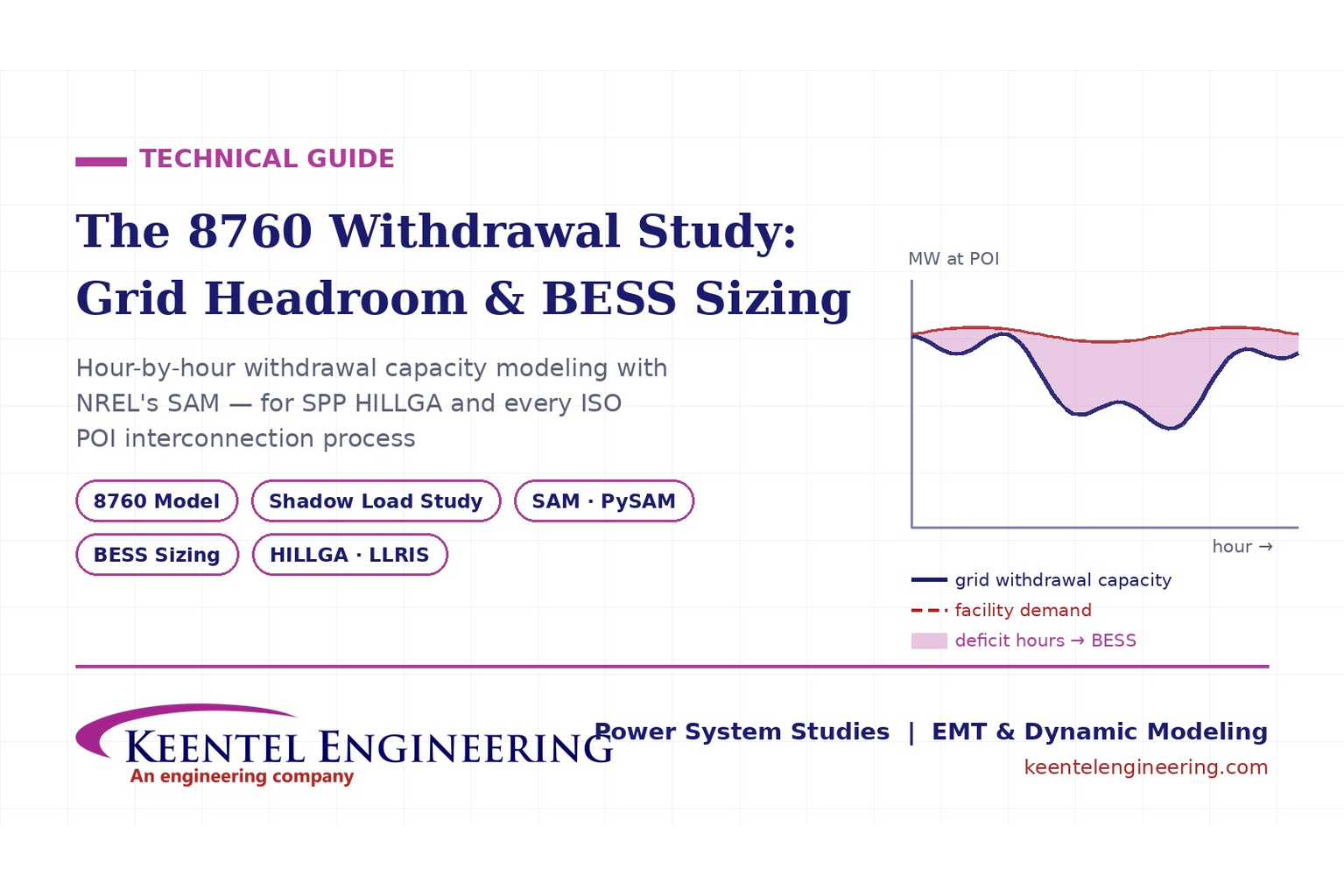
Learn how an 8760 withdrawal study models hourly grid headroom and uses SAM-based BESS sizing for large-load interconnection projects.
By SANDIP R PATEL
•
July 21, 2026
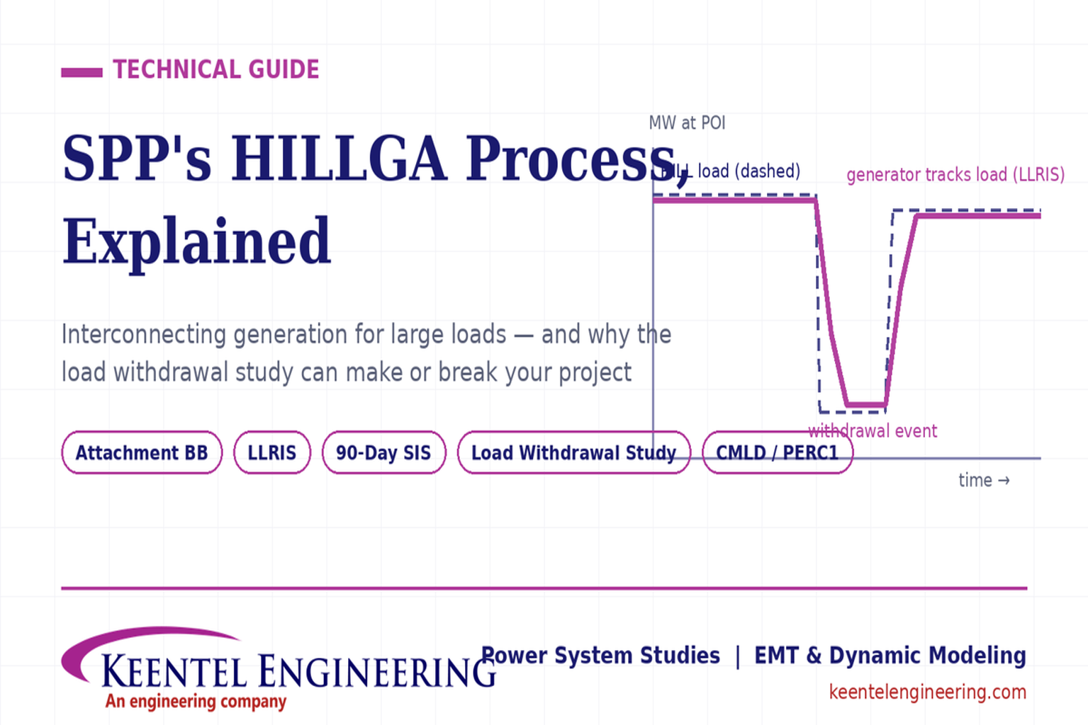
Learn how the SPP HILLGA process supports data center generation interconnection and why an 8760 withdrawal study can determine project success.
By SANDIP R PATEL
•
July 19, 2026
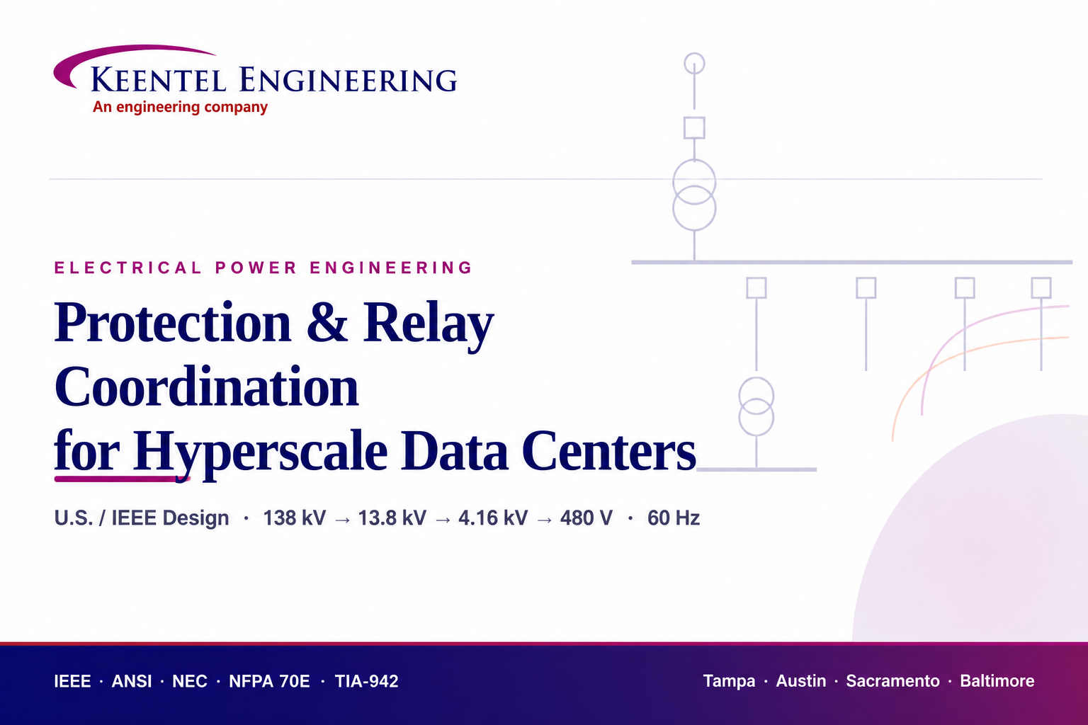
Learn electrical protection and relay coordination for hyperscale data centers with IEEE standards, short-circuit studies, arc-flash analysis, and MV protection.
By SANDIP R PATEL
•
July 18, 2026
Explore Battery Energy Storage System components, including cells, PCS, BMS, EMS, cooling, fire protection, sizing, safety, and grid codes.

By SANDIP R PATEL
•
July 18, 2026
Explore how grid-forming inverters support BESS, synthetic inertia, grid-code compliance, plant sizing, testing, and project revenue.
By SANDIP R PATEL
•
July 18, 2026
Learn how SEL RTAC protection monitoring supports NERC PRC-005 compliance, predictive maintenance alarms, automated reporting, and relay verification.

By SANDIP R PATEL
•
July 17, 2026
Explore utility-scale BESS design from the 10% package to IFC, NFPA 855 compliance, PSS®E/PSCAD models, and ERCOT interconnection.
By SANDIP R PATEL
•
July 17, 2026
Substation design guide, electrical substation design, substation equipment sizing, IEEE 80 grounding design, IEEE 998 lightning shielding, bus configuration design
By SANDIP R PATEL
•
July 15, 2026
Learn how medium-voltage switchgear improves data center reliability with expert guidance on MV architecture, protection, redundancy, commissioning, and maintenance.


