
A Coordinated Electric System Interconnection Review—the utility’s deep-dive on technical and cost impacts of your project.
Challenge: Frequent false tripping using conventional electromechanical relays
Solution: SEL-487E integration with multi-terminal differential protection and dynamic inrush restraint
Result: 90% reduction in false trips, saving over $250,000 in downtime
ERCOT enforces all of the above through simulation, which means your model is your compliance case. The bar is now high:
- Whole-facility scope. The model must represent everything the IT load, the UPS and power conversion, the cooling plant, the protection and control systems in formats compatible with ERCOT's study platforms (PSS/E, PSCAD, TSAT).
- Real control loops, not approximations. Generic textbook representations are unacceptable. The model must capture the actual inner control behavior of your power electronics.
- Hardware-validated converter models. For electronic loads, the PSCAD model must be benchmarked against actual hardware testing including voltage ride-through and subsynchronous response. A model assembled from standard PSCAD library blocks fails by definition, because a generic block has never been tested against your vendor's hardware. The good news: validation is a hardware-type test, so results for a given converter product are reusable across every facility that uses it.
- Format migration. Facilities that previously submitted the older composite load model (CMLD) format must transition to EPRI's PERC1 format.
- Three checkpoints. Models are reviewed before the stability study begins (no model, no study), before each quarterly stability assessment, and for electronic loads one final time before energization, when you must submit as-built models with a documented comparison against the previously studied data and a sworn attestation that the model matches actual field settings. ERCOT's review takes 10 business days, extendable by 20 put it on your critical path.
- A living obligation. Change your technology, controls, or relay settings in a way that affects ride-through including converting a crypto mining site to an AI data center — and you've triggered a new interconnection study, even if your megawatts don't change.
| Parameter | Detail |
|---|---|
| System | 230 kV / 138 kV transmission corridors, wind and wet-snow icing exposure |
| Data basis | 15 years of minute-resolution forced-outage records + regional weather observations |
| Core methods | Event grouping, MVA performance curves, time-to-95%-restore, area outage rate curves, fragility modeling, rerun-history benefits, exceedance and log-domain risk metrics |
| Headline result | ≈85% of maximum resilience benefit at 60% of original capital; worst-event restoration window cut from 11 days to 5 in rerun-history terms |
| Decision supported | Capital portfolio selection; resilience plan filing; post-investment verification framework |
| System / Topic | Governing Standard(s) | What It Controls |
|---|---|---|
| Overall plant electrical distribution | IEEE 141 (Red Book); IEEE 666 | Distribution architecture, voltage selection, design of generating station auxiliary service systems |
| Power system studies | IEEE 399 (Brown Book); IEEE 551 | Load flow, symmetrical/asymmetrical short circuit, motor starting methodologies down to the lowest LV panelboard |
| Protection & coordination | IEEE 242 (Buff Book); IEEE 3004.5; IEEE C37 series | Generator relaying (21, 59N, 87G), time-current coordination, selective clearing between LV and MV tiers |
| GSU / UAT / SST transformers | IEEE C57.12.00 and C57 family | Transformer ratings, impedance, testing, loading |
| HV switchyard breakers | IEEE C37.06 | AC high-voltage circuit breaker preferred ratings |
| MV switchgear (13.8 kV) | IEEE C37.20.2; IEEE C37.20.7 | Metal-clad construction, compartmentalization, vacuum breakers; arc-resistant design with plenum venting |
| MV cable | UL 1072; ICEA S-93-639 (NEMA WC 74) | Type MV-105 shielded cable, 133% insulation level for HRG systems |
| LV switchgear (480 V) | IEEE C37.13; UL 1558 | Metal-enclosed LV power circuit breaker switchgear to 635 V, draw-out ACBs with electronic trip units |
| Motor control centers | UL 845; NEMA ICS 18 | LV-MCC construction, MCCB/MCP protection for motors under ~200 HP |
| Motors | NEMA MG-1 | Motor performance, starting characteristics, service factors |
| DC & battery systems | IEEE 485; IEEE 946 | Lead-acid battery sizing (125/250 VDC), DC auxiliary system design |
| Grounding | IEEE 80; IEEE 142 (Green Book) | Ground grid step/touch potential limits; system grounding including high-resistance grounding |
| Lightning protection | IEEE 998 | Direct-stroke shielding of switchyard and outdoor generator structures |
| Arc flash & electrical safety | IEEE 1584; NFPA 70E | Incident energy calculation; worker safety boundaries and PPE |
| Fire protection | NFPA 850 | Fire protection and risk management for combustion turbine generating plants |
| Installation code | NEC (NFPA 70); NESC | Wiring methods inside the plant fence; overhead/outdoor clearances at the switchyard |
| Interconnection & compliance | FERC LGIP; NERC MOD-025/026/027, PRC-019/024/029, FAC-008 | Interconnection process, model validation, protection/ride-through coordination, facility ratings |
| IFC / Construction Deliverable | Purpose |
|---|---|
| Stamped IFC packages | Legal basis for construction; P.E. responsible charge |
| Final relay settings & TCCs | Protection as-installed matches the coordination study |
| Calculation archive | Owner records; NERC audit evidence trail |
| Commissioning procedures | Safe, sequenced energization; MOD field testing |
| Construction support | RFIs, field changes, FAT/SAT witness |
| As-builts & model handoff | Operating baseline; future study currency |
| Metric | Outcome |
|---|---|
| Defects found pre-occupancy | Three topology defects and one settings-mismatch family corrected before load migration; the shared-switchboard defect alone would have invalidated the concurrently-maintainable claim on day one |
| IST findings | Fourteen additional discrepancies surfaced under scenario testing (control logic, alarm mapping, one generator sequencing fault) — all closed before handover instead of during operations |
| Black-building test | Passed on second execution; the first attempt exposed the generator sequencing fault under true block load, exactly the failure the compressed plan would never have found |
| Handover quality | Operations team certified on the actual failure scenarios; corrected EOPs and settings documentation delivered as controlled documents |
| Business outcome | Occupancy proceeded three weeks behind the original date — against an independent estimate that the uncorrected sequencing fault carried a high probability of a full facility outage within the first year |
Part 2 — Frequently Asked Questions: Large Load Interconnection
| Contact | Details |
|---|---|
| Headquarters | 400 N Ashley Dr STE 2600, Tampa, FL 33602 |
| Phone | (813) 389-7871 |
| contact@keentelengineering.com | |
| Florida Firm Registration | No. 36853 |
| Additional Offices | Austin, TX • Sacramento, CA • Baltimore, MD |
| Who | Acronym | Plain-English Role |
|---|---|---|
| ERCOT | — | The grid's air traffic controller. It doesn't own power lines or plants; it directs the flow of electricity across most of Texas and referees the admission process for new generators. |
| Interconnecting Entity | IE | You — the developer or owner trying to connect a new plant (or significantly modify an existing one). You file the application and drive the process. |
| Resource Entity | RE | The registered owner/operator of the generator once it becomes an official market participant. Often the same company as the IE, wearing a different hat. |
| Qualified Scheduling Entity | QSE | Your plant's voice on the grid. The QSE handles round-the-clock communications with ERCOT — telemetry, schedules, dispatch instructions. Every generator must have one. |
| Transmission Service Provider | TSP | The utility that owns the wires and substation you'll connect to. The TSP runs your detailed study, builds the connection facilities, and signs your interconnection contract. |
| RIOO-IS | — | ERCOT's online portal where the whole process lives — applications, documents, status tracking, and checklists all flow through it. |
| Who | Acronym | Plain-English Role |
|---|---|---|
| ERCOT | — | The grid's air traffic controller. It doesn't own power lines or plants; it directs the flow of electricity across most of Texas and referees the admission process for new generators. |
| Interconnecting Entity | IE | You — the developer or owner trying to connect a new plant (or significantly modify an existing one). You file the application and drive the process. |
| Resource Entity | RE | The registered owner/operator of the generator once it becomes an official market participant. Often the same company as the IE, wearing a different hat. |
| Qualified Scheduling Entity | QSE | Your plant's voice on the grid. The QSE handles round-the-clock communications with ERCOT — telemetry, schedules, dispatch instructions. Every generator must have one. |
| Transmission Service Provider | TSP | The utility that owns the wires and substation you'll connect to. The TSP runs your detailed study, builds the connection facilities, and signs your interconnection contract. |
| RIOO-IS | — | ERCOT's online portal where the whole process lives — applications, documents, status tracking, and checklists all flow through it. |
| Who | Acronym | Plain-English Role |
|---|---|---|
| ERCOT | — | The grid's air traffic controller. It doesn't own power lines or plants; it directs the flow of electricity across most of Texas and referees the admission process for new generators. |
| Interconnecting Entity | IE | You — the developer or owner trying to connect a new plant (or significantly modify an existing one). You file the application and drive the process. |
| Resource Entity | RE | The registered owner/operator of the generator once it becomes an official market participant. Often the same company as the IE, wearing a different hat. |
| Qualified Scheduling Entity | QSE | Your plant's voice on the grid. The QSE handles round-the-clock communications with ERCOT — telemetry, schedules, dispatch instructions. Every generator must have one. |
| Transmission Service Provider | TSP | The utility that owns the wires and substation you'll connect to. The TSP runs your detailed study, builds the connection facilities, and signs your interconnection contract. |
| RIOO-IS | — | ERCOT's online portal where the whole process lives — applications, documents, status tracking, and checklists all flow through it. |
| Who | Acronym | Plain-English Role |
|---|---|---|
| ERCOT | — | The grid's air traffic controller. It doesn't own power lines or plants; it directs the flow of electricity across most of Texas and referees the admission process for new generators. |
| Interconnecting Entity | IE | You — the developer or owner trying to connect a new plant (or significantly modify an existing one). You file the application and drive the process. |
| Resource Entity | RE | The registered owner/operator of the generator once it becomes an official market participant. Often the same company as the IE, wearing a different hat. |
| Qualified Scheduling Entity | QSE | Your plant's voice on the grid. The QSE handles round-the-clock communications with ERCOT — telemetry, schedules, dispatch instructions. Every generator must have one. |
| Transmission Service Provider | TSP | The utility that owns the wires and substation you'll connect to. The TSP runs your detailed study, builds the connection facilities, and signs your interconnection contract. |
| RIOO-IS | — | ERCOT's online portal where the whole process lives — applications, documents, status tracking, and checklists all flow through it. |
| Who | Acronym | Plain-English Role |
|---|---|---|
| ERCOT | — | The grid's air traffic controller. It doesn't own power lines or plants; it directs the flow of electricity across most of Texas and referees the admission process for new generators. |
| Interconnecting Entity | IE | You — the developer or owner trying to connect a new plant (or significantly modify an existing one). You file the application and drive the process. |
| Resource Entity | RE | The registered owner/operator of the generator once it becomes an official market participant. Often the same company as the IE, wearing a different hat. |
| Qualified Scheduling Entity | QSE | Your plant's voice on the grid. The QSE handles round-the-clock communications with ERCOT — telemetry, schedules, dispatch instructions. Every generator must have one. |
| Transmission Service Provider | TSP | The utility that owns the wires and substation you'll connect to. The TSP runs your detailed study, builds the connection facilities, and signs your interconnection contract. |
| RIOO-IS | — | ERCOT's online portal where the whole process lives — applications, documents, status tracking, and checklists all flow through it. |
| Who | Acronym | Plain-English Role |
|---|---|---|
| ERCOT | — | The grid's air traffic controller. It doesn't own power lines or plants; it directs the flow of electricity across most of Texas and referees the admission process for new generators. |
| Interconnecting Entity | IE | You — the developer or owner trying to connect a new plant (or significantly modify an existing one). You file the application and drive the process. |
| Resource Entity | RE | The registered owner/operator of the generator once it becomes an official market participant. Often the same company as the IE, wearing a different hat. |
| Qualified Scheduling Entity | QSE | Your plant's voice on the grid. The QSE handles round-the-clock communications with ERCOT — telemetry, schedules, dispatch instructions. Every generator must have one. |
| Transmission Service Provider | TSP | The utility that owns the wires and substation you'll connect to. The TSP runs your detailed study, builds the connection facilities, and signs your interconnection contract. |
| RIOO-IS | — | ERCOT's online portal where the whole process lives — applications, documents, status tracking, and checklists all flow through it. |
| Who | Acronym | Plain-English Role |
|---|---|---|
| ERCOT | — | The grid's air traffic controller. It doesn't own power lines or plants; it directs the flow of electricity across most of Texas and referees the admission process for new generators. |
| Interconnecting Entity | IE | You — the developer or owner trying to connect a new plant (or significantly modify an existing one). You file the application and drive the process. |
| Resource Entity | RE | The registered owner/operator of the generator once it becomes an official market participant. Often the same company as the IE, wearing a different hat. |
| Qualified Scheduling Entity | QSE | Your plant's voice on the grid. The QSE handles round-the-clock communications with ERCOT — telemetry, schedules, dispatch instructions. Every generator must have one. |
| Transmission Service Provider | TSP | The utility that owns the wires and substation you'll connect to. The TSP runs your detailed study, builds the connection facilities, and signs your interconnection contract. |
| RIOO-IS | — | ERCOT's online portal where the whole process lives — applications, documents, status tracking, and checklists all flow through it. |
Protection Design
Essential Protection Settings of Air Circuit Breakers (ACBs)
Aug 8, 2026 | Blog
1. Introduction
The air circuit breaker (ACB) is the workhorse at the top of most low-voltage distribution systems — the incoming device on main switchboards, the tie between bus sections, and the feeder breaker for the largest downstream loads. Unlike a simple thermal-magnetic moulded-case breaker, a modern ACB is fitted with an electronic trip unit (also called a protection relay or release) whose behaviour is defined almost entirely by how it is set. Two identical breakers, same frame, same rating, can protect a system beautifully or trip a plant offline at every motor start — the difference is the settings.
This is why protection engineers treat ACB configuration as a discipline in its own right. The settings determine how much current the breaker allows before it acts, how long it waits, and how it coordinates with the devices above and below it so that a fault is cleared by the nearest breaker only, leaving the rest of the system energized. Get it right and you have selective, reliable protection that safeguards cables, busbars and equipment. Get it wrong and you have either nuisance tripping that erodes availability, or sluggish protection that lets fault energy damage the very assets it is meant to protect.
This article, prepared by the engineering team at Keentel Engineering, explains the essential ACB protection settings — the widely used LSIG model of Long-time, Short-time, Instantaneous and Ground-fault protection, plus neutral protection — what each parameter does, how the parameters interact, and how they are coordinated and commissioned in practice. It is written for protection, electrical and commissioning engineers. A detailed FAQ and three fully anonymized case studies follow the main text.
2. First, Get the Reference Right: In versus Ir
Every ACB setting is expressed as a multiple of a base current, so the first thing to be clear about is which base. In is the rated (sensor) current of the trip unit — the reference the manufacturer builds the device around. Ir (sometimes written I1) is the long-time pickup, the actual overload threshold the engineer sets, expressed as a fraction of In (for example Ir = 0.8 × In). Downstream settings such as short-time and instantaneous pickup are then usually expressed as multiples of Ir, while ground-fault pickup is generally a fraction of In. Confusing In with Ir is one of the most common — and most consequential — setting errors, because it shifts the entire protection curve.
3. The LSIG Protection Model at a Glance
Modern ACB trip units implement up to four current-based protection functions, remembered by the acronym LSIG. Each function is a “band” on the time–current curve, and each is defined by a pickup (how much current) and, except for instantaneous, a delay (how long). A separate neutral-protection setting extends overload/fault protection to the neutral conductor in three-phase four-wire systems.
| Function | Symbol | What it protects against | Typical setting range |
|---|---|---|---|
| Long-time pickup | Ir | Sustained overload — the maximum continuous current the circuit may carry before tripping. | 0.4–1.0 × In |
| Long-time delay | Tr | How long a passing overload is tolerated before trip (inverse, I²t). | ~ up to 30 s (at 6×Ir) |
| Short-time pickup | Isd | Higher overcurrents — motor starting inrush, transformer inrush, through-faults. | 1.5–10 × Ir |
| Short-time delay | Tsd | Intentional delay for selectivity with downstream devices (I²t ON/OFF). | ~0.1–0.6 s |
| Instantaneous pickup | Ii | Very high-magnitude faults — trips with no intentional delay. | 2–15 × In (or OFF) |
| Ground-fault pickup | Ig | Earth (residual) faults — detects unbalanced current returning via earth. | 0.2–1.0 × In |
| Ground-fault delay | Tg | Delay to ride through transient imbalance and coordinate earth-fault trips. | ~0.1–0.6 s |
| Neutral protection | N | Overload/fault protection of the neutral conductor (harmonic/unbalanced loads). | OFF / 50% / 100% |
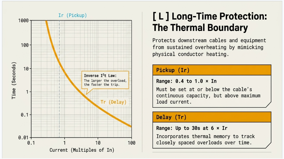
4. Long-Time Protection (Ir + Tr): The Overload Band
Long-time protection is the ACB’s thermal-overload function. The pickup Ir defines the boundary between “normal” and “overload”; below Ir the breaker carries current indefinitely, above it the breaker will eventually trip. Ir is set to protect the downstream cable and equipment, so it is chosen at or below the continuous current-carrying capacity of the circuit — never above it — while sitting comfortably above the expected maximum load current.
The long-time delay Tr sets how long an overload is tolerated before tripping, and the characteristic is inverse: the larger the overload, the shorter the time to trip, following an I²t (constant thermal-energy) law that mimics the heating of a conductor. Tr is therefore usually quoted at a reference multiple such as 6 × Ir. A longer Tr lets brief, benign overloads — a cluster of motors starting, a transformer energizing — pass without tripping; a shorter Tr protects thermally sensitive cable more aggressively. Many trip units also provide thermal memory, so repeated or closely spaced overloads accumulate rather than resetting the timer each time, reflecting the real thermal state of the conductor.
5. Short-Time Protection (Isd + Tsd): Riding Through and Discriminating
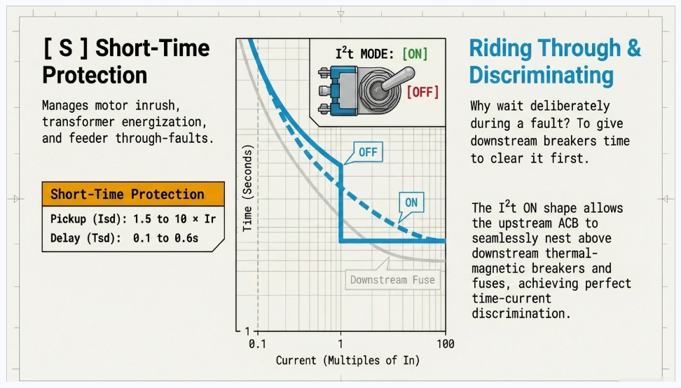
Between ordinary overload and a bolted short circuit lies a band of higher overcurrents — motor and transformer inrush, feeder through-faults — where the engineer wants control over both threshold and timing. That is the short-time band. The pickup Isd (a multiple of Ir) sets where short-time protection begins; the delay Tsd introduces an intentional, deliberate wait.
Why wait deliberately during a fault? Because of selectivity. If a fault occurs on a downstream feeder, the downstream breaker should clear it while the upstream ACB holds in, so that only the faulted circuit is lost. A short-time delay on the upstream device gives the downstream device time to operate first — the essence of time-current discrimination. The trade-off is that any delay lets more energy through, so Tsd is kept as short as coordination allows, and it must remain within the breaker’s short-time withstand rating (Icw).
Most trip units offer an
I²t ON / I²t OFF
choice for the short-time region. With I²t OFF, the delay is a fixed (definite) time above Isd. With I²t ON, the delay follows an inverse ramp at lower currents before flattening — this shapes the curve to nest neatly above downstream fuses and thermal-magnetic breakers, improving discrimination with I²t-limited devices. Selecting the right mode is often the key to clean coordination.
6. Instantaneous Protection (Ii): No Deliberate Delay
The instantaneous function trips the breaker with no intentional time delay once current exceeds the pickup Ii, giving the fastest possible clearance for very high-magnitude faults close to the breaker. Because it has no delay,
instantaneous protection cannot discriminate with downstream devices — so on an upstream ACB where full selectivity is required, Ii is often raised high or switched OFF (subject to the breaker’s withstand rating and to any short-circuit protection provided by short-time). On the lowest-level device, by contrast, a low instantaneous setting clears faults quickly and limits let-through energy. The correct choice depends entirely on where the breaker sits in the coordination scheme.
7. Ground-Fault Protection (Ig + Tg): Catching Earth Faults Early
Earth faults often start small — a degraded insulation path, a loose termination — and draw current that returns through the earth/ground rather than the phase or neutral conductors. Such currents can be far below the phase-overcurrent pickups, so a dedicated ground-fault function is needed to detect them before they escalate into fire or equipment damage. The trip unit computes the residual (vector sum) of the phase currents (and neutral, where measured); a non-zero residual indicates current leaking to earth.
Ground-fault pickup Ig is set as a fraction of In, low enough to catch developing faults but above normal standing leakage and expected imbalance. The delay Tg lets the function ride through brief transient imbalances (for example during switching) and, importantly, allows earth-fault selectivity so a downstream earth fault is cleared downstream. Ig and Tg together protect people and plant from the insidious, low-level faults that phase protection can miss.
8. Neutral Protection (N): Not an Afterthought
In three-phase four-wire systems the neutral can carry significant current — from single-phase load imbalance and, increasingly, from triplen (3rd, 9th…) harmonics produced by electronic loads, which add arithmetically in the neutral rather than cancelling. An undersized or unprotected neutral can overheat even when the phases look healthy. Neutral protection extends the ACB’s overload/short-time logic to the neutral pole, typically selectable as OFF, 50% or 100% of the phase setting.
Where the neutral is full-sized and harmonic content is high, 100% neutral protection is common; a half-rated setting suits reduced-neutral installations.Choosing this correctly prevents a hidden thermal risk from going unprotected.
9. Worked Interpretation of a Typical Trip-Unit Readout
It helps to read a real settings string the way the breaker does. Taking a representative electronic trip-unit display of the kind shown on ACB relay units, the values translate as follows (In being the trip-unit rated current):
| Displayed | Setting | Engineering meaning |
|---|---|---|
| Ir = 0.80 × In | Long-time pickup | Overload threshold at 80% of rated current — matched to the protected cable’s capacity. |
| Tr = 30 s | Long-time delay | Tolerates a 6×Ir overload for up to ~30 s (inverse I²t), riding through benign transients. |
| Isd = 6.0 × In | Short-time pickup | Short-time protection engages at six times the reference current (through-faults / inrush). |
| (Tsd ≈ 0.3 s) | Short-time delay | Holds ~0.3 s to let a downstream device clear first — provides time discrimination. |
| Ii = 10 × In | Instantaneous | Trips with no delay above ten times rated current for severe close-up faults. |
| Ig = 0.40 × In | Ground-fault pickup | Detects earth (residual) fault current at 40% of rated current. |
| Tg = 0.30 s | Ground-fault delay | Rides through transient imbalance and coordinates earth-fault clearing. |
Read together, this string describes a selective incomer: a realistic overload threshold, delays on short-time and ground-fault to let downstream devices act first, and a high instantaneous pickup so the ACB only trips instantly for the most severe faults. Every value has a reason, and every value must be justified against the cable data, the load profile and the coordination study.
10. Coordination and Selectivity: The Whole Point
Individual settings matter, but the objective is system behaviour: when a fault occurs, only the breaker nearest the fault should operate. This is selectivity (discrimination), achieved by separating the time–current curves of series devices so they never overlap in a way that trips the wrong breaker. Engineers use several, often combined, methods.
| Method | How it achieves selectivity |
|---|---|
| Current discrimination | Upstream pickups (Ir, Isd) set higher than downstream, so lower-level faults are seen only downstream. Simple, but limited where fault levels are similar up and down the chain. |
| Time discrimination | Upstream delays (Tr, Tsd, Tg) set longer than downstream by a coordination margin, so the downstream device always operates first. Must stay within the breaker’s Icw withstand. |
| Energy / I²t discrimination | Uses I²t curve-shaping and current-limiting behaviour so the downstream device lets through less energy than the upstream device needs to trip. Extends selectivity to high fault levels. |
| Zone-selective interlocking (ZSI) | Breakers communicate over a wiring link: a downstream device detecting a fault signals the upstream device to hold its short-time/ground-fault delay, but if no downstream device reports the fault, the upstream device trips fast. Delivers fast clearing AND selectivity together. |
The upshot is that ACB settings can never be chosen device-by-device in isolation. They emerge from a protection coordination (discrimination) study that plots every series device on a single time–current chart, checks fault levels at each point, and verifies that the curves are properly nested from the load right up to the source.
11. Commissioning and Good-Practice Setting Rules
A setting is only as good as its verification. Sound practice, echoing the guidance summarized on the source infographic, comes down to a short discipline:
- Coordinate every setting with upstream and downstream devices — never set a breaker in isolation; work from a discrimination study.
- Stay within the manufacturer’s recommended ranges and the device’s ratings (In, Icw, Icu) — settings outside the intended envelope are unreliable or unsafe.
- Match Ir to the protected cable and Ig/N to the earthing and neutral arrangement — protect the conductor, not just the load.
- Test every protection function after adjustment — primary or secondary injection to confirm pickups and delays behave as set.
- Document the as-left settings, and review and update them whenever loads, generation, or the network topology change.
12. Why It Matters — and Where Keentel Helps
Correctly configured ACB protection delivers four things at once: reliable protection through accurate, selective tripping; system stability by avoiding unnecessary trips of healthy circuits; easy, repeatable commissioning; and equipment safety that extends asset life. These are not competing goals — a good coordination study achieves them together. The reverse is equally true: a single mis-set delay or a confused In/Ir reference can either black out a facility on a routine motor start or let a downstream fault damage a main switchboard.
This is precisely the work Keentel Engineering supports — protection coordination and discrimination studies, trip-unit setting calculations, ZSI and selectivity design, and commissioning and injection-test support — so that every ACB in a distribution system is set with intent, verified by test, and documented for the life of the installation.
Confidential Case Studies
The following three case studies are fully anonymized. They contain no client names, project names, locations or other identifying details, and describe generalized scenarios composited from typical protection-engineering assignments to illustrate how ACB setting decisions are made in practice.
Case Study 1 — Eliminating Nuisance Tripping on Motor Inrush
| Setting | Industrial facility with large motor loads (confidential) |
|---|---|
| Challenge | An incoming ACB tripped intermittently during motor starting |
| Focus | Short-time pickup/delay (Isd, Tsd) and I²t shaping |
Situation
A distribution board feeding several large induction motors experienced repeated, seemingly random trips of the section’s air circuit breaker, always during periods of high starting activity. Production was interrupted with no fault ever found on inspection — the classic signature of protection that is mis-set rather than a genuine fault.
Investigation
A review of the trip-unit settings and the motor data showed the short-time pickup (Isd) had been left low and the short-time delay (Tsd) short, so the combined inrush of simultaneous direct-on-line starts — several times full-load current for a few hundred milliseconds — was crossing into the short-time trip region. The instantaneous setting was also low enough to be grazed by inrush peaks. Nothing was faulty; the curve simply did not accommodate legitimate starting current.
Resolution
The engineering team recalculated the short-time band to sit above the aggregate starting inrush with margin, adjusted the short-time delay to ride through the starting period while remaining within the breaker’s short-time withstand, selected the appropriate I²t mode to preserve coordination with downstream motor protection, and raised the instantaneous pickup so it responded only to genuine short-circuit magnitudes. Long-time pickup was confirmed against the feeder cable rating so overload protection was retained.
Outcome
- Nuisance trips during motor starting were eliminated, restoring uninterrupted operation.
- Genuine overload and short-circuit protection remained fully intact and within device ratings.
- Downstream coordination was preserved, so a real motor-circuit fault would still be cleared locally.
- The corrected settings were documented and injection-tested to confirm behaviour.
Case Study 2 — Restoring Selectivity Between an Incomer and a Feeder
| Setting | Commercial/critical facility switchboard (confidential) |
|---|---|
| Challenge | A downstream feeder fault tripped the main incomer, blacking out the board |
| Focus | Time/energy discrimination and zone-selective interlocking |
Situation
On a switchboard supplying a facility that could not tolerate loss of the whole board, a fault on one downstream feeder tripped not only that feeder’s breaker but also the main incoming ACB, de-energizing every circuit on the board. A local fault had become a total outage — a selectivity failure.
Investigation
Plotting the incomer and feeder time–current curves on a single chart revealed overlap in the short-time region: the incomer’s short-time delay was not long enough above the feeder’s clearing time to guarantee the feeder tripped first, and at the prevailing fault level the two curves crossed. In effect both devices “saw” the fault as instantaneous and raced, with the incomer sometimes winning.
Resolution
The team re-graded the short-time settings to open a proper coordination margin between feeder and incomer, applied I²t curve-shaping to maintain discrimination up to the board’s fault level, and — because simply lengthening the incomer’s delay would have raised let-through energy — implemented zone-selective interlocking so the feeder could signal the incomer to hold, while preserving fast incomer tripping for a fault on the bus itself. Instantaneous on the incomer was coordinated accordingly.
Outcome
A downstream feeder fault is now cleared by the feeder breaker alone; the rest of the board stays energized.
The incomer still trips quickly for a genuine busbar fault, so protection speed was not sacrificed.
Let-through energy at the incomer was kept low through ZSI rather than long fixed delays.
The coordination study and as-left settings were documented for future changes.
Case Study 3 — Catching a Hidden Earth Fault and Neutral Overheating
| Setting | Three-phase four-wire installation with electronic loads (confidential) |
|---|---|
| Challenge | Overheating and a developing earth fault not seen by phase protection |
| Focus | Ground-fault pickup/delay (Ig, Tg) and neutral protection (N) |
Situation
An installation with a high proportion of non-linear electronic loads showed signs of thermal distress — elevated temperatures at the switchboard neutral and intermittent tripping — while the phase currents appeared within limits. Phase-overcurrent protection alone was not telling the whole story.
Investigation
Two issues surfaced. First, triplen harmonics from the electronic loads were adding in the neutral conductor, driving neutral current well above expectations while phase readings looked normal, and the neutral protection had been left disabled. Second, a low-level earth fault was drawing residual current below the phase pickups, so the phase functions never reacted; the ground-fault settings were too insensitive and slow to catch it early.
Resolution
The team enabled and set neutral protection appropriate to the (full-sized) neutral and the harmonic loading so the neutral pole was protected against the elevated current, and recalculated the ground-fault pickup (Ig) to a sensitivity that would catch a developing earth fault while staying above normal standing leakage and imbalance, with a ground-fault delay (Tg) chosen to ride through switching transients and coordinate with downstream earth-fault clearing.
Outcome
- The developing earth fault was detected and cleared early, before it could escalate to equipment damage or fire.
- Neutral protection now guards against harmonic-driven neutral overheating that phase protection cannot see.
- Ground-fault and neutral settings were coordinated with downstream devices to avoid nuisance tripping.
- All changes were injection-tested and documented, with a recommendation to re-review as harmonic loads grow.
Work With Keentel Engineering
Whether the issue is nuisance tripping on starting loads, a selectivity failure that turns a local fault into an outage, or hidden earth-fault and neutral risks in a harmonic-rich installation, the answer usually lies in a rigorous
protection coordination study and disciplined, tested trip-unit settings. Keentel Engineering supports facility owners, contractors and utilities with discrimination studies, ACB and trip-unit setting calculations, ZSI and selectivity design, and commissioning and injection-test support. Talk to our protection team about your switchboard.
Frequently Asked Questions
Detailed answers to the questions engineers most often ask about ACB protection settings.
Q1. What does LSIG stand for?
LSIG is the standard shorthand for the four current-based protection functions in a modern ACB electronic trip unit: L for Long-time (overload), S for Short-time (delayed overcurrent for selectivity), I for Instantaneous (undelayed, high-magnitude faults), and G for Ground-fault (earth/residual faults). A trip unit may be LSI (no ground fault) or LSIG. Neutral protection is an additional setting layered on top.
Q2. What is the difference between In and Ir?
In is the rated (sensor) current of the trip unit — the fixed reference the device is built around. Ir is the long-time pickup you set, expressed as a fraction of In (e.g. 0.8 × In), and it defines the actual overload threshold. Short-time and instantaneous pickups are usually multiples of Ir, while ground-fault pickup is a fraction of In. Mixing up In and Ir shifts the whole protection curve, so always confirm which base a given multiple refers to.
Q3. How do I choose the long-time pickup (Ir)?
Set Ir to protect the downstream cable and equipment: at or below the continuous current-carrying capacity of the circuit (after derating), and comfortably above the maximum expected load current so normal operation never trips it. In effect Ir is squeezed between “must be below cable rating” and “must be above real load” — if there is no gap, the cable or the load plan needs revisiting, not the setting.
Q4. What is the long-time delay (Tr) and why is it inverse?
Tr sets how long an overload is tolerated before tripping. The characteristic is inverse (I²t): the bigger the overload, the faster the trip, mirroring how a conductor heats. This lets brief, benign overloads — motor starts, transformer inrush — pass, while sustained overloads trip in time to protect the cable. Tr is usually quoted at a reference like 6 × Ir. Many trip units add thermal memory so repeated overloads accumulate rather than resetting.
Q5. Why would I deliberately delay tripping with a short-time delay (Tsd)?
For selectivity. A short-time delay on an upstream breaker gives a downstream device time to clear a downstream fault first, so only the faulted circuit is lost instead of the whole board. The delay is kept as short as coordination allows because any delay increases let-through energy, and it must stay within the breaker’s short-time withstand rating (Icw).
Q6. What does the I²t ON/OFF option on short-time do?
It changes the shape of the short-time curve. With I²t OFF, the short-time delay is a fixed (definite) time above the Isd pickup. With I²t ON, the delay follows an inverse ramp at lower currents before flattening, which helps the ACB curve sit cleanly above downstream fuses and thermal-magnetic breakers that are themselves I²t-limited — improving discrimination. The right choice depends on what is downstream.
Q7. When should instantaneous protection (Ii) be turned off or set high?
On upstream devices where full selectivity is needed. Instantaneous has no intentional delay, so it cannot discriminate with downstream breakers; if it picks up on a downstream fault, it trips the upstream device unnecessarily. Raising Ii high or switching it OFF (where the breaker’s withstand rating and short-time protection allow) preserves selectivity. On the lowest device in the chain, a low instantaneous setting is desirable for fast clearing.
Q8. How is ground-fault protection different from an RCD?
Both respond to residual (earth) current, but they operate at very different sensitivities and purposes. An RCD/RCM protects people against electric shock and trips at milliamp levels (e.g. 30 mA). ACB ground-fault protection (Ig) is equipment/earth-fault protection set as a fraction of In — typically tens of percent of hundreds or thousands of amps — to catch damaging earth faults and limit fire and equipment risk, not to provide personal shock protection.
Q9. Why does the neutral need its own protection setting?
In three-phase four-wire systems the neutral carries imbalance current and, importantly, triplen harmonics (3rd, 9th…) from electronic loads, which add up in the neutral instead of cancelling. The neutral can therefore run hot even when the phases look fine. Neutral protection (typically OFF / 50% / 100% of the phase setting) extends overload and short-time protection to the neutral pole so this hidden thermal risk is covered — 100% is common where the neutral is full-sized and harmonics are high.
Q10. What is zone-selective interlocking (ZSI) and when is it worth it?
ZSI is a communication link between breakers that gives you fast clearing and selectivity at the same time. A downstream breaker that detects a fault signals the upstream breaker to hold its short-time/ground-fault delay; if no downstream breaker reports the fault, the upstream breaker trips without waiting. This avoids the usual compromise where added delays for selectivity increase fault energy at the incomer. It is especially valuable on critical and high-fault-level switchboards.
Q11. What standard governs ACBs and their protection?
Low-voltage circuit breakers, including ACBs, are covered by IEC 60947-2 (with national equivalents). It defines ratings and terminology such as Icu (ultimate breaking capacity), Ics (service breaking capacity) and Icw (short-time withstand current), and the tests that back them. Protection settings must always be chosen within the device’s rated envelope; the trip-unit ranges themselves are defined by the manufacturer within that framework.
Q12. How often should ACB settings be reviewed?
Whenever the system that surrounds them changes — added or upsized loads, new generation (including standby generators or renewables that alter fault levels), reconfigured busbars, or replaced downstream devices — and periodically as part of planned maintenance. Settings that were selective when commissioned can lose coordination as fault levels and load profiles evolve, so a discrimination study should be revisited, and functions re-tested by injection, after significant changes.

About the Author:
Sandip "Sonny" R. Patel, P.E.
IEEE Senior Member · Founder & CEO, Keentel Engineering
In 1995, Sonny Patel earned his Electrical Engineering degree from the University of Illinois. But degrees don't build legacies — action does.
For three decades, he has worked the power industry from every side of the table: 16 years as a utility engineer at Exelon/Commonwealth Edison; generation leadership across hydroelectric, industrial steam turbine, and a 9 GW renewable fleet; NERC Regional Entity Senior Compliance Engineer and Audit Team Lead, auditing some of the nation's largest utilities; and testing and commissioning lead on equipment up to 765 kV — the very top of the North American grid.Utility. Generator. Regulator. Consultant. Few engineers have seen all four seats. Fewer still have sat in them.
His experience spans nuclear, hydro, conventional generation, renewables, oil and gas, mining — and today's data centers, where he is authoring a three-book series on data center design. He is a Licensed Professional Engineer in six states and a Licensed Electrical Contractor in Florida (Unlimited EC) — he doesn't just design the work; he's qualified to stand behind its execution.Today, as Founder and CEO of Keentel Engineering, Sonny leads a nationwide team of engineers delivering substation design, power system studies, NERC compliance, and commissioning — done right, coast to coast.Three decades. Every side of the table. One standard: accountable engineering.
Services

Let's Discuss Your Project
Let's book a call to discuss your electrical engineering project that we can help you with.
About the Author:
Sandip "Sonny" R. Patel, P.E.
IEEE Senior Member · Founder & CEO, Keentel Engineering
In 1995, Sonny Patel earned his Electrical Engineering degree from the University of Illinois. But degrees don't build legacies — action does.
For three decades, he has worked the power industry from every side of the table: 16 years as a utility engineer at Exelon/Commonwealth Edison; generation leadership across hydroelectric, industrial steam turbine, and a 9 GW renewable fleet; NERC Regional Entity Senior Compliance Engineer and Audit Team Lead, auditing some of the nation's largest utilities; and testing and commissioning lead on equipment up to 765 kV — the very top of the North American grid.
Utility. Generator. Regulator. Consultant. Few engineers have seen all four seats. Fewer still have sat in them.
His experience spans nuclear, hydro, conventional generation, renewables, oil and gas, mining — and today's data centers, where he is authoring a three-book series on data center design. He is a Licensed Professional Engineer in six states and a Licensed Electrical Contractor in Florida (Unlimited EC) — he doesn't just design the work; he's qualified to stand behind its execution.
Today, as Founder and CEO of Keentel Engineering, Sonny leads a nationwide team of engineers delivering substation design, power system studies, NERC compliance, and commissioning — done right, coast to coast.Three decades. Every side of the table. One standard: accountable engineering.
Leave a Comment
Thank you for contacting us.
We will get back to you as soon as possible.
We will get back to you as soon as possible.
Oops, there was an error sending your message.
Please try again later.
Please try again later.
Related Posts

By SANDIP R PATEL
•
September 24, 2026
Learn why continuing technical training matters in power engineering, including standards, software skills, PDH requirements, and career growth.
By SANDIP R PATEL
•
September 22, 2026
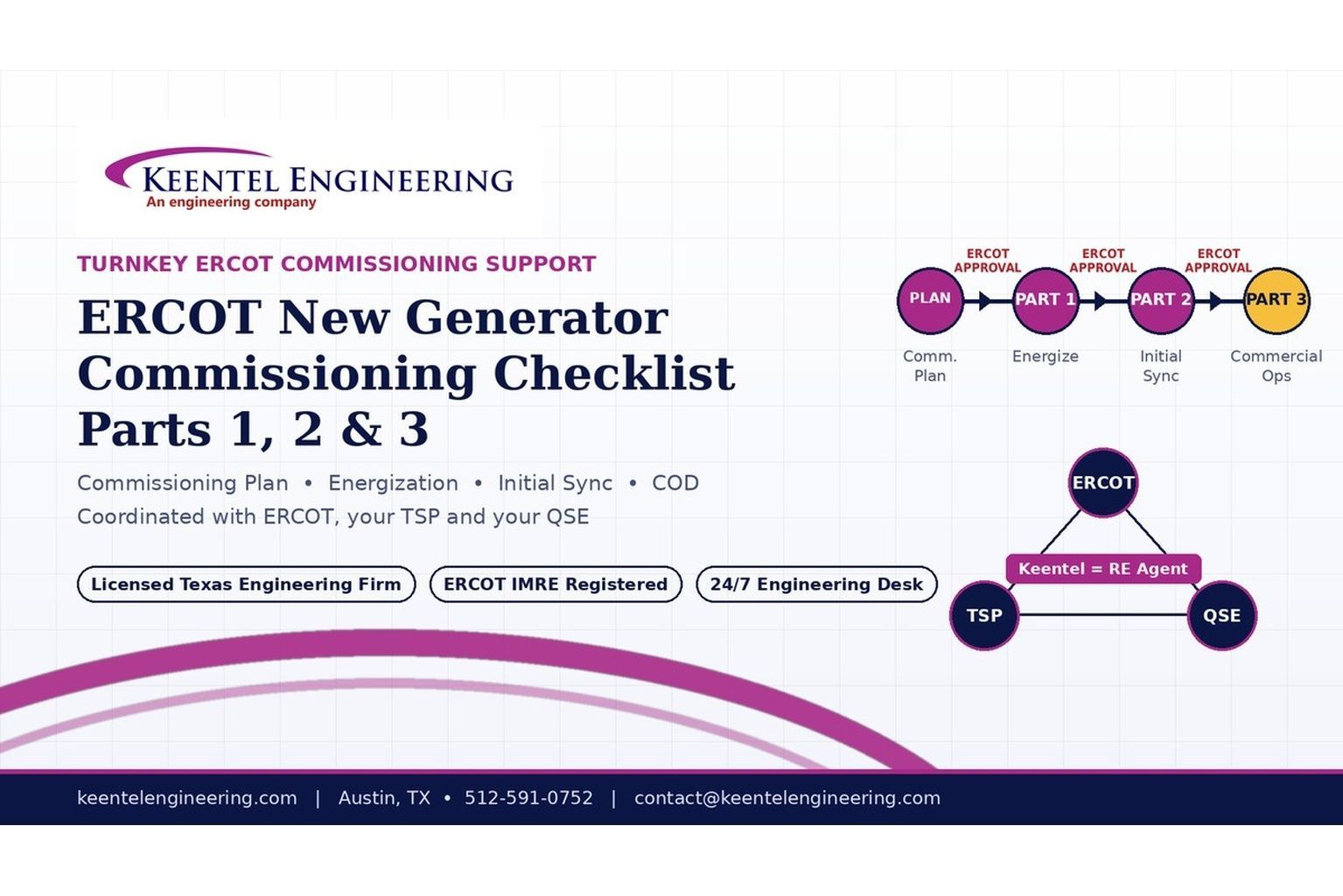
2026 ERCOT commissioning guide covering the Commissioning Plan, Checklist Parts 1–3, BESS requirements, TSP/QSE coordination, field testing and COD.

By SANDIP R PATEL
•
September 22, 2026
Learn PRC-030-1 R1 event detection requirements for inverter-based resources, SEL platforms, disturbance monitoring, and audit-ready compliance.
By SANDIP R PATEL
•
September 22, 2026
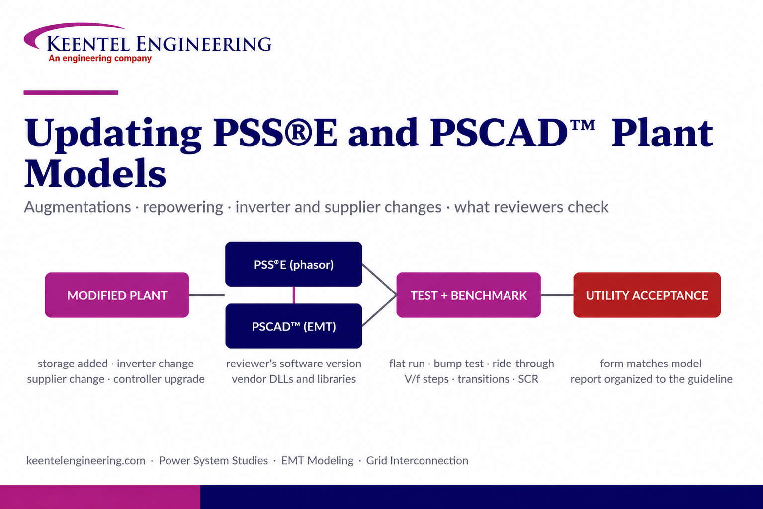
Learn how PSS®E and PSCAD™ model updates support plant augmentations, repowering, equipment changes, testing, benchmarking, and grid compliance.
By SANDIP R PATEL
•
September 20, 2026
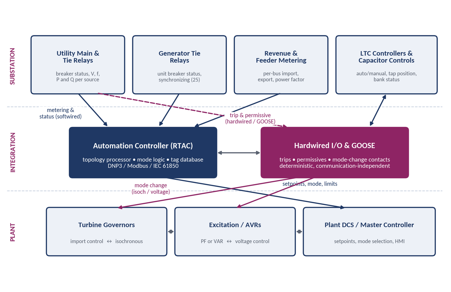
Learn CHP load following and island detection engineering for campus plants, including protection, controls, power studies, and grid transition design.
By SANDIP R PATEL
•
September 20, 2026
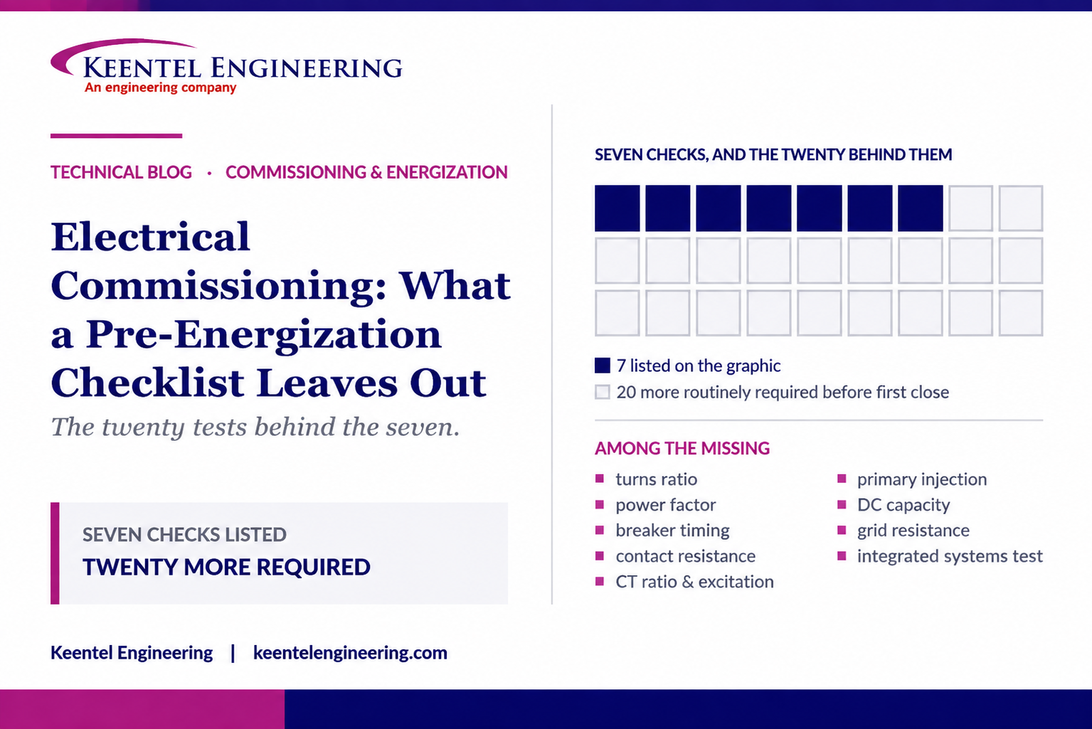
Learn what a pre-energization checklist misses, including electrical testing, protection checks, commissioning steps, and safe energization practices.
By SANDIP R PATEL
•
September 20, 2026
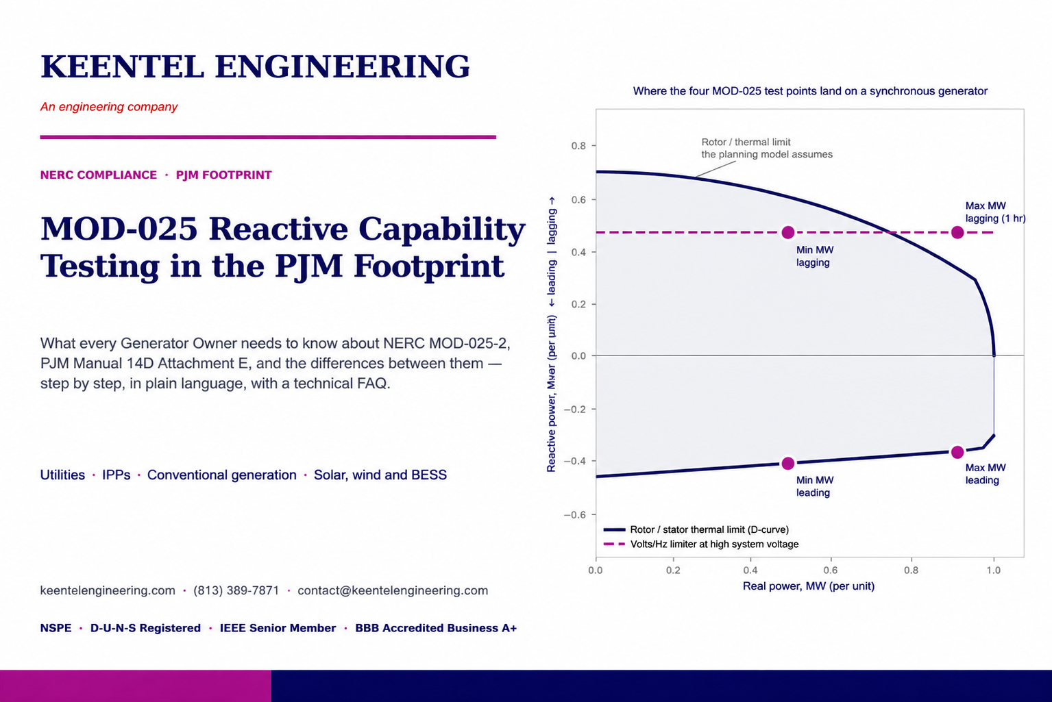
NERC MOD-025-2 Generator Owners, MOD-025-2 reactive power testing, generator capability verification, NERC Attachment 1, MOD-025 compliance testing
By SANDIP R PATEL
•
September 20, 2026
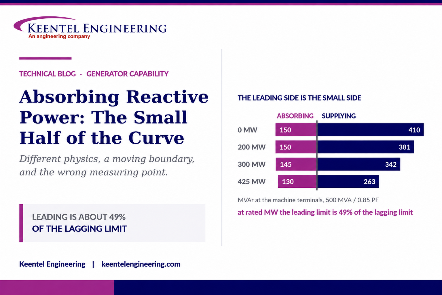
Understand generator capability curves, reactive power absorption, MVAr limits, MOD-025 verification, protection coordination, and grid requirements.
By SANDIP R PATEL
•
September 20, 2026
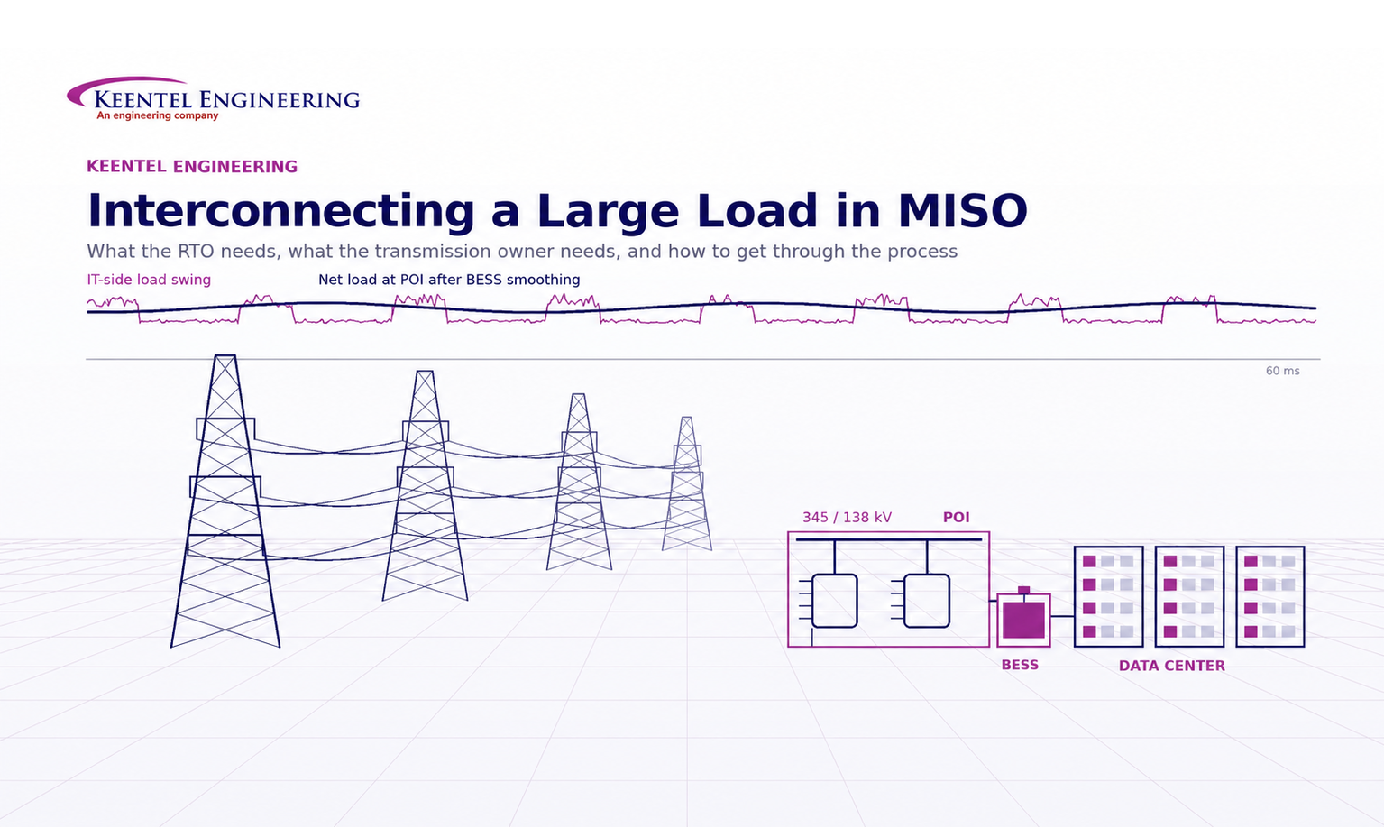
Understand MISO large load interconnection requirements for data centers, including TO data, PSS®E models, ride-through, harmonics, BESS and EPR.





