
A Coordinated Electric System Interconnection Review—the utility’s deep-dive on technical and cost impacts of your project.
Challenge: Frequent false tripping using conventional electromechanical relays
Solution: SEL-487E integration with multi-terminal differential protection and dynamic inrush restraint
Result: 90% reduction in false trips, saving over $250,000 in downtime
Advanced Protection System Modeling and Relay Coordination Using ASPEN OneLiner V15 | Technical White Paper

May 3, 2026 | Blog
1. Executive Summary
Modern protection engineering is no longer limited to calculating fault current and plotting relay curves. Transmission owners, generator owners, renewable developers, utilities, and consulting engineers now require a complete protection modeling environment that can represent:
- Network topology
- Short-circuit behavior
- Relay pickup and trip timing
- Directional supervision
- Distance relay zones
- Overcurrent phase and ground elements
- Voltage relays
- Line differential protection
- Reclosers and fuses
- Breaker interrupting capability
- Logic equations
- Communication-assisted protection schemes
- Relay database synchronization
- Automated modeling from relay setting files
ASPEN OneLiner V15 provides this type of environment. Based on the material reviewed, OneLiner V15 is not merely a short-circuit program. It is a protection system modeling and validation platform that combines power system fault simulation, relay coordination, relay database integration, API-driven automation, and logic scheme simulation.
For Keentel Engineering, this creates a strong technical foundation for services such as:
- Transmission protection coordination studies
- NERC PRC-027 coordination reviews
- Relay setting validation
- Relay model conversion and automation
- Breaker duty studies
- Renewable interconnection protection studies
- Distribution recloser-fuse coordination
- Protection logic simulation for POTT, PUTT, DUTT, DCB, and hybrid schemes
The most important value of OneLiner V15 is that it allows an engineer to model not just “a relay,” but the complete protection behavior of a system: current transformers, potential transformers, relay elements, pickup thresholds, trip delays, signal-only elements, communication delay, dropout timing, reclosing states, and terminal-open logic.
2. Why Protection Modeling Has Become More Complex
Power system protection studies have historically depended on three separate engineering tasks:
- Build or update a short-circuit model.
- Enter relay settings into a coordination program.
- Manually evaluate whether devices operate selectively and securely.
This workflow becomes difficult when applied across a large utility or generation fleet because relay settings may be stored in a separate database, relay files may be maintained by different departments, and system models may not always reflect the latest protection configuration.
The first PDF you provided explains this challenge very clearly. OneLiner has long had the ability to simulate relay response to faults, but large-scale protection representation was historically difficult because engineers had to obtain the correct relay setting file, understand which elements were actually tripping, and correctly model those functions in OneLiner. A reverse Zone 3 element used for DCB blocking, for example, should not be modeled as a tripping element. If it is modeled incorrectly, the protection study result can be misleading.
That single point is critical. A relay element can exist in the setting file but may not directly trip a breaker. It may only supervise, block, permit, alarm, or participate in a scheme. Therefore, high-quality protection modeling must distinguish between:
- Element pickup
- Element trip
- Signal-only logic
- Scheme-level trip
- Communication-assisted permission or blocking
- Actual breaker operation
This is why OneLiner V15’s API and logic modeling capabilities are so important.
3. ASPEN OneLiner V15 as a Protection Engineering Platform
ASPEN OneLiner is described as a Windows-based short-circuit and relay coordination program for relay engineers. Its purpose is productivity: it allows engineers to change relay settings or network configuration and immediately observe the impact on short-circuit results, relay operating time, curves, and diagrams.
The platform supports accurate modeling of:
- Two-winding transformers
- Three-winding transformers
- Phase shifters
- Transmission lines
- Switches
- Series capacitors with and without MOV elements
- Series reactors
- DC lines and converter terminals
- Synchronous generators
- Type-3 wind plants
- Converter-interfaced resources
- Loads
- Shunts
- Zero-sequence mutual coupling
From a protection engineering perspective, this matters because fault current magnitude, sequence quantities, voltage depression, directionality, and relay response are all dependent on the correctness of the network model. Poor transformer grounding data, incorrect zero-sequence mutual coupling, wrong CT location, or improper converter representation can change the study conclusion.
4. Fault Simulation Capabilities
Our case studies states that OneLiner supports modeling major network components and can simulate the four classical fault types, close-in faults, line-end faults, and multiple simultaneous short circuits. It can also compute pre-fault voltage from flat voltage, DC load flow, or AC load flow.
This is important because protection coordination studies often require evaluating multiple fault locations and system conditions, including:
- Three-phase bolted faults
- Single-line-to-ground faults
- Line-to-line faults
- Double-line-to-ground faults
- Close-in breaker-terminal faults
- Remote-end line faults
- Intermediate line faults
- Faults with one terminal open
- Simultaneous faults
- Branch outage conditions
OneLiner displays post-fault currents and voltages instantly on the one-line diagram. It also provides phasor probe capability so the engineer can view voltage and current vectors at any network component. Relay operating time can be shown directly at the relay location, and detailed results include branch flow, fault MVA, Thevenin impedance, and X/R ratio.
For Keentel Engineering, this supports several deliverables:
- Short-circuit study
- Relay coordination reports
- Breaker duty studies
- Relay test file exports
- Fault current validation for interconnection studies
- Protection misoperation review
Fault results can be exported in COMTRADE, Doble, CSV, and tab-delimited formats, which is valuable for relay testing, end-to-end testing, and protection system commissioning.
5. Main Window and Engineering Workflow
The Main Window section you provided shows that OneLiner is designed around a graphical one-line diagram. When a binary data file is opened, the one-line appears in the main window, and the status bar displays system base MVA, frequency, object descriptions, fault descriptions, solution status, and power-flow losses.
One of the most useful engineering features is the ability to split the main window into two panes. Each pane can show different quantities. For example, one pane may show system impedance while another shows short-circuit solution results. Each pane has independent scrolling and zoom control.
This is not just a user-interface convenience. It directly improves study quality because the engineer can compare:
- Pre-fault topology versus post-fault result
- Positive-sequence versus zero-sequence quantities
- Relay operating time versus current distribution
- One terminal versus the opposite terminal
- Before/after network modification
The toolbar supports common study actions, including specifying classical faults, specifying simultaneous faults, showing solutions on the one-line, displaying zero-, positive-, and negative-sequence quantities, displaying phase A/B/C quantities, displaying relay operating times, navigating fault solutions, running scripts, opening the TTY window, and opening relay curve windows.
This makes OneLiner useful not only for final reports but also for interactive engineering investigation.
6. Device Palette and Model Construction
The Device Palette supports drag-and-drop creation of one-line diagram objects. The engineer can add buses, generators, shunts, switched shunts, loads, annotations, lines, two-winding transformers, three-winding transformers, phase shifters, series capacitors/reactors, switches, and DC lines.
For single-terminal devices, the user selects the object and clicks on the diagram. For two-terminal devices, the user clicks and drags to define the terminals. If nearby buses exist, the program attaches to them; otherwise, it creates new buses automatically. For three-winding transformers, OneLiner automatically creates the tertiary bus.
This supports rapid creation of protection study models. In real consulting work, this matters because project schedules often require quick development of study cases for:
- substations
- Transmission interconnections
- Solar or BESS collector systems
- Industrial distribution systems
- Utility feeder upgrades
- Breaker replacement studies
7. Breaker Rating Module
The Breaker Rating Module is designed to streamline checking circuit breaker ratings against the short-circuit currents they must interrupt. The material states that the module has been merged into the main OneLiner executable since Version 11 and is enabled through licensing under the Check → Circuit Breaker Short Circuit Rating command.
For Keentel Engineering this is important because breaker adequacy is a fundamental part of protection engineering. A relay may detect and clear a fault correctly, but if the breaker interrupting rating is inadequate, the protection system is not acceptable.
A breaker rating study typically evaluates:
- Symmetrical interrupting current
- Momentary current
- Close-and-latch capability
- X/R ratio impact
- Fault current contribution from generation
- System changes that increase available short-circuit current
- Replacement or mitigation requirements
In renewable interconnection work, breaker duty can become an issue when new generation is added to an existing substation. Even inverter-based resources may affect fault levels and system topology in ways that require verification. A breaker rating module integrated with the short-circuit model reduces manual checking and improves consistency.
8. ASPEN Relay Database and Data Governance
The Relay Database section you provided makes an important distinction between physical relay data and electrical relay data. Physical data means actual knob settings, dip-switch settings, and digital relay settings. Electrical data means the simulation parameters needed by OneLiner, such as reach, characteristic angle, and time delay for a distance relay.
This distinction is extremely important. A relay setting file may contain hundreds or thousands of settings, but only some of those settings define how the relay should be represented in a short-circuit and coordination model.
The ASPEN Relay Database stores:
- Relay physical settings
- Breaker data
- CT data
- PT data
- Communication equipment data
- Maintenance records
It is not required to run OneLiner, but when installed with OneLiner, it enables bidirectional transfer of physical and electrical data between the database and the OneLiner model.
Several deployment options are available, including MS Access-based storage and client/server versions using Microsoft SQL Server or Oracle.
For Keentel Engineering, this supports enterprise-level protection workflows:
- Centralized relay setting management
- Field-to-study consistency
- Maintenance record tracking
- Asset ID mapping
- Reduced risk of outdated relay models
- Faster compliance evidence preparation
9. Automated Protection Modeling with OneLiner V15 API
The first PDF explains that the new API included with Aspen OneLiner V15 creates a major opportunity to improve relay modeling efficiency. The demonstrated application, called Automated Data Import, connects to both the relay settings repository and OneLiner. It obtains settings files directly from the relay repository, interprets the settings, and creates simulation-ready protection models in OneLiner.
This is one of the most important pieces of your source material.
The automated workflow includes:
- Select the OneLiner file.
- Select the line to model.
- Retrieve relays associated with that line from the repository.
- Identify relay package assignments.
- Select the preferred setting revision.
- Interpret enabled elements, tripping elements, and directionality.
- Create relay groups and devices in OneLiner.
- Assign tags such as relay package.
- Correctly model signal-only zones such as reverse Zone 3 blocking.
- Run fault simulations immediately.
The example shows an Arizona-Nevada line where relay groups and devices are created at both terminals. Zone 1, Zone 2, and reverse Zone 3 are modeled, but Zone 3 reverse is correctly assigned as signal-only because it is used for DCB blocking and should not directly trip.
This is exactly the type of workflow that Keentel Engineering can position as a high-value service:
- Relay setting file interpretation
- Automated relay model creation
- Bulk model validation
- System-wide protection modeling
- NERC PRC-027
- Protection model maintenance
10. Overcurrent Ground Relay Modeling
The ground relay section you provided is very detailed. OneLiner allows the engineer to define:
- Relay ID
- CT ratio
- CT location
- Operating quantity
- Minimum trip time
- Reset time
- Memo
- Asset ID
- Tags
- User-defined fields
- In/out-of-service dates
For ground relays, the operating quantity can be:
- 3Io
- 3I2
- Io
- I2
This is significant because ground protection and negative-sequence protection behave differently depending on CT location, transformer connection, grounding source, and fault type.
The CT location choices are also important. For transformers, OneLiner can model terminal current, primary or secondary neutral current, autotransformer common neutral current, and delta winding circulating current. The material notes that CT inside a two-winding transformer delta option is available only in version 15.6 or later.
The ground relay time element includes:
- Curve selection from library
- Tap unit
- Pickup current
- Time dial
- Time adder
- Time multiplier
- Directional supervision
- Signal-only status
The adjusted relay time is expressed as:
T′ = aT + b
where T is the unshifted curve time, a is the multiplier, and b is the adder.
The instantaneous/definite time element supports up to six pickup levels, with corresponding delays. The pickup values must be sorted in ascending order, and the delay values must be sorted in descending order. The engineer can model whether the definite time segment is “always flat,” whether the instantaneous unit is sensitive to DC offset, and whether specific elements are signal-only.
This is important for accurate coordination because real overcurrent relays often include multiple elements:
- 50 instantaneous
- 51 time overcurrent
- 50N/51N neutral
- 50G/51G ground
- 50Q/51Q negative sequence
- Definite-time levels
- Directional supervision
OneLiner also supports detailed directional ground relay modeling, including voltage-polarized and negative-sequence-polarized elements, characteristic angle, forward pickup, reverse pickup, and SEL-specific settings for negative-sequence and zero-sequence directional elements.
This allows modeling of SEL-type directional logic using parameters such as:
- Z2F
- 50QF
- Z2R
- 50QR
- a2
- k2
- Z1ANG
- PTR
For zero-sequence voltage polarized directional elements, the model includes:
- Z0F
- 50QF
- Z0R
- 50GR
- a0
- Z0ANG
- PTR
This level of detail is essential for transmission protection and directional ground overcurrent coordination.
11. Overcurrent Phase Relay Modeling
The phase relay section expands the overcurrent framework to phase protection. It includes:
- Relay ID
- CT ratio
- CT connection: wye or delta
- Minimum trip time
- Reset time
- Memo
- Asset ID
- Tags
- User-defined fields
The time element uses the same core logic:
- Curve library
- Tap unit
- Pickup
- Time dial
- Time adder
- Time multiplier
- Directional control
- Signal-only status
The phase relay section adds a very important function: voltage-restrained and voltage-controlled overcurrent relay modeling.
Voltage-restrained relays reduce pickup as voltage decreases. The pickup entered is assumed to be the pickup at 1.0 per-unit voltage or higher. When voltage drops below 1.0 per-unit, the pickup decreases until it reaches the threshold value. Typical threshold values are 12% to 30%.
Voltage-controlled relays operate differently. They are enabled when voltage falls below a threshold, typically 70% to 80%.
This is highly relevant for generator protection and industrial power systems, where voltage-controlled or voltage-restrained overcurrent protection may be applied because fault current varies depending on generator excitation, voltage depression, or system conditions.
OneLiner supports multiple voltage supervision types:
- Restrained line-to-line
- Restrained line-to-neutral
- Restrained compensated
- Controlled line-to-line
- Controlled line-to-neutral
- Controlled compensated
For directional phase relays, OneLiner supports cross-voltage polarized directional elements. The phase-a unit uses Vb − Vc as the polarizing quantity. Forward direction is declared when phase current lies in the defined torque region. This reflects classic electromechanical and microprocessor relay directional principles.
The phase relay model also supports SEL negative-sequence voltage-polarized directional elements, allowing more detailed representation of modern relay logic.
12. Fuse Modeling
The fuse section provides the modeling framework for fuse protection devices. OneLiner allows entry of:
- Fuse ID
- Asset ID
- Curve selection
- Current divider
- Minimum-melt time multiplier
- Installation location
- Fuse operating time basis
- Memo
- In/out-of-service dates
- Tags
- User-defined fields
The current divider is important when multiple fuses are installed in parallel. The minimum-melt time multiplier accounts for preheating of the fuse and can be used to lower the minimum-melt curve. This is sometimes referred to as a K factor.
OneLiner recognizes two fuse curves:
- Minimum melt
- Total clearing
The selected curve is used for computing fuse operating time.
This is critical for distribution coordination studies because fuse coordination depends on whether the engineer is comparing relay operation to fuse minimum melt or total clearing. For fuse-saving schemes, the recloser fast curve must operate before the fuse minimum melt curve. For fuse-blowing schemes, the fuse may be allowed to clear before the upstream device.
Fuse location also matters. The material states that a fuse may be installed on a branch terminal or inside a transformer tertiary delta winding.
For Keentel Engineering, this supports:
- Distribution feeder coordination
- Transformer tertiary protection review
- Fuse-recloser coordination
- Industrial plant protection studies
The recloser section provides the details needed for distribution automation studies. OneLiner models:
- Recloser ID
- Total operations to lockout
- Number of fast operations
- Reclosing intervals
- Interrupt time
- Asset ID
- Fast and slow phase curves
- Fast and slow ground curves
- Pickup current
- Minimum response time
- Time multiplier
- Time adder
- High-current trip setting
- High-current trip delay
- Memo
- Tags
- User-defined fields
This is important because reclosers are not simple overcurrent devices. Their operation sequence matters. A typical recloser may operate fast once or twice, reclose after a delay, then operate on a slower curve before locking out.
The material explains that OneLiner computes recloser trip time as curve operating time plus interrupt time when interrupt time is not already included in the curve.
For normal operation, when high-current trip is not active, the program calculates operating time as the higher of:
- a × t + b
- a × c + b
where t is curve time, a is time multiplier, b is time adder, and c is minimum response time.
This is very important for coordination accuracy. A real recloser cannot operate faster than its mechanical and control limits, even if the curve suggests a very fast time.
The high-current trip setting allows fast operation for severe faults. This is useful for reducing equipment damage and improving protection speed while maintaining coordination for lower-current faults.
For Keentel Engineering, this supports:
- Feeder automation design
- Recloser-fuse coordination
- Temporary fault clearing analysis
- Distribution reliability improvement
- Fuse-saving versus fuse-blowing strategy review
13. Voltage Relay Modeling
The voltage relay section defines modeling for 27 undervoltage and 59 overvoltage type functions. OneLiner allows entry of:
- Relay ID
- Asset ID
- PT ratio
- Operating voltage type
- Overvoltage pickup
- Overvoltage delay
- Overvoltage inverse or definite time delay
- Overvoltage instantaneous pickup
- Undervoltage pickup
- Undervoltage delay
- Undervoltage instantaneous pickup
- Signal-only status
- Memo
- Tags
- User-defined fields
Operating voltage may be selected as:
- Phase-to-phase
- Phase-to-neutral
- Va
- Vb
- Vc
- Vab
- Vbc
- Vca
- 3V0
- V1
- V2
For phase-to-neutral selection, the program uses the highest phase-to-neutral voltage for overvoltage operation and the lowest phase-to-neutral voltage for undervoltage operation. Similarly, for phase-to-phase selection, it uses the highest phase-to-phase voltage for overvoltage and the lowest for undervoltage.
This is very valuable for:
- Generator undervoltage protection
- Transmission overvoltage protection
- Load-shedding schemes
- IBR ride-through studies
- Negative-sequence voltage supervision
- Zero-sequence voltage detection
The signal-only option allows voltage elements to participate in logic without directly tripping, which is important for schemes such as undervoltage load shedding, interlocking, or permissive logic.
14. Line Differential Relay Modeling
The line differential relay section explains that OneLiner simulates line differential operation by computing the residual of all current inputs in secondary amperes. A trip is reported when the residual current exceeds the minimum pickup threshold.
The data entry includes:
- Relay ID
- Local CT location
- Local CT ratio
- Remote device selection
- Second remote device for three-terminal lines
- Minimum enable differential current for phase
- Minimum enable differential current for 3Io
- Minimum enable differential current for 3I2
- Tapped load coordination delays
- Signal-only status
- Memo
- Asset ID
- Tags
- User-defined fields
This is especially important for transmission line protection. Line differential protection, typically identified as 87L, is highly selective because it compares currents entering and leaving the protected line. If the vector sum is approximately zero, the fault is external or load current is flowing. If the differential current exceeds threshold, the fault is internal.
The ability to model two-terminal and three-terminal line differential schemes is valuable for:
- Transmission lines with tapped load
- Three-terminal lines
- Renewable collector interconnections
- Industrial tie lines
- Critical transmission corridors
Tapped load coordination is particularly important. If there is load inside the differential zone, differential tripping may need to coordinate with phase, ground, or negative-sequence overcurrent protection at a tap bus. OneLiner supports entering tripping delays for this purpose.
15. Protection Logic Equation Syntax
The protection logic sections you provided are among the most technically important. OneLiner allows trip logic equations using variables, Boolean operators, timers, and parentheses.
The syntax includes:
- Logic variable names
- Constants
- NOT operator: !
- AND operator: *
- OR operator: +
- Transmission delay: @
- Pickup timer: ^
- Dropout timer: ~
- Parentheses for grouping
The material provides this example for directional blocking:
!(REV_FAR ~ Tr @ Ts) * (RO_NEAR ^ Tc)
This equation means that the local overreaching element is allowed to trip after pickup delay, provided the far-end reverse-looking blocking signal is not present after dropout and transmission delay.
This is very powerful because it allows engineers to model actual scheme logic, not just individual relay elements.
17. Logic Scheme Variables
A logic variable can represent the state of:
- Overcurrent instantaneous element pickup or trip
- Overcurrent time element pickup or trip
- Distance relay zone pickup or trip
- Open terminal operation
- Reclosing operation
Each variable has two possible states:
- Reset
- Assert
A relay element variable asserts when the element picks up or operates. A terminal-open variable asserts when a branch end is involved in a line-end fault, close-in fault with end open, intermediate fault with end open, or branch outage.
This is very important for system-aware protection schemes. Logic can respond not only to relay elements, but also to system topology and breaker/recloser operation.
The material also explains that OneLiner uses a common pickup time for all relay pickup variables, set in the Relay Options dialog box. This pickup time should not be confused with instantaneous element delay.
18. Logic Operators and Timing
The logic operator section defines:
- AND: *
- OR: +
- NOT: !
- Transmission delay: X @ Tx
- Pickup delay timer: X ^ Tc
- Dropout delay timer: X ~ Tr
Transmission delay models communication channel delay. Pickup delay models delayed transition from reset to assert. Dropout delay models delayed transition from assert to reset.
This capability is essential for studying:
- Teleprotection channel delays
- Directional comparison schemes
- Blocking schemes
- Permissive transfer trip
- Breaker failure logic
- Reclosing coordination
- Signal-security delays
A protection scheme may fail or misoperate because of only a few cycles of communication delay or dropout behavior. Modeling these timers explicitly allows Keentel Engineering to evaluate security and dependability more realistically.
19. Standard Logic Equation Templates
OneLiner provides standard logic templates based on IEEE C37.113-1999 for transmission line protection schemes:
- Direct Underreaching Transfer Trip
- Permissive Underreaching Transfer Trip
- Permissive Overreaching Transfer Trip
- Directional Overreaching-Underreaching Transfer Trip
- Directional Comparison Blocking
The variable naming convention includes:
- RU: underreaching elements
- RO: overreaching elements
- REV: reverse-looking elements
- FAR: far-end relay
- NEAR: local relay
The templates include:
DUTT:
RU_NEAR + (RU_FAR @ Tx)
PUTT:
RU_NEAR + (RU_FAR @ Ts * RO_NEAR)
POTT:
RO_FAR @ Ts * RO_NEAR
POTT-PUTT:
(RO_FAR + RU_FAR) @ Ts * RO_NEAR
DCB:
!(REV_FAR ~ Tr @ Ts) * (RO_NEAR ^ Tc)
This is a major feature for high-voltage and extra-high-voltage transmission protection. These schemes depend on both local relay detection and remote-end communication. Modeling them in OneLiner allows the engineer to evaluate not only whether a relay element picks up, but whether the entire scheme trips correctly.
20. Configuring Logic Schemes
The configuration section explains that logic schemes are linked to relay groups. A new logic scheme is created by entering a scheme ID, selecting a standard scheme or Custom, marking Signal Only if needed, editing the logic equation, applying it, mapping logic variables to relay elements or terminal open/reclose operations, defining constants, and optionally editing relay settings.
Supported relay element codes include:
- DTn: definite-time overcurrent level n
- INST: instantaneous overcurrent
- INST/DT: instantaneous or definite-time element
- TOC: inverse-time overcurrent
- ZONE n: distance relay zone n
The engineer can select whether the variable represents pickup or trip. Pickup asserts as soon as the element detects the fault. Trip asserts after the element delay timer completes.
This pickup-versus-trip distinction is extremely important. For example, a communication-assisted scheme may send a permissive signal on pickup but only trip after receiving the remote signal and satisfying a local condition.
Logic variables can also be assigned to terminal open/reclose operations. This enables modeling of:
- Branch-end opening faults
- Branch outages
- Reclosing operations
- Terminal-open states
This makes OneLiner capable of modeling complete protection behavior during switching, reclosing, and changing topology.
21. Keentel Engineering Methodology
Keentel Engineering can apply OneLiner V15 in a structured protection study workflow:
Step 1: Collect Data
- One-line diagrams
- Short-circuit model
- Relay setting files
- Relay database exports
- CT/PT data
- Breaker ratings
- Communication scheme drawings
- Protection logic diagrams
Step 2: Build or Validate Network Model
- Verify transformer data
- Verify grounding
- Verify line impedance
- Verify zero-sequence mutual coupling
- Verify generator and IBR representation
- Verify load and shunt representation
Step 3: Model Protection Devices
- Phase overcurrent relays
- Ground overcurrent relays
- Distance relays
- Voltage relays
- Differential relays
- Fuses
- Reclosers
Step 4: Import or Automate Relay Settings
- Use relay setting files
- Link to ASPEN Relay Database
- Apply API automation where available
- Verify tripping versus signal-only functions
Step 5: Configure Logic Schemes
- DUTT
- PUTT
- POTT
- POTT-PUTT
- DCB
- Custom utility logic
Step 6: Run Fault Simulations
- Internal faults
- External faults
- Close-in faults
- Remote-end faults
- Open-terminal faults
- Intermediate faults
- Simultaneous faults
Step 7: Evaluate Coordination
- Relay-to-relay
- Relay-to-fuse
- Recloser-to-fuse
- Primary-to-backup
- Pilot scheme operation
- Differential protection security
Step 8: Validate Breakers
- Interrupting duty
- Momentary duty
- Fault current margins
- Upgrade recommendations
Step 9: Prepare Final Engineering Report
- Assumptions
- Model inputs
- Fault results
- Relay operating tables
- Coordination plots
- Mis-coordination findings
- Corrective recommendations
- Compliance support evidence
Five Anonymous Keentel Engineering Case Studies
Case Study 1: Anonymous 230 kV Transmission Line POTT Scheme Validation
Project Background
A transmission owner planned to upgrade protection on a 230 kV line connecting two substations. The existing system used step-distance backup protection, but the utility wanted faster clearing for internal faults and better security for external faults.
Engineering Challenge
The protection scheme included:
- Zone 1 underreaching distance
- Zone 2 overreaching distance
- POTT communication
- Carrier delay
- Breaker trip timing
- Remote-end permissive signal
The challenge was to verify that the scheme would trip for internal faults but remain secure for external faults beyond the remote bus.
Keentel Engineering Approach
Keentel modeled the line in OneLiner, created local and remote relay groups, defined distance zones, and configured the POTT logic equation:
RO_FAR @ Ts * RO_NEAR
The team simulated:
- Close-in faults
- Mid-line faults
- Remote-end faults
- External faults beyond each terminal
- Open-terminal faults
Technical Result
The model confirmed that both terminals tripped correctly for internal faults. For external faults, one terminal’s overreaching zone could detect the fault, but the required permissive condition was not satisfied. This prevented undesired tripping.
Deliverables
- Fault simulation table
- Relay operation report
- POTT scheme validation
- Recommended communication delay margin
- Coordination summary
Case Study 2: Anonymous Solar Interconnection Protection Study
Project Background
A renewable developer proposed a utility-scale solar plant interconnecting at a transmission substation. The protection study required evaluation of short-circuit contribution, relay sensitivity, breaker duty, and voltage protection.
Engineering Challenge
IBR-based resources behave differently than synchronous machines. Fault current may be limited, controlled, or dependent on inverter control settings. Protection sensitivity must be evaluated carefully, especially for ground faults and low-current faults.
Keentel Engineering Approach
Keentel modeled:
- POI transformer
- Collector equivalent
- Transmission interconnection line
- Utility source
- Phase and ground relays
- Voltage relays
- Breakers
Voltage relay functions were modeled using PT ratio, phase-to-phase and sequence voltage quantities, undervoltage pickup, overvoltage pickup, and delay settings.
Technical Result
The study identified conditions where voltage protection operated correctly but ground overcurrent sensitivity required review due to reduced inverter fault contribution. Keentel recommended coordination adjustments and additional review of relay element enablement.
Deliverables
- Short-circuit model review
- Relay sensitivity analysis
- Voltage protection review
- Breaker duty check
- Interconnection protection recommendations
Case Study 3: Anonymous Distribution Feeder Recloser-Fuse Coordination
Project Background
A utility distribution feeder had repeated nuisance fuse operations during temporary faults. The utility wanted to evaluate whether a fuse-saving scheme could improve reliability.
Engineering Challenge
The feeder included:
- Substation breaker relay
- Main feeder recloser
- Lateral fuses
- Multiple fault current levels
- Fast and slow recloser curves
The challenge was to coordinate fast recloser operation before fuse minimum melt for temporary faults while allowing fuse operation for permanent lateral faults.
Keentel Engineering Approach
Keentel modeled the feeder recloser with:
- Total operations to lockout
- Number of fast operations
- Reclosing intervals
- Fast phase and ground curves
- Slow phase and ground curves
- Interrupt time
- High-current trip settings
Fuses were modeled using minimum-melt and total-clearing curves, including current divider and preheating multiplier where applicable.
Technical Result
The study showed that the existing fast curve was too slow for certain lateral fault currents, allowing fuse damage before recloser operation. Keentel recommended a revised fast curve and adjusted slow curve coordination.
Deliverables
- Recloser-fuse coordination plots
- Fault current table
- Recommended recloser settings
- Fuse-saving performance review
- Reliability improvement summary
Case Study 5: Anonymous Utility-Wide Relay Data Automation Pilot
A utility wanted to reduce the manual burden of maintaining relay models in OneLiner. Relay settings were stored in a repository, but study models were updated manually.
Engineering Challenge
Manual relay model creation caused:
- Inconsistent relay representation
- Outdated setting assumptions
- Missing signal-only logic
- Incorrect package identification
- Slow PRC-027 preparation
Keentel Engineering Approach
Keentel developed a pilot workflow based on the OneLiner V15 API concept. The process selected a OneLiner line, retrieved associated relay records, interpreted relay setting files, assigned package tags, created relay groups, and distinguished tripping elements from signal-only elements.
Special attention was given to reverse-looking distance elements used for DCB blocking.
Technical Result
The automated workflow significantly reduced modeling time and improved consistency. The pilot demonstrated that system-wide protection model maintenance could become practical if relay repositories were properly structured.
Deliverables
- Automated relay modeling workflow
- Relay setting interpretation matrix
- Signal-only element validation
- OneLiner model update process
- PRC-027 readiness roadmap
25 Technical FAQs with Detailed Answers
1. What is ASPEN OneLiner V15 used for in protection engineering?
ASPEN OneLiner V15 is used for short-circuit analysis, relay coordination, protection device modeling, breaker duty checking, fault simulation, relay operating time visualization, and protection logic scheme validation. It allows engineers to model the power system and the protection devices together, so the study can show how relays, fuses, reclosers, differential schemes, and communication-assisted logic respond to actual fault conditions.
2. Why is automated relay modeling important?
Automated relay modeling reduces manual data entry, improves consistency, and allows large-scale protection representation. The V15 API can connect to relay setting repositories, interpret relay settings, determine enabled and tripping elements, and push simulation-ready protection models into OneLiner. This is especially valuable for utilities with thousands of relays.
3. What is the difference between physical relay data and electrical relay data?
Physical relay data includes actual relay settings, knob positions, dip-switch settings, and digital settings. Electrical relay data is the simplified but technically meaningful data required for simulation, such as reach, characteristic angle, pickup current, time dial, and delay. OneLiner needs electrical data for simulation, while the Relay Database may store both physical and maintenance data.
4. Why is signal-only modeling important?
Many relay elements do not directly trip breakers. They may supervise, block, permit, or send communication signals. If a signal-only element is incorrectly modeled as a tripping element, the study may show false operations. For example, reverse Zone 3 used for DCB blocking should not trip directly.
5. What types of faults can OneLiner simulate?
OneLiner can simulate classical faults such as three-phase, line-to-ground, line-to-line, and double-line-to-ground faults. It can also simulate close-in faults, line-end faults, intermediate faults, bus faults, bus-to-bus faults, phase-open faults, line-out faults, and simultaneous faults.
6. What is the value of phasor probe analysis?
The phasor probe allows engineers to view voltage and current vectors at network components. This helps verify directionality, sequence behavior, current distribution, phase angle relationships, and relay polarizing quantities.
7. Why is CT location important in relay modeling?
CT location determines what current the relay sees. For transformers, a relay may sense terminal current, neutral current, autotransformer common neutral current, or delta winding circulating current. Incorrect CT location can cause incorrect relay pickup and coordination results.
8. What does 3Io mean?
3Io is three times the zero-sequence current. It is widely used for ground fault detection because ground faults create zero-sequence current paths. Ground relays may operate on 3Io, Io, 3I2, or I2 depending on the application.
9. What is negative-sequence overcurrent protection?
Negative-sequence protection detects unbalanced faults and unbalanced loading. It is useful for phase-to-phase faults, open conductor conditions, and abnormal operating conditions that may not produce large ground current.
10. What is the relay time equation T′ = aT + b?
This equation adjusts a relay curve operating time. T is the original curve time, a is the time multiplier, and b is the time adder. It allows OneLiner to represent modified relay timing behavior.
11. What is the difference between instantaneous and definite-time overcurrent elements?
An instantaneous element operates with no intentional time delay or very short delay when current exceeds pickup. A definite-time element operates after a fixed delay when current exceeds pickup. OneLiner supports multiple definite-time levels plus instantaneous pickup.
12. What does “Always Flat” mean for definite-time elements?
When Always Flat is enabled, the definite-time segment remains flat for currents above the setting. If disabled, OneLiner calculates operating time as the smaller of the definite-time value and the inverse curve time. This affects coordination at high fault currents.
13. Why does DC offset sensitivity matter?
Some instantaneous units may respond to asymmetrical current containing DC offset. If the relay does not filter DC offset, it may operate faster or at different current levels than expected. Modeling this improves setting checks.
14. What is voltage-restrained overcurrent protection?
Voltage-restrained overcurrent protection reduces pickup as voltage decreases. It is often used for generator protection because generator fault current may decrease as terminal voltage collapses.
15. What is voltage-controlled overcurrent protection?
Voltage-controlled overcurrent protection enables the overcurrent element only when voltage falls below a threshold. This provides sensitivity during faults while avoiding operation during normal load.
16. What is line differential protection?
Line differential protection compares currents entering and leaving the protected line. If the residual current exceeds a threshold, the relay identifies an internal fault. OneLiner models this using secondary current inputs and can represent multi-terminal schemes.
17. Why is tapped load coordination needed for line differential protection?
A tapped load inside a differential zone can affect current balance and protection timing. OneLiner allows tripping delays to coordinate line differential operation with overcurrent protection at tap substations.
18. How are fuses modeled in OneLiner?
Fuses are modeled using curve data, current divider, minimum-melt multiplier, installation location, and selected operating curve. OneLiner can evaluate minimum-melt or total-clearing behavior for coordination.
19. What is the difference between minimum-melt and total-clearing fuse curves?
Minimum-melt represents the time when the fuse element begins to melt. Total-clearing includes melting plus arcing time until the circuit is fully interrupted. Coordination studies must use the correct curve depending on the comparison.
20. How are reclosers modeled?
Reclosers are modeled with total operations to lockout, number of fast operations, reclosing intervals, fast and slow curves, phase and ground units, interrupt time, high-current trip, pickup, time multiplier, and time adder.
21. What is a fuse-saving scheme?
A fuse-saving scheme uses the recloser fast curve to clear temporary faults before downstream fuses melt. If the fault is permanent, later slow operations allow the fuse or downstream device to clear selectively.
22. What is a protection logic equation?
A protection logic equation combines relay variables, Boolean operators, and timers to determine scheme operation. It can represent tripping, blocking, permissive signals, dropout delay, pickup delay, and communication delay.
23. What is POTT protection?
Permissive Overreaching Transfer Trip uses overreaching elements at both line terminals. A terminal trips when its local overreaching element detects the fault and it receives a permissive signal from the remote terminal.
24. What is DCB protection?
Directional Comparison Blocking allows tripping for internal faults unless a reverse-looking element at the remote end sends a blocking signal. It is secure for external faults but depends on correct reverse-element and communication-delay modeling.
25. How does OneLiner support NERC PRC-027 studies?
OneLiner supports system-wide relay coordination checking, short-circuit simulation, relay operating time display, relay curve plotting, logic scheme modeling, and automated relay data import. These capabilities help engineers verify that protection systems are coordinated for expected fault conditions.

About the Author:
Sonny Patel P.E. EC
IEEE Senior Member
In 1995, Sandip (Sonny) R. Patel earned his Electrical Engineering degree from the University of Illinois, specializing in Electrical Engineering . But degrees don’t build legacies—action does. For three decades, he’s been shaping the future of engineering, not just as a licensed Professional Engineer across multiple states (Florida, California, New York, West Virginia, and Minnesota), but as a doer. A builder. A leader. Not just an engineer. A Licensed Electrical Contractor in Florida with an Unlimited EC license. Not just an executive. The founder and CEO of KEENTEL LLC—where expertise meets execution. Three decades. Multiple states. Endless impact.
Services

Let's Discuss Your Project
Let's book a call to discuss your electrical engineering project that we can help you with.
About the Author:
Sonny Patel P.E. EC
IEEE Senior Member
In 1995, Sandip (Sonny) R. Patel earned his Electrical Engineering degree from the University of Illinois, specializing in Electrical Engineering . But degrees don’t build legacies—action does. For three decades, he’s been shaping the future of engineering, not just as a licensed Professional Engineer across multiple states (Florida, California, New York, West Virginia, and Minnesota), but as a doer. A builder. A leader. Not just an engineer. A Licensed Electrical Contractor in Florida with an Unlimited EC license. Not just an executive. The founder and CEO of KEENTEL LLC—where expertise meets execution. Three decades. Multiple states. Endless impact.
Leave a Comment
Thank you for contacting us.
We will get back to you as soon as possible.
We will get back to you as soon as possible.
Oops, there was an error sending your message.
Please try again later.
Please try again later.
Related Posts
By SANDIP R PATEL
•
July 31, 2026
Learn substation grounding design using IEEE Std 80, CDEGS, soil resistivity modeling, touch and step voltage analysis, GPR, and earthing best practices.
By SANDIP R PATEL
•
July 29, 2026
Learn capacitor bank sizing, power factor correction, NEC Article 460 requirements, harmonic mitigation, protection, and installation for industrial power systems.
By SANDIP R PATEL
•
July 29, 2026
Learn the differences between On-Load and Off-Circuit Tap Changers, including OLTC vs OCTC operation, voltage regulation, IEEE standards, maintenance, and transformer selection.
By SANDIP R PATEL
•
July 28, 2026
Learn the differences between the PUCT Generating Capacity Report and ERCOT Form W, including Part A vs Part B, PCLR, WLPUN, BYOG projects, and Batch Zero compliance.
By SANDIP R PATEL
•
July 28, 2026
Learn how PGRR144, Batch Zero, and Batch 1 affect ERCOT large-load interconnections, dynamic model requirements, MQT testing, PERC1, and project readiness.
By SANDIP R PATEL
•
July 28, 2026
ERCOT PCLR Batch Zero large-load interconnection pathway
By SANDIP R PATEL
•
July 27, 2026
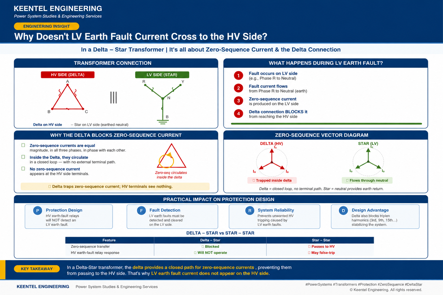
Learn why LV earth-fault current cannot cross a Delta-Star transformer, how zero-sequence current behaves, and what it means for protection design.

By SANDIP R PATEL
•
July 27, 2026
Learn how gas-insulated substations (GIS) improve safety, reliability, and space efficiency with 138 kV design, protection, insulation coordination, and real-world case studies.

By SANDIP R PATEL
•
July 25, 2026
Learn how Class I–IV electrical systems, defence-in-depth, standby and emergency power, DC systems, protection, and load transfer ensure nuclear power plant safety.