
A Coordinated Electric System Interconnection Review—the utility’s deep-dive on technical and cost impacts of your project.
Challenge: Frequent false tripping using conventional electromechanical relays
Solution: SEL-487E integration with multi-terminal differential protection and dynamic inrush restraint
Result: 90% reduction in false trips, saving over $250,000 in downtime
| Category | Metric |
|---|---|
| VPP capacity (Lunar Energy) | 650 MW |
| Lunar funding raised | US$232 million |
| Data center BESS example | 31 MW / 62 MWh |
| ERCOT grid-scale batteries | 15+ GW |
| LDES tenders (H1 2026) | Up to 9.3 GW |
| Lithium-ion share of LDES by 2030 | 77% |
| FEOC initial threshold | 55% |
| BESS tariff rate (2026) | ~55% |
| Capacity gain from analytics | 5–15% |
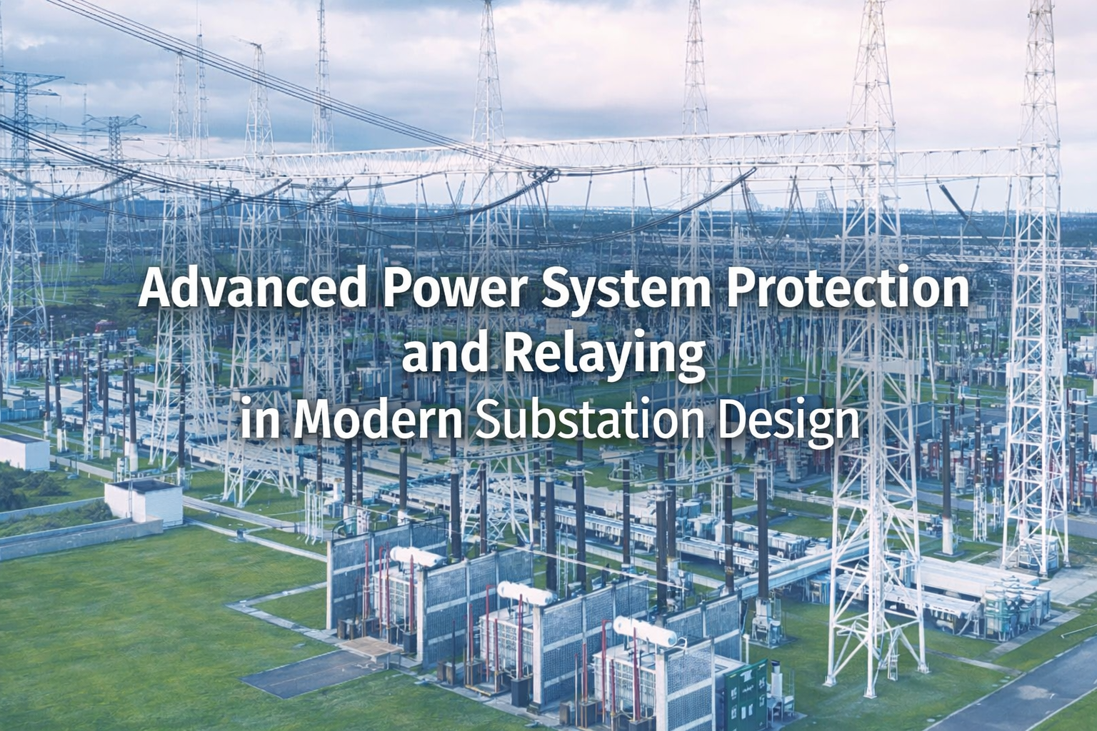
Advanced Power System Protection and Relaying in Modern Substation Design
Feb 8,2026 | blog
Engineering Principles, SCADA Integration, and Protection Architecture for Reliable Power Systems
Modern electrical substations are the backbone of reliable power transmission and distribution networks. As the power grid becomes increasingly complex with renewable integration, inverter-based resources, digital automation, and cybersecurity concerns substation protection design must evolve to ensure system reliability, safety, and operational resilience.
Protection engineering is one of the most critical disciplines in substation design. It ensures that faults are detected instantly and isolated with minimal disruption to the rest of the power system. Without properly designed protection schemes, faults could propagate across the network, damage expensive equipment, and cause widespread outages.
At Keentel Engineering, substation protection design integrates advanced relaying, SCADA systems, fault analysis methodologies, and modern digital relay technologies to create highly reliable protection architectures for transmission and distribution networks.
This article explores the engineering principles behind modern protection systems, fault detection methods, relay technologies, SCADA integration, and protection design considerations used in high-voltage and medium-voltage substations.
1. Fundamentals of Power System Protection
Power system protection is a specialized engineering discipline focused on detecting abnormal operating conditions and isolating the faulted section of the system before equipment damage occurs.
The fundamental objectives of protection engineering include:
- Prevent equipment damage
- Maintain power system stability
- Minimize service interruptions
- Protect personnel and the public
- Maintain operational reliability
A protection system monitors electrical quantities such as:
- Current
- Voltage
- Frequency
- Power flow
- Impedance
- Temperature
- Phase angles
These measurements are continuously analyzed by protective relays to determine whether the system is operating normally or experiencing abnormal conditions.
If a fault occurs, the relay sends a trip command to a circuit breaker, isolating the faulted equipment or transmission line.
This automated response typically occurs within milliseconds, preventing cascading failures across the power system.
2. Common Faults in Electrical Power Systems
Electrical faults are abnormal operating conditions where current deviates significantly from normal levels.
Faults occur due to:
- Lightning strikes
- Insulation breakdown
- Equipment failure
- Vegetation contact
- Animals or birds bridging conductors
- Mechanical damage to transmission lines
- Human error
- Severe weather events
Faults are classified into several categories.
Symmetrical Faults
These involve balanced three-phase faults and represent the most severe fault conditions.
Examples include:
- Three-phase short circuits
- Three-phase-to-ground faults
Although symmetrical faults produce the highest currents, they are relatively rare.
Unsymmetrical Faults
These are far more common in power systems.
Typical unsymmetrical faults include:
- Single line-to-ground faults (70-80% of faults)
- Line-to-line faults
- Double line-to-ground faults
Unsymmetrical faults produce unbalanced currents and require analysis using symmetrical components.
High Impedance Faults
These occur when conductors contact high resistance surfaces such as asphalt or vegetation.
Characteristics include:
- Low fault current
- Difficult detection
- Intermittent arcing behavior
Advanced detection techniques are required for high-impedance faults.
3. Key Performance Requirements of Protection Systems
An effective protection scheme must meet several performance criteria.
1. Speed
Protection must isolate faults rapidly to prevent equipment damage.
Typical relay operation time:
- 10 milliseconds to a few cycles
2. Selectivity
Protection must isolate only the faulted section of the network.
This prevents unnecessary outages.
3. Sensitivity
Relays must detect even small faults, particularly in high-impedance fault conditions.
4. Reliability
Protection systems must operate correctly whenever required.
Reliability is achieved through:
- Redundant protection schemes
- Backup relays
- Independent tripping paths
5. Security
Protection must not operate incorrectly during normal system conditions.
False trips can cause unnecessary outages.
4. Key Components of Substation Protection Systems
Modern substation protection architecture includes multiple interconnected components.
Protective Relays
Relays act as the decision-making devices of the protection system.
They analyze electrical quantities and determine whether a fault exists.
Current Transformers (CTs)
CTs reduce high system currents to standardized secondary currents.
Typical secondary ratings:
- 1 A
- 5 A
CTs allow relays to safely measure system current.
Voltage Transformers (VTs)
Voltage transformers reduce system voltage to safe measurement levels.
Typical relay input voltage:
- 120 V
- 69 V (phase-neutral)
Circuit Breakers
Circuit breakers physically interrupt fault current when commanded by protective relays.
Modern breakers operate in less than 3 cycles.
Auxiliary Power Supply
Protection systems typically operate using DC battery systems to ensure operation even during power loss.
Communication Systems
Protection systems communicate using:
- Fiber optic channels
- Pilot protection
- SCADA networks
- IEC 61850 communication
5. Protection Zones in Substation Design
Power systems are divided into protection zones.
Each zone is monitored by a specific set of protective relays.
Typical zones include:
- Generator protection zone
- Transformer protection zone
- Busbar protection zone
- Transmission line protection zone
- Feeder protection zone
Zones are designed with overlapping boundaries to ensure no section of the system is left unprotected.
This overlap prevents blind spots in the protection scheme.
6. Primary and Backup Protection
Substation protection systems incorporate both primary protection and backup protection.
Primary Protection
Primary protection is the first line of defense.
It operates quickly to isolate faults within its designated zone.
Examples include:
- Differential protection
- Distance protection
- Overcurrent protection
Backup Protection
- Backup protection operates if the primary protection fails.
Two types of backup protection exist:
Local backup protection
- Located within the same substation.
Remote backup protection
- Located at adjacent substations.
Backup protection typically operates with intentional time delay.
7. Types of Protective Relays Used in Substations
Protective relays can be classified according to their operating principle.
Overcurrent Relays
Operate when current exceeds a predefined threshold.
Types include:
- Instantaneous overcurrent
- Time-delayed overcurrent
- Inverse time overcurrent
Differential Relays
Used to protect equipment such as:
- Power transformers
- Generators
- Busbars
They operate based on the difference between incoming and outgoing currents.
Distance Relays
Used primarily for transmission line protection.
Distance relays measure impedance between the relay location and the fault.
Common distance relay types:
- Impedance relay
- Reactance relay
- MHO relay
Directional Relays
Determine the direction of power flow.
Used to distinguish between:
- Forward faults
- Reverse faults
Frequency Relays
Used for system stability protection.
Applications include:
- Underfrequency load shedding
- Overfrequency protection
8. Evolution of Protective Relay Technology
Relay technology has evolved significantly over the past century.
Electromechanical Relays
These were the earliest protection devices.
Characteristics:
- Magnetic coils
- Moving mechanical parts
- Slower operation
Although reliable, they require significant maintenance.
Solid-State Relays
Introduced in the 1960s.
Features include:
- Electronic circuits
- No moving parts
- Faster response
Digital Relays
Use microprocessors and digital signal processing.
Capabilities include:
- Fault recording
- Event logging
- Advanced protection algorithms
Numerical Relays
The most advanced type of relay.
Features include:
- Multi-function protection
- Communication capability
- Self-diagnostics
- Remote monitoring
Numerical relays are now standard in modern substations.
9. SCADA Integration in Substation Protection
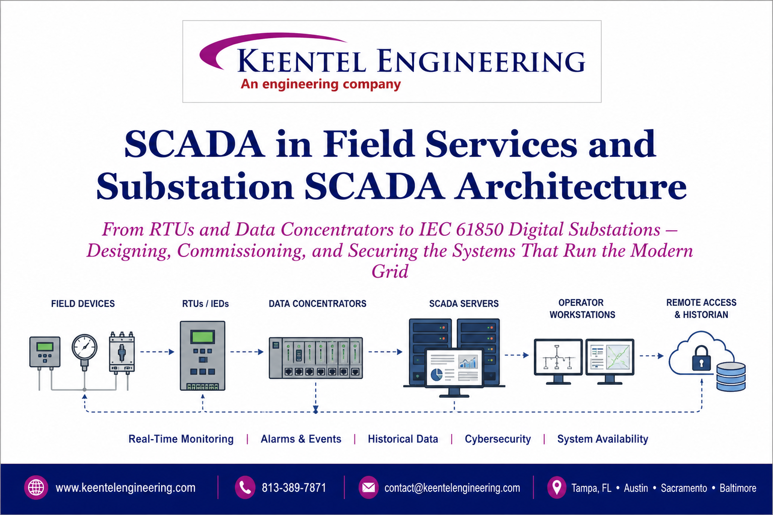
Supervisory Control and Data Acquisition (SCADA) systems provide centralized monitoring and control of substations.
SCADA architecture typically includes four levels.
Field Devices
These include sensors, actuators, and protection relays.
PLCs and RTUs
Programmable logic controllers and remote terminal units collect field data and transmit it to the control center.
Communication Network
Communication channels connect substations with control centers.
Technologies include:
- Fiber optic networks
- Microwave links
- Ethernet networks
SCADA Control Center
Operators monitor system status through graphical interfaces.
SCADA systems allow operators to:
- Monitor equipment status
- Issue remote switching commands
- Analyze fault events
- Maintain system reliability
10. Applications of SCADA in Substation Engineering
SCADA systems provide numerous operational benefits.
Key applications include:
- Real-time system monitoring
- Fault detection and isolation
- Load flow analysis
- Voltage control
- Alarm management
- Historical data analysis
- Automated system restoration
SCADA also enables predictive maintenance and system optimization.
11. Protection Coordination in Substation Engineering
Protection coordination ensures that protective devices operate in the correct sequence during faults.
Key principles include:
- Time grading
- Current discrimination
- Selective tripping
- Coordination between relays
Coordination studies are typically performed using power system simulation software.
12. Advanced Modeling and Fault Analysis
Protection engineering relies heavily on fault analysis.
Key techniques include:
Short-Circuit Analysis
Calculates fault current levels throughout the system.
Symmetrical Components
Used to analyze unbalanced faults.
Sequence networks include:
- Positive sequence
- Negative sequence
- Zero sequence
Impedance Modeling
Used in distance relay calculations.
Transient Analysis
Used to analyze generator and system dynamic behavior during faults.
13. The Future of Substation Protection Engineering
Modern substations are evolving toward digital substations.
Key future trends include:
- IEC 61850 communication protocols
- Process bus architecture
- Digital current transformers
- Synchrophasor measurements
- Cybersecure protection systems
- AI-based fault detection
These technologies will significantly improve power system reliability.
Conclusion
Substation protection engineering is a complex and essential discipline that ensures the safe and reliable operation of modern power systems. By combining advanced relay technologies, SCADA integration, fault analysis methodologies, and robust protection coordination engineers can design systems capable of responding to faults in milliseconds while maintaining system stability.
Keentel Engineering provides comprehensive substation protection design services, including relay coordination studies, fault analysis, SCADA integration, and digital protection system architecture for high-voltage and medium-voltage power systems.
Frequently Asked Questions (FAQs)
1. What is the main purpose of power system protection?
Power system protection detects abnormal conditions such as faults and isolates the affected portion of the system to prevent equipment damage and maintain system stability.
2. What are the most common types of faults in power systems?
The most common faults include:
- Single line-to-ground faults
- Line-to-line faults
- Double line-to-ground faults
- Three-phase faults
Single line-to-ground faults account for approximately 70-80% of all faults.
3. What is relay coordination?
Relay coordination ensures that protective relays operate in the correct sequence so that only the faulted section of the power system is isolated.
4. What is differential protection?
Differential protection compares currents entering and leaving equipment such as transformers or generators. If the currents differ beyond a threshold, the relay detects an internal fault.
5. What is distance protection?
Distance protection measures the electrical impedance between the relay location and a fault. It is widely used for transmission line protection.
6. What is the role of current transformers in protection systems?
Current transformers reduce high system currents to standardized levels so that protective relays can safely measure and analyze the current.
7. Why are voltage transformers required in protection systems?
Voltage transformers step down system voltage to safe measurement levels used by relays and monitoring devices.
8. What is a protection zone?
A protection zone is a section of the power system monitored by a specific protection scheme designed to detect and isolate faults within that zone.
9. What is backup protection?
Backup protection operates when the primary protection fails to isolate a fault. It provides redundancy and improves system reliability.
10. What are numerical relays?
Numerical relays are microprocessor-based protection devices capable of performing multiple protection functions, fault recording, and communication.
11. What is SCADA in substations?
SCADA is a control system used to monitor and manage substations remotely. It collects real-time data from field devices and allows operators to control equipment.
12. What are RTUs in a SCADA system?
Remote Terminal Units (RTUs) collect field data from substations and transmit it to the control center for monitoring and control.
13. What is protection reliability?
Protection reliability refers to the probability that a protection system will operate correctly during faults.
14. What is relay sensitivity?
Sensitivity refers to the ability of a relay to detect low-level faults.
15. What is protection security?
Security refers to the ability of a relay to avoid incorrect operation during normal system conditions.
16. What is the difference between instantaneous and time-delayed relays?
Instantaneous relays operate immediately when a fault occurs, while time-delayed relays operate after a predetermined delay.
17. What is the role of circuit breakers in protection systems?
Circuit breakers physically interrupt fault current when triggered by protective relays.
18. Why is redundancy used in protection systems?
Redundancy improves reliability by ensuring that backup systems operate if primary protection fails.
19. What is symmetrical component analysis?
Symmetrical component analysis is a mathematical method used to analyze unbalanced faults in three-phase power systems.
20. What are digital substations?
Digital substations use advanced communication protocols and digital measurement systems to improve protection, automation, and system monitoring

About the Author:
Sonny Patel P.E. EC
IEEE Senior Member
In 1995, Sandip (Sonny) R. Patel earned his Electrical Engineering degree from the University of Illinois, specializing in Electrical Engineering . But degrees don’t build legacies—action does. For three decades, he’s been shaping the future of engineering, not just as a licensed Professional Engineer across multiple states (Florida, California, New York, West Virginia, and Minnesota), but as a doer. A builder. A leader. Not just an engineer. A Licensed Electrical Contractor in Florida with an Unlimited EC license. Not just an executive. The founder and CEO of KEENTEL LLC—where expertise meets execution. Three decades. Multiple states. Endless impact.
Services

Let's Discuss Your Project
Let's book a call to discuss your electrical engineering project that we can help you with.
About the Author:
Sonny Patel P.E. EC
IEEE Senior Member
In 1995, Sandip (Sonny) R. Patel earned his Electrical Engineering degree from the University of Illinois, specializing in Electrical Engineering . But degrees don’t build legacies—action does. For three decades, he’s been shaping the future of engineering, not just as a licensed Professional Engineer across multiple states (Florida, California, New York, West Virginia, and Minnesota), but as a doer. A builder. A leader. Not just an engineer. A Licensed Electrical Contractor in Florida with an Unlimited EC license. Not just an executive. The founder and CEO of KEENTEL LLC—where expertise meets execution. Three decades. Multiple states. Endless impact.
Leave a Comment
Thank you for contacting us.
We will get back to you as soon as possible.
We will get back to you as soon as possible.
Oops, there was an error sending your message.
Please try again later.
Please try again later.
Related Posts
By SANDIP R PATEL
•
July 15, 2026
Learn how PJM markets, governance, stakeholder processes, and interconnection rules shape generation, storage, and large-load projects across North America.
By SANDIP R PATEL
•
July 14, 2026
Learn how AI data centers, cryptocurrency mining, and hydrogen electrolysis impact grid interconnection, EMT modeling, power quality, and system reliability.

By SANDIP R PATEL
•
July 13, 2026
Learn the complete ERCOT BESS interconnection process for TNMP and AEP Texas, including GINR, studies, SGIA, commissioning, fees, and project timelines.
By SANDIP R PATEL
•
July 13, 2026
Learn SCADA architecture, IEC 61850, RTUs, IEDs, DNP3, digital substations, commissioning, cybersecurity, and field services for modern power systems.
By SANDIP R PATEL
•
July 13, 2026
Learn how IEEE standards for grounding, protection, power quality, arc flash, and grid interconnection are applied in real engineering projects.
By SANDIP R PATEL
•
July 12, 2026
Complete PRC-028-1 guide for inverter-based resources. 12-chapter technical resource
By SANDIP R PATEL
•
July 11, 2026
Learn modern data center design, grid interconnection, electrical systems, cooling, commissioning, resilience, and operations for AI-ready facilities.

By SANDIP R PATEL
•
July 11, 2026
Master IEC 61850 SCADA engineering with ACSELERATOR Architect, GOOSE messaging, MMS, SCL files, server models, commissioning, and substation automation.
By SANDIP R PATEL
•
July 11, 2026
Learn power system protection and relaying, SCADA integration, relay coordination, fault analysis, grounding, and substation protection engineering.


