
A Coordinated Electric System Interconnection Review—the utility’s deep-dive on technical and cost impacts of your project.
Challenge: Frequent false tripping using conventional electromechanical relays
Solution: SEL-487E integration with multi-terminal differential protection and dynamic inrush restraint
Result: 90% reduction in false trips, saving over $250,000 in downtime
Navigating ERCOT Dynamic Model
Submission Requirements
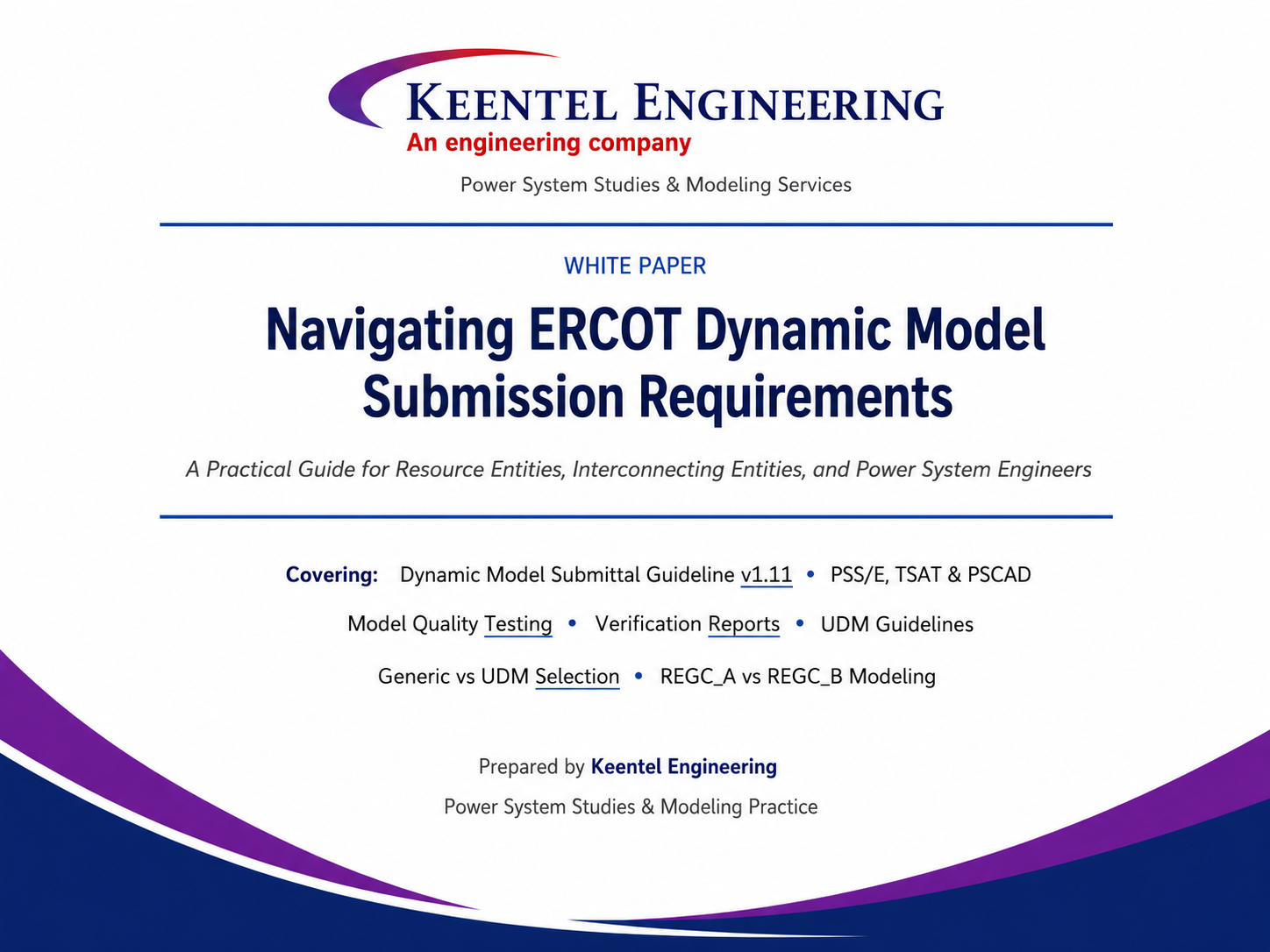
May 30, 2026 | White Paper
Quick Navigation
- About Keentel Engineering
- Executive Summary
- Section 1: ERCOT Dynamic Modeling Regulatory Landscape
- Section 2: PSS/E and TSAT Stability Models
- Section 3: PSCAD and Electromagnetic Transient Modeling
- Section 4: Model Quality Test (MQT)
- Section 5: Model Parameter Verification Reports
- Section 6: User-Defined Model (UDM) Guidelines
- Section 7: The Generic vs UDM Decision
- Section 8: REGC_A and REGC_B
- Section 9: Common Pitfalls
- Section 10: How Keentel Supports Your Project
- Frequently Asked Questions
- Case Studies
- Contact & Engagement
About Keentel Engineering
Who We Are
Keentel Engineering is a specialized power system studies and modeling firm serving Resource Entities, Interconnecting Entities, OEMs, developers, and utilities operating in ERCOT and across North American grid jurisdictions.
Keentel Engineering supports the renewable energy transition by delivering rigorous, defensible, and timely dynamic models, model quality test reports, verification reports, and grid interconnection studies. Our team blends deep simulation expertise across PSS/E, TSAT (DSATools), and PSCAD with practical knowledge of ERCOT Planning Guide and Nodal Operating Guide requirements.
From early Feasibility Interconnection Studies (FIS) through Quarterly Stability Assessment (QSA) entry, commissioning Part 3 approval, and the recurring MOD-026/027 obligations, Keentel Engineering acts as a single point of accountability for the technical artifacts ERCOT requires.
Service Areas
- Dynamic stability modeling in PSS/E and TSAT for synchronous, inverter-based, and hybrid resources.
- Electromagnetic Transient (EMT) modeling in PSCAD for IBRs, including weak-grid and subsynchronous studies.
- Model Quality Test (MQT) preparation with combined PSS/E + PSCAD + TSAT overlay plots.
- Model Parameter Verification reports for new commissioning, periodic refresh, MOD-026/027 cycles, and post-tuning field changes.
- User-Defined Model (UDM) review, debugging, and TSAT template (.tudm) preparation.
- Generic versus UDM model trade-off analysis with OEM coordination.
- RIOO-RS submittal preparation, file packaging, and dispute resolution support.
- Specialized weak-grid studies: Short Circuit Ratio (SCR) analysis, sub-synchronous resonance, REGC_A and REGC_B model selection and tuning.
- Advanced Grid Support (AGS) and Grid-Forming (GFM) inverter modeling, including hybrid AGS-ESR + non-AGS configurations.
- Hybrid facility modeling: wind plus solar, solar plus storage, IBR plus conventional, and resource plus large load arrangements.
Why Keentel Engineering
ERCOT model rejection — or worse, an undetected modeling defect that surfaces in commissioning — can delay a project by months and cost a developer millions of dollars in deferred revenue. Keentel Engineering invests in the test rigs, scripts, and quality checks that make first-time-right submissions the norm rather than the exception. Every report we deliver is structured around the exact rubric ERCOT applies during review.
Executive Summary
The Electric Reliability Council of Texas (ERCOT) operates one of the most renewable-intensive grids in the world. To safeguard reliability against the dynamic and transient phenomena introduced by hundreds of inverter-based resources, ERCOT enforces a uniquely rigorous framework of dynamic modeling, model quality testing, parameter verification, and EMT analysis. The framework is codified in the ERCOT Planning Guide, the Nodal Operating Guide, and the Dynamics Working Group (DWG) Procedure Manual.
This white paper distills the entirety of ERCOT's current dynamic model submission framework — current to the April 2026 release of the Dynamic Model Submittal Guideline (v1.11) — into a single, practical document. It is written for Resource Entity engineers, Interconnecting Entity project managers, OEM modelers, and senior leadership who need to understand both the technical requirements and the project-management implications of getting these submissions right.
Key Takeaways
Takeaway 1 — Verification Is Foundational
ERCOT will reject a model that does not match field equipment, regardless of how thoroughly it was tested. Verification is not optional documentation — it is the legal basis on which simulation results are trusted for system operation.
Takeaway 2 — Do Not Replace a UDM With a Generic Without OEM Endorsement
Generic models can be a legitimate engineering choice, but only when the OEM confirms the parameter set. Eighty percent of generic replacements reviewed by ERCOT show meaningful response deviation from the original UDM, and many fail Voltage Ride Through.
Takeaway 3 — PSCAD Is Where Weak-Grid Truth Lives
PSCAD is not a checkbox. It is the only platform in which the inner current control loop, PLL behavior, and weak-grid stability can be honestly assessed. ERCOT requires PSCAD for inverter-based resources, and the new checksheet is enforced.
Takeaway 4 — Hybrid Modeling Demands Combined MQTs
Hybrid facilities — and the new v1.11 clarifications around hybrid plus large load — require combined MQT submission whenever resources share a main power transformer or a master plant controller. Treating dissimilar components as separate plants when they are physically coupled is a common rejection trigger.
Takeaway 5 — Test AVR and PFR in the Model Before Building the Plant
The submission process is iterative. AVR and PFR field tuning during commissioning routinely forces a second round of model updates. Planning these adjustments into the model during the FIS stage — not at Part 3 — is the single biggest schedule risk a developer can control.
Section 1: The ERCOT Dynamic Modeling Regulatory Landscape
1.1 Why ERCOT Cares So Much About Dynamic Models
ERCOT operates an islanded interconnection of approximately 90,000 MW peak load, with renewable penetration that regularly exceeds 50 percent on a system-wide energy basis and frequently 100 percent during low-load hours. Unlike conventional synchronous generation, inverter-based resources (IBRs) do not provide natural inertia or fault-current contribution. Their dynamic behavior is entirely a function of firmware: ride-through logic, phase-lock loop behavior, current-limit priorities, and reactive support strategies are all programmable, and they vary substantially across manufacturers, firmware revisions, and even commissioning settings.
Misrepresenting that behavior in a planning model is not an academic concern. Two documented events — the 2021 Odessa Disturbance and its 2022 sequel — saw approximately 1,100 MW and 1,700 MW of solar generation respectively trip off the grid in response to single normally-cleared faults, well within the Voltage Ride Through (VRT) envelope the facilities were obligated to withstand. The root cause in both cases traced back to inverter protection settings that did not match the dynamic models on file with ERCOT and NERC.
1.2 The Governing Documents
| Document | Authority | Primary Subject | Update Cadence |
|---|---|---|---|
| ERCOT Nodal Protocols | Binding tariff | Resource obligations, settlement | Continuous (NPRRs) |
| Nodal Operating Guide | Binding tariff | VRT, frequency response, AVR, PFR | Continuous (NOGRRs) |
| ERCOT Planning Guide | Binding tariff | Sections 5.5 and 6.2: model submission, MQT, verification | Continuous (PGRRs) |
| DWG Procedure Manual | Stakeholder procedure | Detailed MQT test specifications, plot criteria | Periodic |
| Dynamic Model Submittal Guideline | Reference | Practitioner workflow, deliverables, file naming | Annual (v1.11 Apr 2026) |
| NERC MOD-026/027 | NERC standard | Excitation and turbine-governor model validation | 10-year cycle |
1.3 The Lifecycle of a Model Submittal
| Lifecycle Stage | Required Submission | Planning Guide Reference |
|---|---|---|
| Feasibility Interconnection Study (FIS) | PSS/E and PSCAD models; recommended MQT and AVR/PFR pre-check | PG 6.2(5)(a) |
| Entering Quarterly Stability Assessment (QSA) | Complete PSS/E, PSCAD, MQT overlay; Unit Model Validation (Hardware Benchmark) | PG 6.2(5)(c), (d) |
| Before Part 3 of Commissioning (IBRs) | MQT overlaying QSA model vs. as-built model response | PG 5.5(4) |
| Within 30 days of Part 3 Approval | Final PSS/E, PSCAD, TSAT models; combined MQT overlay; Verification Report | PG 5.5(6)(c) |
| 12 to 24 Months Post-Commissioning | Updated Verification Report; refreshed models if any drift | PG 5.5(5) |
| MOD-026/027 Cycle (every 10 years) | Re-submission of all models; Verification update; MQT overlay | PG 5.5(6)(b) |
| After Any Field Change | Pre-change MQT comparison; updated full package within 30 days | PG 5.5(6)(a) |
1.4 Where Submissions Land: The RIOO-RS Portal
All dynamic model submissions are uploaded to ERCOT's Resource Integration and Ongoing Operations — Resource Services (RIOO-RS) portal as zip-file attachments to an Attachment-Only Change Request. Compressed files larger than approximately 60 MB must be split. File naming follows a strict convention:
- (SITECODE)_DYNAMIC_(YYYY-MM-DD).zip — for the PSS/E and TSAT model package.
- (SITECODE)_PSCAD_(YYYY-MM-DD).zip — for the PSCAD model package.
Keentel Practice Note
Keentel Engineering maintains a RIOO-RS submission checklist and a digital-certificate workflow that prevents the most common procedural rejections: missing files, mismatched dates, oversized zip archives, and incomplete model templates. This single artifact has saved client projects an average of four to six weeks of back-and-forth with ERCOT.
Section 2: PSS/E and TSAT Stability Models
2.1 The Role of PSS/E in ERCOT Planning
Siemens PTI PSS/E is the workhorse of ERCOT Transmission Planning. Its current required versions are PSS/E 35 and PSS/E 36 — both must be supplied because ERCOT is mid-transition. For user-defined models (UDMs), separate .dll files compiled against each version are required.
Required PSS/E Deliverables
- .raw or .sav case file representing the plant up to the Point of Interconnection (POI).
- .dyr dynamic data file containing the dynamic model parameters.
- .dll file for User-Defined Models, compiled against the appropriate PSS/E version.
- Excel-format Dynamic Model Template (Universal template supports any UDM type).
- Python initialization scripts for switched shunts and on-load transformer taps.
- Model manual describing simulation setup, tunable parameters, and control block diagrams.
2.2 The Role of TSAT in ERCOT Operations
Where PSS/E serves Planning, PowerTech Labs TSAT (part of the DSATools package) serves ERCOT Operations. TSAT runs near-real-time stability analysis in the control room and supports Critical Clearing Time (CCT) scans, transfer analysis, and PMU data streaming. TSAT is required for any user-defined PSS/E model.
TSAT-Specific File Requirements
| File Type | Purpose | Notes |
|---|---|---|
| .dyr | Dynamic data file | Must interoperate with the PSS/E .dyr file |
| .dll | Compiled UDM code | Separate from PSS/E DLL |
| .tudm | TSAT template UDM | Defines model structure only; no project-specific data |
| .raw | Power flow case (bus-number format) | One package using bus numbers |
| .pfb | Power flow case (equipment-name format) | Second package using equipment names with spaces |
| .mon, .dat, .swi | Monitor, data, switching files | For test scenarios |
TSAT Equivalence Requirement
ERCOT requires the TSAT model to produce results that are 100 percent identical when run in bus-number format versus equipment-name format. This is a non-negotiable acceptance criterion. Keentel Engineering verifies dual-format equivalence as a standard pre-submission check.
2.3 Standard Library Models vs. User-Defined Models
| Attribute | Standard Library / Generic Model | User-Defined Model (UDM) |
|---|---|---|
| Source | Built into PSS/E and TSAT | Compiled .dll provided by OEM |
| Fidelity | Lower — approximated controls | Higher — closer to actual firmware |
| Setup effort | Low to medium | Medium to high |
| Weak-grid performance | Often fails at SCR below 2 | Usually well-behaved if OEM-tuned |
| Software-version maintenance | Minimal | DLL must be recompiled per version |
| MOD-026/027 acceptance | Yes, with caveats | Yes — preferred |
| VRT compliance risk | Higher (Odessa-class failures) | Lower if maintained |
| TSAT model required | No | Yes — must be supplied |
Section 3: PSCAD and Electromagnetic Transient Modeling
3.1 Why PSCAD is Required for Inverter-Based Resources
Positive-sequence stability tools like PSS/E and TSAT do not faithfully represent the inner current-control loop of a voltage-source converter, nor the dynamics of the Phase Lock Loop (PLL), nor the millisecond-scale interaction between inverter protection and grid disturbances. These are precisely the phenomena that drove the Odessa events. PSCAD is an Electromagnetic Transient (EMT) simulator that represents the network in full three-phase detail at time steps of 10 to 20 microseconds.
3.2.1 Accuracy Requirements (Highlights)
- The model must represent the full detailed inner control loop of the power electronics — no transient-stability approximations.
- Validation requires either use of actual hardware code or comparison with measured device response, including a small-signal frequency sweep over 5 to 55 Hz.
- Models assembled from PSCAD master library standard blocks are explicitly flagged as introducing unacceptable approximations.
- PLL loss-of-synchronism, phase-angle-jump, and anti-islanding protections must either be disabled or have their necessity justified by the OEM.
- DC bus dynamics, including capacitor discharging and protection, must be modeled.
3.2.2 Usability Requirements (Highlights)
- The model must initialize itself and ramp to full output without external simulation engineer input.
- It must accept external Pref, Qref, and Vref values via single-parameter adjustment.
- A 10-second simulation must complete in under approximately 300 seconds on a typical workstation.
3.2.3 Efficiency Requirements (Highlights)
- Model must be embedded in the ERCOT PSCAD Template.
- It must compile with Intel Fortran v15+ and Microsoft Visual Studio 2015+, including support for the Intel OneAPI HPC compiler.
- Both 32-bit and 64-bit Fortran libraries must be provided.
- Compatibility with PSCAD v5.0.1 and higher is required.
Keentel Experience
The single most common PSCAD rejection cause Keentel Engineering observes is models assembled from standard library blocks rather than derived from hardware code. The behavior often looks correct under nominal conditions but diverges sharply under fault, weak-grid, or low-temperature operating points.
3.3 Weak-Grid Studies and Subsynchronous Resonance
As ERCOT's renewable fleet has grown in the Panhandle, South Texas, and West Texas, more interconnection points have moved into SCR territory of 2 or below. For any plant with an interconnection SCR of 2 or lower, PSCAD studies — using OEM-provided source-code-based models — are required, and Keentel Engineering routinely performs them.
Section 4: The Model Quality Test (MQT)
4.1 Purpose and Test Catalog
The Model Quality Test is the engineering rubric by which ERCOT determines whether a submitted model is fit for use in system studies. The MQT report must overlay PSS/E, PSCAD, and TSAT model responses on the same plot axes whenever multiple platforms apply.
| Test | Initialization | What It Demonstrates |
|---|---|---|
| Flat-start | 100% dispatch, steady state | Correct model initialization, no drift |
| POI Voltage Step Down 3% | 100% dispatch, 0 MVAr at POI | Reactive injection on voltage dip |
| POI Voltage Step Up 3% | 100% dispatch, 0 MVAr at POI | Reactive absorption on voltage rise |
| HVRT Leading | 100% dispatch, 0.95 pf leading | High-voltage ride-through with leading initialization |
| HVRT Lagging | 100% dispatch, 0.95 pf lagging | High-voltage ride-through with lagging initialization |
| HVRT Preferred (NOGRR-245) | Per NOGRR-245 | Updated VRT envelope compliance |
| LVRT Leading | 100% dispatch, 0.95 pf leading | Low-voltage ride-through, leading |
| LVRT Lagging | 100% dispatch, 0.95 pf lagging | Low-voltage ride-through, lagging |
| Voltage Dip Test (Preferred LVRT) | Per NOGRR-245 | Updated LVRT envelope compliance |
| Freq Step Down 0.3 Hz, No Headroom | 80% dispatch | Correct non-response when uncurtailed |
| Freq Step Down 0.3 Hz, With Headroom | 80% dispatch, curtailed flag set | Power increase when curtailed |
| Freq Step Up 0.3 Hz | 80% dispatch | Power reduction |
| Short Circuit Ratio (SCR) Test | 100% dispatch | Stable behavior down to SCR = 1.2 |
| Phase Angle Jump (IBR PSCAD) | 100% dispatch | Ride-through angle jumps without trip |
4.2 MQT Scenarios by Facility Type (v1.11 Clarifications)
| Facility Type | Required MQT Scenarios |
|---|---|
| Standalone Non-ESR | 100% generation |
| Standalone ESR | ESR charging (max withdrawal); ESR discharging (max injection) |
| Hybrid Non-ESR + ESR | ESR charging alone; combined max injection |
| Hybrid Wind + Solar | Solar only; wind only; combined solar + wind |
| Hybrid IBR + Conventional | IBR only; IBR + conventional |
| Resource + Large Load | Large Load only; max withdrawal; max injection (Load offline) |
| Self-Limiting Facility (SLF) | All scenarios must respect SLF total output limit |
| AGS-ESR Standalone | Flat-start, LVRT/HVRT (charge and discharge); AGS-specific tests at 0 MW and other dispatches |
| AGS-ESR Hybrid | All standard tests in three columns: AGS online only, non-AGS online only, both online |
Hybrid Facility Trap
Hybrid facilities must submit a combined MQT and combined models whenever the dissimilar components share a main power transformer OR a master plant controller. Submitting separate models when components are coupled is a guaranteed rejection.
4.4 The Headroom / No-Headroom Distinction
IRR models must default to no-headroom behavior. To represent a curtailed (headroom-enabled) state, the model must expose a flag or switch — not require manual adjustment of PMAX. For generic PSS/E models, the suggested approach is to set Dup = 0 in the plant controller model.
Section 5: Model Parameter Verification Reports
5.1 Purpose and Cadence
Verification Reports are required at four points: within 30 days of Part 3 commissioning approval; between 12 and 24 months after Part 3 approval; a minimum of every 10 years; and within 30 days of any setting change affecting dynamic response.
5.2 What a Verification Report Looks Like
ERCOT now provides a Verification worksheet directly inside the Dynamic Model Template package. The artifact must include for each tunable parameter: the model parameter name and value, the actual field equipment value in the same engineering units, the verification method, a yes/no match indication, and an explanation when values do not match.
5.3 Synchronous Plant Verification Parameters
| Parameter Class | Best Verification Method | Notes |
|---|---|---|
| Inertia (H) | Commissioning / delivery reports | Sum all spinning masses; typical 3 to 9 MWs/MVA |
| Generator Electrical Parameters | Nameplate or delivery report | Generally do not change after delivery |
| Generator Saturation S(1.0), S(1.2) | Confirm if outside NERC ranges | S(1.0) 0.03 to 0.18; S(1.2) 0.20 to 0.85; ratio 2 to 8 |
| Protection Parameters | Engineer attestation, relay settings | Verify most-limiting setting across all relays |
| Exciter Gains | MOD-026 plus direct check | MOD-026 alone insufficient |
| Governor Parameters | MOD-027 or direct check | Standard |
| Power System Stabilizer | Direct equipment query | MOD-026/027 generally insufficient for PSS |
5.4 Inverter-Based Resource Verification
| IBR Verification Element | Acceptable Evidence |
|---|---|
| Protection Settings (Terminal) | OEM firmware documentation; parameter dump |
| Protection Settings (External Relays) | Engineer attestation comparing model to relay settings |
| Site-Specific Tunable Parameters | OEM attestation; commissioning report; parameter dump |
| Non-1:1 Parameters | Qualitative explanation of derivation method |
| PSCAD Model (Required If Generic PSS/E) | Verification must be performed on the PSCAD model |
Why MOD-027 Alone Is Not Enough
ERCOT explicitly states that MOD-026/027 small-signal tests are generally insufficient for verifying high-speed, large-signal, or voltage-ride-through response of inverter-based facilities. A defensible IBR Verification Report combines OEM attestation, commissioning records, and — where possible — high-speed PMU or DFR measurements compared against PSCAD simulation.
Section 6: User-Defined Model (UDM) Guidelines
6.1 Why ERCOT Publishes a UDM Specification
ERCOT and its DWG observed enough recurring failure modes — models that crashed when islanded, that depended on hidden initialization scripts, that wrote diagnostic files to disk during execution, or that could not run multiple instances in the same case — that the DWG published a formal UDM Guideline.
6.2 The Core UDM Requirements
Documentation: Detailed model manual including powerflow setup, tunable parameters, and a high-level control block diagram. Inter-model communication documentation showing data exchange between Plant Power Controller (PPC), WTG, and STATCOM models.
Software Behavior: Parameter error checking; module-dependency enforcement; multiple-instance support; no file writes under default parameters; validation at multiple operating points (100%, 50%, and 10% dispatch).
PSS/E Implementation: DLL-only — no .OBJ or .LIB files. No hard-coded unit ID requirement. No artificial Qmin/Qmax constraints.
6.3 Practical UDM Review Process
| Review Dimension | Typical Findings |
|---|---|
| Documentation completeness | Missing control block diagrams; undocumented parameters |
| Initialization behavior | Power flow conditions outside the model's stable operating range |
| Switched-shunt and tap initialization | Missing Python init scripts; wrong starting position |
| Multi-instance behavior | Crashes when used at two sites simultaneously |
| TSAT dual-format equivalence | Equipment-name results diverge from bus-number |
| MQT at full operating range | Acceptable at 100%, unstable at 10% dispatch |
| Protection-model behavior | Instantaneous protection trips on numerical transients |
| Headroom toggle | Frequency response not implementable without recompiling |
Section 7: The Generic vs UDM Decision
7.1 The Case For and Against Generic Models
Generic (WECC standard library) models offer real benefits — they ship with the simulation tool, do not require recompilation, and are well-documented. But ERCOT's October 2019 stakeholder presentation documented that of approximately 27 IRR sites that had migrated from UDM to generic: roughly 80% showed significant differences in dynamic response, many failed Voltage Ride Through, and generic models showed numerical instability at SCR below 2.
ERCOT Position on Generics
ERCOT does not prohibit generic models, but it has stated publicly that it will reject generic models that do not perform reasonably or that fail Voltage Ride Through, regardless of how widely the model is used elsewhere.
7.2 Why Generic Models Fail
WECC generic models encode a simplified abstraction of inverter behavior. The internal current control loop is not modeled. The PLL is not modeled. When a consultant constructs a generic equivalent purely from MOD-026/027 small-signal measurements, the resulting parameter set captures only slow response. Fast transient behavior — exactly the behavior that determines VRT compliance — is essentially guessed.
7.4 Keentel Engineering's Decision Framework
| Condition | Recommended Path |
|---|---|
| Plant has SCR > 5 at POI, OEM supports UDM | Maintain UDM |
| Plant has SCR between 2 and 5, OEM supports UDM | Maintain UDM; consider REGC_B if generic also kept |
| Plant has SCR < 2 | UDM required; PSCAD studies mandatory |
| OEM out of business, original UDM unsupported | Carefully tune generic with measured-response validation |
| MOD-026/027 study uses external consultant only | Validate any proposed generic against original UDM |
| Plant exhibits oscillatory behavior in operations | PSCAD investigation; do not migrate to generic |
| Hybrid facility with shared controller | UDM strongly preferred for the combined model |
Section 8: REGC_A and REGC_B — Choosing the Right Converter Interface Model
8.2 REGC_A — The Current-Source Model
REGC_A represents the generator-to-network interface as a controllable current source. In weak-grid conditions, a small change in injected current produces a large change in voltage, and the network solution can oscillate within an integration step — producing simulated voltage spikes with no physical meaning.
8.3 REGC_B — The Voltage-Source Model
REGC_B uses a voltage-source-behind-impedance interface, parameterized by Re, Xe, and a small firing-delay time constant Te. The Low Voltage Power Logic block of REGC_A is removed entirely; voltage-dependent current limiting is handled upstream via VDL tables.
8.4 Performance Comparison
| Short Circuit Ratio | REGC_A Behavior | REGC_B Behavior |
|---|---|---|
| ~30 (strong grid) | Stable, similar to REGC_B | Stable, similar to REGC_A |
| ~2 (moderate) | Stable but with unrealistic voltage spikes during fault | Stable, no spurious spikes |
| < 1 (very weak) | Numerically unstable; results meaningless | Converged; results usable |
Use REGC_B Wisely
REGC_B is a numerical improvement, not a substitute for vendor-specific EMT analysis. At SCR ≤ 2, only PSCAD with vendor code tells you whether a converged result reflects reality.
Section 9: Common Pitfalls and How to Avoid Them
9.1 Procedural Pitfalls
| Pitfall | Consequence | Mitigation |
|---|---|---|
| Missing PSCAD in updated submission | Rejection or rework | Submit all models every time, dated |
| Wrong filename convention | Difficulty tracking, possible rework | Use (SITECODE)_DYNAMIC_(date).zip strictly |
| Oversized zip > 60MB | Upload fails | Split into multiple zips |
| No Python init scripts for shunts | Wrong initial conditions, MQT fails | Always provide initialization scripts |
| Unit count or sizes do not match registration | Direct rejection | Cross-check RIOO-RS Unit Attributes |
| Different aggregation in PSS/E vs TSAT | Rejection | Match aggregation exactly |
9.2 Technical Pitfalls
| Pitfall | Consequence | Mitigation |
|---|---|---|
| IRR model not set to no-headroom default | Incorrect frequency response, rejection | Default to no-headroom; expose flag for curtailment |
| PSCAD using PSCAD master library blocks | Inaccurate fault response | Use OEM hardware-code-based PSCAD model |
| Anti-islanding / PAJ protection left active | Spurious trips, VRT failure | Disable unless OEM confirms necessity |
| Generic model substituted without OEM endorsement | 80% chance of response divergence, VRT failure | Maintain UDM or get OEM-validated generic |
| Hybrid components submitted separately when coupled | Rejection | Combined MQT for shared transformer or controller |
| TSAT bus-number and equipment-name results differ | Rejection | Verify dual-format equivalence pre-submission |
| AVR step test not run during planning | Tuning required at commissioning, model rework | Test AVR/PFR on the model before FIS |
9.3 Documentation Pitfalls
| Pitfall | Consequence | Mitigation |
|---|---|---|
| Verification Report citing only MOD-027 for IBR | Insufficient evidence, rejection | Add OEM attestation and PSCAD comparison |
| Missing model manual | Reviewer unable to interpret, rejection | Provide manual or PSS/E reference for std lib |
| No combined MQT overlay plot | Rejection (required since June 2023) | Always overlay PSS/E, TSAT, PSCAD on one axis |
| Sample test files not included | Reviewer cannot reproduce, rejection | Include all .sav, .dyr, .dll, PSCAD project |
Section 10: How Keentel Engineering Supports Your Project
10.1 Service Tiers
| Tier | Scope | Typical Engagement |
|---|---|---|
| Advisory | Strategy, decision frameworks, regulator interface | Discrete consults; 1-4 weeks |
| Standard | Single-site dynamic model, MQT, verification | 8-16 weeks per submission cycle |
| Comprehensive | Multi-site fleet, MOD-026/027 program management | Ongoing retainer; 6-24 months |
| EMT Specialty | PSCAD weak-grid, SSR, AGS modeling | Targeted; 4-12 weeks per study |
| Hybrid Resource Specialty | Wind+solar+ESR or resource+large load combined modeling | 12-20 weeks per facility |
10.2 What a Typical Keentel Engagement Looks Like
- Project intake: review of facility one-line, OEM manuals, prior submissions, ERCOT correspondence.
- Gap analysis: comparison of current model package against the ERCOT Guideline v1.11 checklist.
- Model build or audit: PSS/E, TSAT, and PSCAD models built or revised in their respective templates.
- MQT execution: DMVIEW and PMVIEW runs, combined overlay plot generation, anomaly investigation.
- Verification: parameter-by-parameter comparison with field equipment, OEM attestation gathering, documentation.
- Submission package assembly: RIOO-RS zip preparation, filename validation, attachment list.
- Reviewer-correspondence support: response to ERCOT comments, model updates, resubmission.
- Post-acceptance maintenance: 12-24 month refresh, MOD cycle planning, change-management for field updates.
Frequently Asked Questions
Q1. When can I use a generic (WECC standard library) model instead of the OEM's User-Defined Model?
When the OEM has confirmed in writing that the proposed generic parameter set accurately represents their equipment, and you have validated that the generic produces equivalent response across the full MQT test catalog. Generics are most defensible when: (1) the OEM endorses the generic for a brand-new project; (2) the original UDM is no longer maintained; (3) the interconnection SCR is greater than 5. Generics are most dangerous when used as a labor-saving substitute by a third-party MOD-026/027 consultant building from small-signal data alone.
Q2. What is the practical difference between REGC_A and REGC_B, and when should I use each?
REGC_A is a current-source model; REGC_B is a voltage-source model. REGC_A works well in strong-grid conditions but becomes numerically problematic in weak grids — ERCOT's benchmarks show it becoming unstable at SCR below 1, with unrealistic voltage spikes at SCR around 2. REGC_B is well-behaved at low SCR, but is a numerical improvement, not a fidelity improvement. At SCR ≤ 2, vendor-specific PSCAD analysis is still required regardless of which model is used.
Q3. What goes wrong most often during commissioning, and how do I prevent it?
AVR and PFR field tuning during Part 2 of commissioning conflicts with the performance objectives demonstrated in the MQT, forcing model updates and resubmission — typically costing four to twelve weeks. Prevention: during the FIS and QSA stages, run an AVR voltage-step test and a PFR frequency-step test on the model. If either fails in simulation, fix the model before any concrete is poured.
Q4. What is required for a hybrid facility, and how does v1.11 change things?
If dissimilar components share a main power transformer or a master plant controller, a combined MQT and combined model package are required. For wind plus solar: solar-only, wind-only, and combined scenarios. For IBR plus ESR: standalone ESR charging and combined maximum injection. For resource plus large load: large-load-only, maximum withdrawal, and maximum injection (load offline). For AGS-ESR hybrid: three scenario columns across AGS-online-only, non-AGS-online-only, and both-online.
Q5. How often do I have to submit a Verification Report, and what does ERCOT actually want to see in one?
Required at four points: within 30 days of Part 3 approval; between 12 and 24 months after; every 10 years minimum; and within 30 days of any dynamic setting change. ERCOT wants: a narrative describing how and when parameters were checked, a table comparing model parameters with field settings in matching engineering units, and supporting evidence (screenshots preferred, OEM attestations accepted).
Q6. What is the no-headroom default, and why does ERCOT insist on it?
ERCOT requires IRR models to default to no-headroom because when PGEN is less than PMAX for a renewable plant, it is because of insufficient wind or solar — not curtailment. The plant has no fuel reserve to draw from in a low-frequency event. If a model treats the PGEN-to-PMAX gap as headroom by default, every system study will over-estimate available primary frequency response — lulling operators into trusting reserves that do not exist.
Q7. Can I just use one PSCAD model across all my similar sites, or do I need a unique model per facility?
The same underlying PSCAD model with site-specific parameterization. Site-specific items include main power transformer impedance and rating, collector system equivalent impedance, number and rating of inverters, plant-controller gain and droop settings, and protection thresholds. A developer with eight sites using the same inverter platform should maintain eight separate PSCAD project files — each with site-specific parameters — but only one underlying inverter component model.
Q8. How do I demonstrate that my IBR can ride through a weak-grid event?
Four artifacts: (1) a PSCAD model built from OEM hardware code including the inner-current-control loop and PLL implementation; (2) an SCR MQT test demonstrating stable behavior from SCR = 8 down to SCR = 1.2; (3) a Phase Angle Jump test in PSCAD; (4) where SCR is at or below 2, a vendor-specific facility study confirming inner-control-loop bandwidth coordination with the PLL. Common failures include PLL loss-of-synchronism, phase-angle-jump, or anti-islanding protection left active.
Q9. What do I have to submit when I change a setting in the field, and what is the timeline?
Before making a field change at an operational IBR: submit a pre-change MQT overlay comparing proposed vs. as-built model response (both PSS/E and PSCAD), with email subject 'IBR Proposed Modification' to dynamicmodels@ercot.com. After the change is approved, within 30 days submit final PSS/E, PSCAD, and TSAT models to RIOO-RS with a combined MQT overlay and updated Verification Report. For synchronous facilities, the pre-change MQT comparison is not required.
Q10. We are a small developer / a first-time Resource Entity. What is the realistic timeline and cost?
A standalone 200 MW solar facility using vendor-supported UDMs typically requires 8 to 12 weeks from FIS through Part 3 commissioning. A hybrid facility with shared main transformer typically requires 14 to 20 weeks. The first-time risk factor that disproportionately impacts new developers is OEM responsiveness. Standard engagements range from the mid five figures to the low six figures USD for a single site. The largest hidden cost is not the modeling work — it is the schedule cost of an avoidable model rejection deferring commercial operations by months.
Case Study 1: Generic Model Substitution Triggers VRT Failure
Client Profile
A 300 MW solar PV facility in the West Texas region, commissioned in 2017. Originally interconnected with a vendor-supplied UDM in PSS/E and a corresponding TSAT model.
The Triggering Event
The Resource Entity engaged a third-party MOD-026/027 consultant for the 10-year compliance cycle. The consultant proposed replacing the UDM with a WECC generic model set (REGC_A, REEC_A, REPC_A) on the rationale of reduced ongoing maintenance burden. The generic parameters were derived from MOD-026/027 small-signal test data and submitted to ERCOT as the updated dynamic model.
What ERCOT Found
The Voltage Step Down 3% test showed reactive injection only 40 percent of the UDM magnitude, with response time four times slower. The HVRT Leading test showed the generic tripping at approximately 1.18 per unit voltage, while the original UDM rode through beyond 1.20 per unit. The SCR test showed the generic becoming oscillatory at SCR = 1.8, while the original UDM remained stable down to SCR = 1.2. ERCOT rejected the submission.
Resolution
Keentel Engineering reverted to the original UDM, recompiled for PSS/E v35 and v36, supplemented with a refreshed TSAT model and a PSCAD model built from OEM hardware code. Every test passed, including SCR = 1.2 stability. The resubmission was accepted on first review — 9 weeks from Keentel engagement to ERCOT acceptance. The model was the problem, not the plant.
Case Study 1 — Key Lesson
Generic models built from inadequate validation data, without OEM involvement, are bad. A properly tuned and OEM-endorsed generic can be a defensible engineering choice; a consultant-built generic derived only from MOD-026/027 small-signal data is not.
Case Study 2: Weak-Grid Oscillation at a Panhandle Wind Plant
Client Profile
A 350 MW wind facility in the ERCOT Panhandle region, interconnected at a 345 kV point with a Short Circuit Ratio of approximately 1.6 under the most-binding contingency.
The Issue and Investigation
During QSA-stage stability assessment, ERCOT observed sustained ~3 Hz oscillations in PSS/E simulations. Switching to REGC_B dampened the oscillations materially but did not eliminate them. A PSCAD case using OEM source-code-based models showed an initial transient that damped within ~400 milliseconds, with real residual oscillation. Frequency-domain analysis identified the residual oscillation as PLL interaction at a specific bandwidth, and the OEM confirmed that enabling a firmware 'weak-grid option' setting would eliminate it.
Resolution
The OEM committed to enabling the weak-grid option at commissioning. Keentel Engineering rebuilt the PSCAD model with that setting active and produced a combined PSS/E (REGC_B), PSCAD, and TSAT overlay showing damped, stable response. ERCOT accepted the QSA submission and the plant proceeded to construction on its original schedule.
Case Study 2 — Key Lesson
Weak-grid behavior at SCR ≤ 2 cannot be reliably assessed in PSS/E or TSAT alone. The only defensible analysis is OEM-source-code PSCAD with vendor coordination on inner-loop and PLL settings.
Case Study 3: A Hybrid Solar-Plus-Storage-Plus-Large-Load Facility
Client Profile
A first-of-kind hybrid facility in South Texas: 250 MW solar PV, 100 MW / 400 MWh battery energy storage (AGS / Grid Forming), and a co-located 75 MW electrolyzer load for green hydrogen production — all sharing a single 345 kV main power transformer and a single master plant controller.
The Modeling Challenge
Because all components share both a main transformer and a master controller, the v1.11 Guideline requires a combined MQT and combined model submission. Three distinct OEMs — solar inverters, battery inverters, and electrolyzer power conversion — each with its own UDM and PSCAD model — had to be integrated into a single combined model. Total individual simulations: 142 across PSS/E, TSAT, and PSCAD.
Approach and Resolution
Keentel Engineering convened a coordination workshop with all three OEMs, built combined PSS/E and TSAT models over six weeks, then spent eight weeks building the combined PSCAD model — requiring OEM license negotiations and resolution of cross-vendor Fortran compilation conflicts. The final Combined Model Submittal Package included a 380-page joint MQT report, three Unit Model Validation reports, and a master plant controller manual. ERCOT accepted the package after one round of clarifying questions.
Case Study 3 — Key Lesson
Hybrid facilities require not just modeling skill but project-management skill. The largest schedule risk is organizational: coordinating multiple OEMs to deliver compatible, interoperable model components on a single timeline.
Appendix: Quick-Reference Submission Checklist
A.1 PSS/E and TSAT Package
- PSS/E v35 model (.raw or .sav, .dyr, .dll for UDM).
- PSS/E v36 model (.raw or .sav, .dyr, .dll for UDM).
- PSS/E model in Excel Template format (Universal template for UDMs).
- TSAT model with .raw, .dyr, .dll, .tudm files (if UDM).
- TSAT bus-number example case and equipment-name example case (with space character).
- TSAT .pfb file plus .mon, .dat, .swi files.
- Python initialization scripts for switched shunts and on-load transformer taps.
- Model manual or PSS/E manual reference for standard library models.
- Unit count, size, and names match RIOO-RS registration exactly.
- IRR models default to no-headroom; headroom flag exposed.
A.2 PSCAD Package (IBRs)
- PSCAD model embedded in ERCOT PSCAD Template.
- Completed PSCAD Guideline Checksheet.
- PSCAD model manual.
- 32-bit and 64-bit Fortran libraries (where applicable).
- Unit Model Validation (Hardware Benchmark) report — required if commissioned after 3/1/2021.
A.3 Model Quality Test (MQT) Report
- Combined overlay plot of PSS/E, PSCAD, and TSAT responses (TSAT if UDM).
- All required test scenarios per facility type.
- Test case files (.sav/.raw, .dyr, .dll, PSCAD project).
- Honest disclosure of any test that fails, with corrective-action plan.
A.4 Verification Report (Or Template Worksheet)
- Narrative describing how and when parameters were checked.
- Parameter-by-parameter comparison table with matching units.
- Verification method noted for each parameter.
- Supporting evidence (screenshots preferred, OEM attestation accepted).
- Protection model verification, including PSS/E protection if PSCAD is primary model.
A.5 RIOO-RS Submission Mechanics
- Files named: (SITECODE)_DYNAMIC_(YYYY-MM-DD).zip and (SITECODE)_PSCAD_(YYYY-MM-DD).zip.
- Zip files under approximately 60 MB each (split if larger).
- Attachment-Only Change Request in RIOO-RS.
- All models submitted — even unchanged ones — with dates indicating which are new.
- TSP notified of the change.
Contact Keentel Engineering
This white paper has surveyed a complex and continuously evolving framework. ERCOT updates its Planning Guide, Operating Guide, and DWG Procedure Manual several times per year, and individual project circumstances frequently require interpretation that goes beyond the published guidance.
Keentel Engineering invites Resource Entities, Interconnecting Entities, OEMs, developers, and asset managers to reach out for a no-commitment scoping conversation about specific project needs. Our team is structured to support engagements ranging from single targeted consultations through multi-year, multi-site MOD-026/027 program management.

About the Author:
Sandip "Sonny" R. Patel, P.E.
IEEE Senior Member · Founder & CEO, Keentel Engineering
In 1995, Sonny Patel earned his Electrical Engineering degree from the University of Illinois. But degrees don't build legacies — action does.
For three decades, he has worked the power industry from every side of the table: 16 years as a utility engineer at Exelon/Commonwealth Edison; generation leadership across hydroelectric, industrial steam turbine, and a 9 GW renewable fleet; NERC Regional Entity Senior Compliance Engineer and Audit Team Lead, auditing some of the nation's largest utilities; and testing and commissioning lead on equipment up to 765 kV — the very top of the North American grid.Utility. Generator. Regulator. Consultant. Few engineers have seen all four seats. Fewer still have sat in them.
His experience spans nuclear, hydro, conventional generation, renewables, oil and gas, mining — and today's data centers, where he is authoring a three-book series on data center design. He is a Licensed Professional Engineer in six states and a Licensed Electrical Contractor in Florida (Unlimited EC) — he doesn't just design the work; he's qualified to stand behind its execution.Today, as Founder and CEO of Keentel Engineering, Sonny leads a nationwide team of engineers delivering substation design, power system studies, NERC compliance, and commissioning — done right, coast to coast.Three decades. Every side of the table. One standard: accountable engineering.
Services

Let's Discuss Your Project
Let's book a call to discuss your electrical engineering project that we can help you with.
About the Author:
Sandip "Sonny" R. Patel, P.E.
IEEE Senior Member · Founder & CEO, Keentel Engineering
In 1995, Sonny Patel earned his Electrical Engineering degree from the University of Illinois. But degrees don't build legacies — action does.
For three decades, he has worked the power industry from every side of the table: 16 years as a utility engineer at Exelon/Commonwealth Edison; generation leadership across hydroelectric, industrial steam turbine, and a 9 GW renewable fleet; NERC Regional Entity Senior Compliance Engineer and Audit Team Lead, auditing some of the nation's largest utilities; and testing and commissioning lead on equipment up to 765 kV — the very top of the North American grid.
Utility. Generator. Regulator. Consultant. Few engineers have seen all four seats. Fewer still have sat in them.
His experience spans nuclear, hydro, conventional generation, renewables, oil and gas, mining — and today's data centers, where he is authoring a three-book series on data center design. He is a Licensed Professional Engineer in six states and a Licensed Electrical Contractor in Florida (Unlimited EC) — he doesn't just design the work; he's qualified to stand behind its execution.
Today, as Founder and CEO of Keentel Engineering, Sonny leads a nationwide team of engineers delivering substation design, power system studies, NERC compliance, and commissioning — done right, coast to coast.Three decades. Every side of the table. One standard: accountable engineering.
Leave a Comment
Thank you for contacting us.
We will get back to you as soon as possible.
We will get back to you as soon as possible.
Oops, there was an error sending your message.
Please try again later.
Please try again later.
Related Posts
By SANDIP R PATEL
•
October 20, 2026
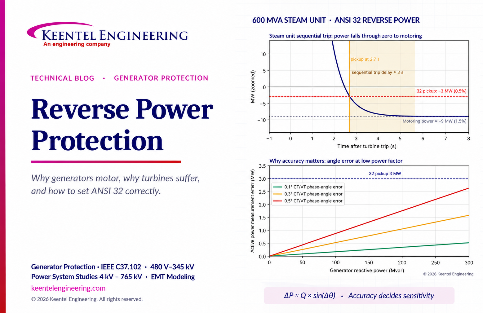
Learn reverse power protection (ANSI 32), generator motoring, relay pickup settings, time delays, sequential tripping and testing for US power plants.
Copy

By Team 2 Dexora
•
October 20, 2026
Explore grounding system testing with Keentel Engineering. Learn IEEE 80/81 methods, soil resistivity, ground resistance, and touch and step voltage safety.

By SANDIP R PATEL
•
October 13, 2026
Plan data center capacity with land screening, MW-per-acre estimates, grid power availability and interconnection feasibility studies from Keentel Engineering.

By SANDIP R PATEL
•
October 11, 2026
Learn which fault produces the highest current at a bus, why SLG faults can exceed three-phase faults, and how symmetrical components determine fault duty.

By SANDIP R PATEL
•
October 11, 2026
Learn why zero-sequence current pulsates in the dq0 frame, how Park's transformation works, and how inverter controls handle unbalance and ground faults.

By SANDIP R PATEL
•
October 11, 2026
Explore grid inertia, RoCoF and frequency response, with swing equation calculations, frequency nadir analysis and US power system simulation examples.

By SANDIP R PATEL
•
October 11, 2026
Learn transient stability analysis, swing equation, equal-area criterion and critical clearing time with a 345 kV worked example and NERC TPL-001 guidance.

By SANDIP R PATEL
•
October 11, 2026
Learn why inverter controls become unstable in weak grids, how PLL bandwidth and SCR affect stability, and how PSCAD EMT studies identify and mitigate oscillations.

By SANDIP R PATEL
•
October 11, 2026
Learn how STATCOMs improve voltage stability and prevent FIDVR. Explore reactive power sizing, delayed fault clearing, NERC criteria and 138 kV simulation results.





