
A Coordinated Electric System Interconnection Review—the utility’s deep-dive on technical and cost impacts of your project.
Challenge: Frequent false tripping using conventional electromechanical relays
Solution: SEL-487E integration with multi-terminal differential protection and dynamic inrush restraint
Result: 90% reduction in false trips, saving over $250,000 in downtime
ERCOT enforces all of the above through simulation, which means your model is your compliance case. The bar is now high:
- Whole-facility scope. The model must represent everything the IT load, the UPS and power conversion, the cooling plant, the protection and control systems in formats compatible with ERCOT's study platforms (PSS/E, PSCAD, TSAT).
- Real control loops, not approximations. Generic textbook representations are unacceptable. The model must capture the actual inner control behavior of your power electronics.
- Hardware-validated converter models. For electronic loads, the PSCAD model must be benchmarked against actual hardware testing including voltage ride-through and subsynchronous response. A model assembled from standard PSCAD library blocks fails by definition, because a generic block has never been tested against your vendor's hardware. The good news: validation is a hardware-type test, so results for a given converter product are reusable across every facility that uses it.
- Format migration. Facilities that previously submitted the older composite load model (CMLD) format must transition to EPRI's PERC1 format.
- Three checkpoints. Models are reviewed before the stability study begins (no model, no study), before each quarterly stability assessment, and for electronic loads one final time before energization, when you must submit as-built models with a documented comparison against the previously studied data and a sworn attestation that the model matches actual field settings. ERCOT's review takes 10 business days, extendable by 20 put it on your critical path.
- A living obligation. Change your technology, controls, or relay settings in a way that affects ride-through including converting a crypto mining site to an AI data center — and you've triggered a new interconnection study, even if your megawatts don't change.
| Parameter | Detail |
|---|---|
| System | 230 kV / 138 kV transmission corridors, wind and wet-snow icing exposure |
| Data basis | 15 years of minute-resolution forced-outage records + regional weather observations |
| Core methods | Event grouping, MVA performance curves, time-to-95%-restore, area outage rate curves, fragility modeling, rerun-history benefits, exceedance and log-domain risk metrics |
| Headline result | ≈85% of maximum resilience benefit at 60% of original capital; worst-event restoration window cut from 11 days to 5 in rerun-history terms |
| Decision supported | Capital portfolio selection; resilience plan filing; post-investment verification framework |
| System / Topic | Governing Standard(s) | What It Controls |
|---|---|---|
| Overall plant electrical distribution | IEEE 141 (Red Book); IEEE 666 | Distribution architecture, voltage selection, design of generating station auxiliary service systems |
| Power system studies | IEEE 399 (Brown Book); IEEE 551 | Load flow, symmetrical/asymmetrical short circuit, motor starting methodologies down to the lowest LV panelboard |
| Protection & coordination | IEEE 242 (Buff Book); IEEE 3004.5; IEEE C37 series | Generator relaying (21, 59N, 87G), time-current coordination, selective clearing between LV and MV tiers |
| GSU / UAT / SST transformers | IEEE C57.12.00 and C57 family | Transformer ratings, impedance, testing, loading |
| HV switchyard breakers | IEEE C37.06 | AC high-voltage circuit breaker preferred ratings |
| MV switchgear (13.8 kV) | IEEE C37.20.2; IEEE C37.20.7 | Metal-clad construction, compartmentalization, vacuum breakers; arc-resistant design with plenum venting |
| MV cable | UL 1072; ICEA S-93-639 (NEMA WC 74) | Type MV-105 shielded cable, 133% insulation level for HRG systems |
| LV switchgear (480 V) | IEEE C37.13; UL 1558 | Metal-enclosed LV power circuit breaker switchgear to 635 V, draw-out ACBs with electronic trip units |
| Motor control centers | UL 845; NEMA ICS 18 | LV-MCC construction, MCCB/MCP protection for motors under ~200 HP |
| Motors | NEMA MG-1 | Motor performance, starting characteristics, service factors |
| DC & battery systems | IEEE 485; IEEE 946 | Lead-acid battery sizing (125/250 VDC), DC auxiliary system design |
| Grounding | IEEE 80; IEEE 142 (Green Book) | Ground grid step/touch potential limits; system grounding including high-resistance grounding |
| Lightning protection | IEEE 998 | Direct-stroke shielding of switchyard and outdoor generator structures |
| Arc flash & electrical safety | IEEE 1584; NFPA 70E | Incident energy calculation; worker safety boundaries and PPE |
| Fire protection | NFPA 850 | Fire protection and risk management for combustion turbine generating plants |
| Installation code | NEC (NFPA 70); NESC | Wiring methods inside the plant fence; overhead/outdoor clearances at the switchyard |
| Interconnection & compliance | FERC LGIP; NERC MOD-025/026/027, PRC-019/024/029, FAC-008 | Interconnection process, model validation, protection/ride-through coordination, facility ratings |
| IFC / Construction Deliverable | Purpose |
|---|---|
| Stamped IFC packages | Legal basis for construction; P.E. responsible charge |
| Final relay settings & TCCs | Protection as-installed matches the coordination study |
| Calculation archive | Owner records; NERC audit evidence trail |
| Commissioning procedures | Safe, sequenced energization; MOD field testing |
| Construction support | RFIs, field changes, FAT/SAT witness |
| As-builts & model handoff | Operating baseline; future study currency |
| Metric | Outcome |
|---|---|
| Defects found pre-occupancy | Three topology defects and one settings-mismatch family corrected before load migration; the shared-switchboard defect alone would have invalidated the concurrently-maintainable claim on day one |
| IST findings | Fourteen additional discrepancies surfaced under scenario testing (control logic, alarm mapping, one generator sequencing fault) — all closed before handover instead of during operations |
| Black-building test | Passed on second execution; the first attempt exposed the generator sequencing fault under true block load, exactly the failure the compressed plan would never have found |
| Handover quality | Operations team certified on the actual failure scenarios; corrected EOPs and settings documentation delivered as controlled documents |
| Business outcome | Occupancy proceeded three weeks behind the original date — against an independent estimate that the uncorrected sequencing fault carried a high probability of a full facility outage within the first year |
Part 2 — Frequently Asked Questions: Large Load Interconnection
An electric grid must remain in continuous balance — generation onto the grid must equal consumption from it at every instant. PJM achieves this balance, and prices it, through a layered market architecture. Each layer operates on a different time horizon, and each one touches project economics differently.
| Domain | Key Standards / Codes | What They Govern |
|---|---|---|
| Fire safety | NFPA 855; UL 9540 / UL 9540A | Installation requirements, separation, gas management; system safety listing and thermal-runaway fire testing |
| Grid interconnection | IEEE 1547 (distribution); IEEE 2800 (transmission IBRs) | Ride-through, reactive capability, power quality, and performance at the point of interconnection |
| Power quality | IEEE 519 | Harmonic distortion limits at the PCC |
| Protection & grounding | IEEE 80 / 81 / 142; C37 series | Grounding system design and testing; protective relaying |
| Reliability compliance | NERC standards (incl. PRC ride-through requirements) | Registered-entity obligations for grid-connected storage |
Cable Testing Before Energization: The Twelve-Step Sequence, Rewritten as Engineering
Aug 16, 2026 | Blog
A Keentel Engineering Grid IQ technical guide for commissioning engineers, owner's engineers, EPC quality managers, and utility cable asset owners
Introduction: The Sequence Is Right. The Order and the Criteria Are Where Projects Fail.
There is a widely circulated infographic — you have almost certainly seen a version of it — laying out the cable testing sequence for HV, MV and AC cables before energization. Twelve numbered steps: visual inspection, continuity, insulation resistance, AC withstand, DC withstand where applicable, sheath integrity, phase identification, polarity, earth continuity, megger trending, final documentation, system readiness. The banner underneath reads: "Don't assume it's OK — test it before you energize."
That banner is correct and the twelve items are all real tests. As a reminder of scope, the list is useful.
As a sequence, it has three problems that cost real money:
The sheath test is in the wrong place. It sits at step 6, after the withstand tests. In practice the sheath test is the only after-installation test that finds pulling damage, rock in the trench bed, and tool strikes during joint-bay work — and it needs to happen before backfill, not after. Finding a jacket puncture at step 6 on a buried circuit means re-excavating.
Steps 4 and 5 are alternatives, not a sequence. You perform an AC withstand or a DC withstand, chosen by insulation type and cable age. Running both on the same extruded circuit is not thoroughness — a DC hipot on service-aged XLPE can create the defect it was meant to find.
The step that would actually catch the dominant defect is missing. Roughly three-quarters of failures on modern HV extruded cable systems occur in the accessories — the joints and terminations that are hand-built on site — and a simple pass/fail withstand test gives you no information about them unless they break during the test. Partial discharge measurement, or a monitored withstand, is what turns "this circuit survived" into "joint bay 4 has a defect."
This guide takes the twelve steps and rewrites them as engineering: the governing standard for each, the actual acceptance criterion, what the published failure data says about which tests are worth the money, and a corrected sequence.
Part 1 — What the Sequence Is Actually For
1.1 Withstand versus diagnostic — the distinction that determines everything
IEEE Std 400-2023, Guide for Field Testing and Evaluation of the Insulation of Shielded Power Cable Systems Rated 5 kV and Above, is the umbrella document for this whole subject. It catalogues the available field test methods, gives advantages and disadvantages for each, and — importantly — deliberately does not carry the detailed acceptance criteria, which live in the "point" documents: 400.1 (HVDC), 400.2 (VLF), 400.3 (partial discharge), 400.4 (damped AC).
The taxonomy it uses is the one that should shape your test specification:
- Withstand test — a go/no-go proof. The insulation either survives the applied voltage for the applied duration, or it does not. A pass tells you the circuit had no defect severe enough to break down under that specific stress. It tells you nothing about condition.
- Simple withstand — voltage applied, pass or fail, nothing recorded.
- Monitored withstand — voltage applied for the withstand duration while a diagnostic quantity (tan delta, partial discharge) is recorded. Same energization, same outage, pass/fail plus condition data.
- Diagnostic test — measures a property of the insulation (tan delta, PD, dielectric response) to estimate condition. No inherent pass/fail; interpretation is against criteria, baselines and trends.
If your commissioning specification calls for a simple withstand and nothing else, you have specified a test that answers one question — will it break today? — and declines to answer the more valuable one: where is the weak accessory?
The single most useful upgrade available to most cable commissioning specifications is to convert the withstand test to a monitored withstand. It costs one additional instrument connection and no additional outage time.
1.2 Where cables actually fail
Test effort should follow the failure data, and the failure data is unusually clear.
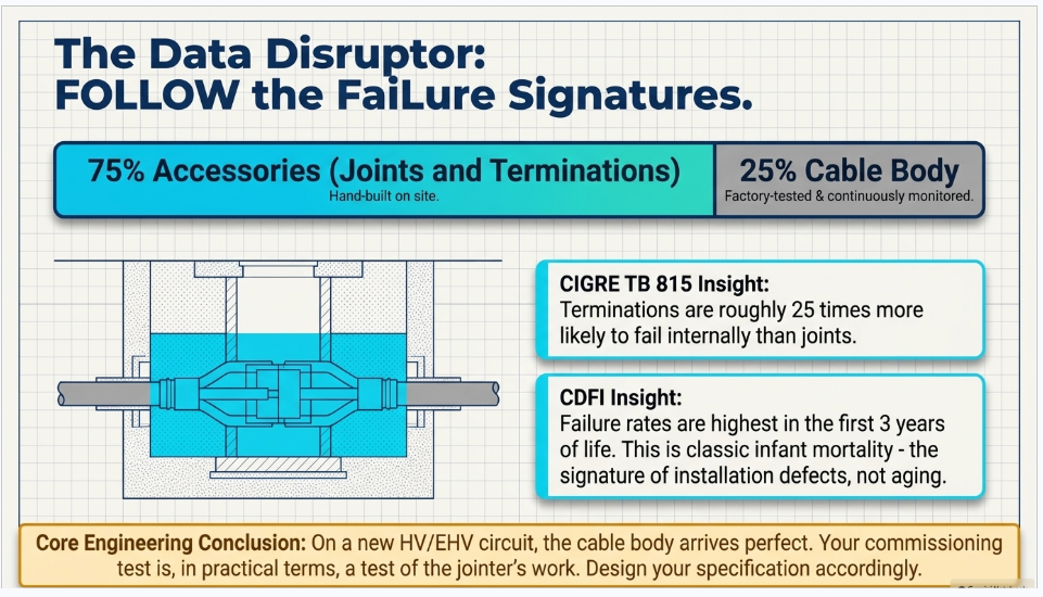
HV and EHV extruded systems — the accessories dominate. The EPRI/NEETRAC/DOE Cable Diagnostic Focused Initiative (CDFI), examining North American extruded cable systems installed since 2000, found accessories accounting for roughly 68–75% of failures, with the report's own summary noting "the propensity of the failure to occur in the accessories (3 to 4 times more frequently than the cable)." It also found that for those installations "the failure rate in the first three years of life is slightly higher than the failure rate after three years" — classic infant mortality, which is precisely the signature of installation defects rather than aging.
CIGRE's international survey confirms the direction. Technical Brochure 815 (WG B1.57, 2020), covering 2006–2015 across roughly 29,350 circuit-km of AC land cable, recorded 744 faults on land cable systems, split cable 56%, joints 16%, terminations 18%, other 9% — so accessories account for 34% of all faults, internal and external combined. Since external damage overwhelmingly strikes the cable body, the accessory share of
internal failures is considerably higher. The internal-cause rates make this explicit for 60–500 kV XLPE AC land cable:
| Component | Internal failure rate | Change vs the 2009 survey |
|---|---|---|
| Cable body | 0.069 per 100 km·yr | +30% |
| Joints | 0.002 per 100 units·yr | −40% |
| Terminations | 0.051 per 100 units·yr | +300% |
Per unit, a termination in that dataset is roughly 25 times more likely to fail internally than a joint. Overall cause split: internal 64%, external 29%, unknown 7%.
Medium voltage is a different picture. CDFI's North American MV surveys put the median utility failure rate at 3.5 failures per 100 miles per year (lower quartile 1.6, upper quartile 8, with a long right tail — use the median, not the mean, for any "typical utility" statement). The component split across all MV insulation types: cable 56.2%, splices 37.1%, terminations 5.6% — accessories at roughly 43%, with the balance between splices and terminations inverted relative to HV, which makes sense given the population of direct-buried repair splices.
The engineering conclusion. On a new HV or EHV circuit, the cable body arrives as an extruded, continuously monitored, factory-tested and factory-PD-tested product. The joints and terminations are built by hand, on site, often in a manhole or a trench, sometimes at night. Your commissioning test is, in practical terms, a test of the jointer's work. Design it accordingly.
Part 2 — The Twelve Steps, Rewritten
Step 1 — Visual inspection
Verify routing, glands, terminations, supports and identification tags; confirm no physical damage or improper installation.
The item worth adding is one that cannot be verified after the fact. Pulling tension, sidewall bearing pressure and bend radius are only verifiable while the pull is happening. Conductor stress limits of roughly 0.008 lb/cmil for soft copper and hard-drawn aluminium, sidewall pressure limits commonly 500 lb/ft for 600 V–15 kV non-shielded and 300 lb/ft for 25–35 kV cable, and minimum bending radii of 12× the shielded-conductor diameter or 7× the overall diameter — none of these leave a visible mark on an installed cable, and all of them produce a defect that surfaces years later.
A dynamometer chart from the pull, retained in the record, is evidence. A tick in a box after the cable is in the duct is not. If the specification does not require pull-tension recording, "visual inspection" cannot verify installation stress at all — and that is worth raising before the cable goes in the ground.
The second addition: photograph every accessory build. Semicon cut position, stress cone seating, interface preparation and shell closure are permanently invisible once the joint is closed. A photographic record of the build is the only evidence that will exist if the joint fails in year three.
Step 2 — Continuity test
Confirm conductor continuity end to end; detect open circuits or incorrect connections.
Continuity is a floor, not a test. Three upgrades convert this step from a formality into useful data:
Conductor DC resistance against a standard. IEC 60228:2023 (Edition 4.0) gives maximum DC resistance at 20 °C by nominal cross-section and conductor class. Measure with a micro-ohmmeter — 100 A or more on HV conductors — correct to 20 °C, and compare. A significant deviation from the IEC 60228 value points at a bad compression joint or the wrong conductor size, and it is the only test in the sequence that would catch either.
TDR as a commissioning fingerprint. Fire a fast low-voltage pulse into the conductor-to-screen transmission line and record the reflectogram. Every impedance discontinuity — each joint, each termination, the far-end open — produces a signature. Distance is d = v·t/2, where the velocity of propagation for XLPE is typically around 0.5–0.58 c (take it from the cable datasheet; VOP is the largest single error source in TDR distance).
Why it belongs in a commissioning scope: it is a free, non-destructive as-built record. It proves circuit length, proves the number and position of joints matches the as-built drawing, and becomes the reference trace against which any future fault-location TDR is differenced. A fault trace read against a commissioning baseline is dramatically easier to interpret than one read cold, at 3 a.m., with the circuit out. Very few US commissioning specifications require it. Adding it costs an hour.
Cross-check against the as-built joint schedule. If the TDR shows four reflections and the drawing shows three joints, somebody added a joint. That is worth knowing before energization, not after.
Step 3 — Insulation resistance test
Measure insulation resistance between conductors and earth using a megger; ensure insulation integrity before energization.
This step is genuinely necessary and almost universally over-interpreted.
What IR does well
It detects gross problems — a conductor shorted to screen, a flooded or heavily contaminated termination, an omitted insulation step, moisture in an accessory, a conductive path across a stress cone surface. It is fast and cheap. And it performs one function nobody puts in the specification but everyone relies on: it protects the expensive test set from being connected to a dead short.
What IR does not do — and this is the part that gets misrepresented:
- It cannot detect water trees, the dominant aging mechanism in extruded MV cable. Water trees are AC-field-driven, partially conductive structures. At 5 kV DC they present essentially infinite resistance.
- It cannot detect voids, delaminations or PD sites. A void is a capacitive defect. It passes no DC.
- It cannot detect a defective accessory interface that will discharge at 1.3 U₀.
- It says very little about remaining life. A cable that will fail next month typically meggers as infinity.
Are PI and DAR meaningful on cable? Largely no
Polarization Index (10 minutes ÷ 1 minute) and Dielectric Absorption Ratio (60 s ÷ 30 s) measure dielectric absorption — the slow polarization current of a multi-layer, hygroscopic insulation system. They were developed for, and are defined in, IEEE Std 43 for rotating machine windings, where mica-and-resin tape systems produce a large absorption current. A homogeneous extruded polyethylene dielectric has very little absorption current: the charging transient is dominated by geometric capacitance and settles quickly, so PI on healthy XLPE tends toward 1 and carries essentially no diagnostic content.
On PILC — a genuine laminated, oil-paper, moisture-sensitive system — absorption-based ratios retain real meaning, and IEEE 400.1's DC test evaluation is built on exactly that current-versus-time physics.
Working rule: PI and DAR are meaningful on machines and on PILC, and close to meaningless on extruded cable. Specifying a PI acceptance criterion for an XLPE feeder is a requirement nobody can fail and nobody learns anything from.
Step 4 — AC withstand (hi-pot) test
Apply specified AC test voltage to verify dielectric strength; detect hidden insulation defects before service.
AC is technically the right stress — it excites the same failure mechanisms the cable will see in service, unlike DC. The problem is arithmetic.
Cable is a distributed capacitor. Charging current and the reactive burden on the source are:
I_c = 2πfCV and Q = 2πfCV²
Work that through:
| Case | Capacitance | Test voltage | Frequency | Charging current | Reactive power per phase |
|---|---|---|---|---|---|
| 15 kV XLPE, 1 km (C ≈ 0.25 µF/km) | 0.25 µF | 21 kV | 60 Hz | 2.0 A | 42 kVA |
| 15 kV XLPE, 5 km | 1.25 µF | 21 kV | 60 Hz | 9.9 A | 208 kVA |
| 138 kV XLPE, 5 km (C ≈ 0.20 µF/km) | 1.0 µF | 136 kV | 60 Hz | 51 A | 7.0 MVA |
| 400 kV XLPE, 10 km (C ≈ 0.25 µF/km) | 2.5 µF | 276 kV | 60 Hz | 260 A | 72 MVA |
| 15 kV XLPE, 1 km | 0.25 µF | 21 kV | 0.1 Hz | 3.3 mA | 69 VA |
(Capacitance values are typical; state the assumed value in any project calculation.)
A 72 MVA, 276 kV power-frequency test transformer is not a transportable object. That is why nobody 60-Hz-hipots EHV cable, and why a conventional 50/60 Hz set can test roughly 50 feet of 15 kV cable where a VLF set handles a couple of miles.
Series resonant test systems solve this. A variable-frequency converter feeds an exciter transformer and a fixed HV reactor in series with the cable capacitance. The converter sweeps frequency until X_L = X_C, at f_res = 1/(2π√(LC)). At resonance the reactive power circulates between reactor and cable, and the supply only makes up the losses — so the required source rating is roughly Q_test divided by the circuit quality factor, typically 50–100 for modern reactors. The 72 MVA EHV case becomes a feed of roughly 0.7–1.4 MW, and a transportable one.
The accepted band is 20–300 Hz, which appears explicitly in IEC 60502-2's after-installation AC option and in ANSI/NETA ATS-2025 Table 100.6.5, "Shielded Power Cables, AC (20 Hz–300 Hz) Test Voltages" — near-power-frequency resonant AC is now a first-class tabulated acceptance method in a US standard, not an exotic alternative.
After-installation AC test values. The IEC voltage hierarchy is:
| Standard | Current edition | Voltage range |
|---|---|---|
| IEC 60502-2 | Ed. 3.0:2014 + AMD1:2024 | 6 kV to 30 kV (U_m 7.2–36 kV) |
| IEC 60840 | Ed. 5.0:2020, consolidated Ed. 5.1:2023 | above 30 kV to 150 kV (U_m 36–170 kV) |
| IEC 62067 | Ed. 3.0:2022 | above 150 kV to 500 kV (U_m 170–550 kV) |
IEC 60502-2 offers four alternative after-installation tests for 6–30 kV cable:
- DC at 4 U₀ for 15 minutes — new cables only
- AC at rated phase-to-phase voltage U for 15 minutes, at 20–300 Hz
- AC at U₀ for 24 hours at power frequency — the "soak test"
- VLF at 3 U₀ for 15 minutes at 0.1 Hz
For HV extruded cable, CIGRE Technical Brochure 841 (WG B1.38, 2021) recommends a commissioning test of 1.7 U₀ for 60 minutes at near power frequency for AC XLPE/EPR cables in the 220–400 kV range, with a 1.0 U₀ soak for 24 hours as the recognized alternative where a resonant set cannot be mobilized. The per-U_m values live in IEC 60840 and IEC 62067 Clause 16.3, Table 12 — get them from the standard rather than from a vendor summary, because the published summaries conflict on whether the multiplier is flat at 1.7 U₀ or descends with voltage class.
Two practical notes
First, a soak test at U₀ for 24 hours proves far less than an over-voltage test — it applies no more stress than normal service. It is a legitimate fallback, not an equivalent. Second, an AC withstand with PD monitoring is worth several times an AC withstand alone, for reasons Part 3 makes quantitative.
Step 5 — DC withstand (where applicable)
Verify insulation performance under DC test voltage according to project specifications and cable type.
The parenthetical "where applicable" is doing an enormous amount of work, and it deserves unpacking, because this is the most misunderstood test in the sequence.
Where DC is correct:
Laminated dielectric cable — PILC, pipe-type, pressurized. This is the entire premise of IEEE Std 400.1-2018, whose title states the restriction explicitly: Guide for Field Testing of Laminated Dielectric, Shielded AC Power Cable Systems Rated 5 kV to 500 kV Using High Voltage Direct Current. Oil-impregnated paper does not trap space charge the way crosslinked polyethylene does, and the field distribution in a laminated dielectric under DC is resistive and stable. DC is the appropriate proof medium here, and the current-versus-time behaviour is genuinely diagnostic.
The jacket or oversheath integrity test
— see Step 6. The jacket is a thin unshielded polymer barrier with no water-tree population and no service AC stress, so the space-charge objection does not apply.
Low-voltage insulation resistance at 2.5–5 kV DC, which is safe on all cable types.
Where DC is wrong, and why:
On extruded insulation — XLPE, TR-XLPE, EPR — DC withstand is contraindicated for two documented mechanisms. The US NRC's technical review DC HiPot Testing of Aged XLPE-Insulated Cables is the most useful primary-source summary of the underlying literature:
Space charge. DC field application injects and traps charge carriers in the polymer. Work by Hozumi and colleagues showed DC-treated polyethylene retaining more trapped charge than untreated specimens after equal aging, with charge levels increasing further during subsequent AC aging; Takeda and colleagues identified the mechanism in XLPE as dissociation of impurities — antioxidants and acetophenone crosslinking byproducts — producing hetero space charge attracted to the electrodes. When the cable is re-energized on AC, the trapped charge does not redistribute at 60 Hz. It superimposes on the AC field and produces local stress enhancement above design stress. Dissipation can take up to 24 hours.
Water tree to electrical tree conversion. The EPRI-sponsored Detroit Edison study is the canonical experiment. Aged cable segments that received a DC hipot consistently failed before non-DC-tested aged segments when returned to accelerated water-treeing conditions — the result summarized as "the dc tested aged cable segment always failed before the non-dc tested previously aged cable segment," with 100% consistency and, in the investigator's words, "no statistical analysis required."
The accurate framing, which matters for writing a defensible specification: DC hipot is not banned. It is contraindicated for service-aged extruded insulation, where it can create the defect it was meant to find. And it is uninformative everywhere on extruded cable, because DC does not excite the AC failure mechanisms. Notably, the same EPRI work found that DC testing prior to aging did not appear to influence cable life — which is why several owner specifications still permit DC hipot on new extruded cable at commissioning while explicitly prohibiting it for maintenance testing of aged cable.
CDFI's own verdict on DC withstand for extruded circuits is blunt: "no evidence that it provides significant benefits for extruded cable circuits", and it "can cause premature failures in aged, XLPE insulated cables."
Steps 4 and 5 are therefore a decision, not a sequence. The decision tree:
| Cable type and age | Appropriate withstand method |
|---|---|
| New extruded, MV | VLF (monitored, with tan delta and/or PD) or 20–300 Hz resonant AC |
| New extruded, HV/EHV | Resonant AC at near power frequency, with PD monitoring |
| Service-aged extruded | VLF or damped AC with diagnostics. Not DC. |
| Laminated dielectric (PILC, pipe-type) | DC per IEEE 400.1 |
| Any oversheath / jacket | DC per IEC 60229 — see Step 6 |
Step 6 — Sheath integrity test
Check the cable outer sheath for damage or moisture ingress; confirm proper sheath continuity.
This is the most undervalued test in the sequence and the one most often performed too late.
The number. IEC 60229:2007 (Edition 3.0), Electric cables — Tests on extruded oversheaths with a special protective function, Clause 5, specifies the after-installation test as:
4 kV DC per mm of specified nominal oversheath thickness, capped at 10 kV, applied for 1 minute, with no breakdown.
The metallic layer is driven negative with respect to earth — deliberately, so the test is cathodic rather than corrosive, matching the polarity of the factory routine test.
This resolves a long-running confusion. The "10 kV DC for one minute" that everyone quotes is the ceiling of a thickness-proportional rule, not a flat value. A 2.5 mm HDPE oversheath hits the cap exactly (4 × 2.5 = 10 kV). A thinner MV jacket gets proportionally less, and applying 10 kV to it is an over-test. The competing "5 kV" figure that also circulates comes from a different lineage — German VDE practice gives 3 kV for PVC sheath and 5 kV for PE sheath; UK manufacturer practice per the BS 6622 / BS 7835 families gives 8 kV and 5 kV respectively for one minute.
For context, the same standard's factory routine test is 8 kV/mm capped at 25 kV for 1 minute, and the post-abrasion type test is a flat 20 kV — so the after-installation value is deliberately the gentlest of the three.
Leakage current is the real acceptance criterion in practice. The pass/fail is "no breakdown," but a rising or step-changing leakage current is the actionable signal — values moving from the microampere range into milliamperes indicate jacket damage even without a flashover. Test-set manufacturers publish permitted leakage bands that scale with route length, and a 10-minute duration is common practice for QA-grade sheath testing rather than the standard's 1 minute.
Why it matters — three reasons, in order of severity:
1. It is the water ingress path. A punctured oversheath admits moisture to the metallic screen, and from there longitudinally under the screen to the insulation screen and the insulation itself. On extruded cable that is the front end of the water-treeing mechanism: a jacket defect at commissioning becomes an insulation failure in year eight. On lead-sheathed cable it is also a corrosion initiation site, since the jacket is the only barrier between the sheath and the soil.
2. It is the only after-installation test that finds installation damage. Sidewall pressure damage, sharp bends, rock in the bedding, tool strikes during joint-bay backfill — none of these appear on the conductor insulation test, and all of them appear on the sheath test. Which is why it belongs before backfill, not at step 6. Testing before backfilling is the difference between a repair and an excavation.
3. On HV systems it is the only test that proves the bonding scheme is what the drawings say. This one deserves its own section.
Locating a sheath fault. Two techniques, used together:
- Pre-location by Murray loop bridge — the faulted screen and a healthy screen or phase form a resistance ratio arm, shorted together at the far end and nulled from the near end. Works for low- and high-resistance faults over kilometre-scale routes. Its accuracy degrades if the two screens differ in specific resistance.
- Pin-pointing by step voltage (A-frame) — pulsed DC of defined polarity is fed into the faulty screen; the return current through the soil creates a surface voltage gradient. The operator walks the route with two earth spikes roughly 0.8 m apart. The deflection direction points toward the fault, the reading peaks directly over it and reverses polarity past it. Accuracy is quoted in centimetres, and the polarity reversal is what distinguishes the real fault from a secondary defect.
Bridge to get within tens of metres, A-frame to get to the trowel.
Step 6b — The section the checklist omits: sheath bonding and link boxes
On any single-core HV circuit, current in the core induces a longitudinal EMF in the parallel metallic sheath. You can either let that EMF drive a circulating current — and lose ampacity to sheath I²R loss — or block the current and accept a standing voltage on the sheath. The three schemes:
- Both-end (solid) bonding. Sheath earthed at both ends. Standing sheath voltage near zero, no sheath voltage limiters needed, safest to touch — but a closed loop exists, circulating sheath currents flow, and the resulting losses can derate the circuit substantially. Used on short circuits where the ampacity penalty is affordable.
- Single-point bonding. Sheath earthed at one end only; the other end open through a link box. No circulating current, no sheath loss, maximum ampacity. The penalty is a standing induced voltage at the open end, proportional to circuit length and load current — which is what limits minor-section length, since the standing voltage must stay under the project's touch-voltage limit while the sheath insulation and the SVLs survive far larger transients during through-faults and surges. A parallel earth continuity conductor is normally laid alongside.
- Cross-bonding. The route is split into groups of three equal minor sections, with the sheaths transposed at each of the two intermediate joint bays so that each sheath sees, in turn, the induced EMF of each phase. Over a full major section the three EMFs sum to approximately zero — no circulating current and no large standing voltage. The cost is complexity: sectionalized joints, a cross-bonding link box at each transposition, and degraded cancellation if section lengths are unbalanced.
Here is why the sheath test matters so much on these systems. In a single-point-bonded or cross-bonded circuit, the sheath is deliberately held off earth for the length of a minor section. A sheath-to-earth fault silently converts a single-point-bonded section into a solidly bonded one. Nothing trips. The circuit simply begins circulating sheath current, loses ampacity, and runs hotter than design for the rest of its life. On a cross-bonded system, one jacket fault also unbalances the transposition, so the vector cancellation stops working.
The sheath test is the only commissioning test that detects this. Nothing in the conductor test sequence will.
Sheath voltage limiters are metal-oxide surge arresters rated for the sheath's much lower continuous voltage — typically 0.8 to 4.8 kV MCOV for link-box mounted units, 4 to 14 kV outdoors, with selection driven by a project-specific insulation coordination study. Their real-world failure modes are worth knowing: thermal runaway from undersizing, moisture ingress into a flooded buried link box (the dominant killer), failure to earth (which again silently converts single-point to solid bonding), and loose or corroded link-box connections.
Commissioning scope for link boxes, per current CIGRE guidance, typically includes: verifying enclosure and gland sealing against a submerged duty if the chamber floods; auditing every link position against the bonding drawing (this is where cross-bonding transpositions get built wrong, and it is nearly impossible to detect later without dismantling); torque checks on all bolted connections; insulation resistance on each SVL, disconnected, as a baseline; continuity and resistance of bonding leads and the earth continuity conductor; and phase identification of the coaxial bonding leads, which are a classic mislabelling point. Photograph the interior before closing.
One procedural note that catches people: the sheath test must be performed with the SVLs temporarily disconnected, or they will conduct at 10 kV and mask the jacket entirely.
Two currency flags for anyone writing a specification. IEEE Std 575-2014, the guide for bonding shields and sheaths of single-conductor cables, moved to Inactive-Reserved on 27 March 2025, with a revision project active and retitled to emphasize induced voltage and current calculation. IEEE Std 400.4-2015 (damped AC) moved to Inactive-Reserved on 26 March 2026, also with an active revision. Neither method is withdrawn — the documents are in reserve — but a specification citing them by year is now citing reserved standards. CIGRE TB 797 (2020) is the current reference for bonding system design, testing and maintenance at 66 kV and above.
Step 7 — Phase identification
Verify correct phase sequence and cable identification; prevent incorrect equipment connections.
Three distinct checks get collapsed into this one line, and they happen at different times with different equipment:
Phase identification (de-energized). Confirms which conductor at end A is which at end B. The standard method: ground one phase at the remote end, leave the others floating, and measure from the near end with the insulation tester at 1 kV DC. The grounded phase reads near zero; the others read in the gigaohm range. Repeat per phase. The trap: all remote conductors must be lifted from ground first. If they are not, every phase reads continuous and the test is worthless. Station a safety watch at the remote end.
Phasing check (energized). Confirms two sources or sections are in phase before paralleling — a live phasing set or voltmeter across the open point reads near zero between corresponding phases and full phase-to-phase voltage between non-corresponding ones.
Phase sequence / rotation (energized). Confirms A-B-C versus A-C-B at the switchgear with a rotation meter, on the primary or via VT secondaries.
Why it matters: closing onto an out-of-phase source produces a fault of up to twice normal magnitude through a transformer or generator, with mechanical damage to windings and possible destruction of the machine. Downstream, motors run backwards and every directional and differential protection element is mis-polarized. The acceptance criterion is unambiguous and worth writing down: each phase identified consistently at both ends, sequence matching the approved single-line, no ambiguity anywhere in the record.
Step 8 — Polarity test
Confirm correct polarity, especially for DC systems and control cables.
Verify positive and negative continuity end to end on station battery and DC distribution feeders, and on all control, CT and VT secondary, and trip circuits, before energization.
Two specific hazards justify the step. Reversed polarity into a charger, inverter or polarized load is immediately destructive. And polarity errors on CT secondaries invert differential and directional protection — producing a relay that behaves perfectly under secondary injection and trips backwards on a real fault. Confirm CT polarity by DC flick test: momentary DC into P1–P2, deflection direction observed at S1–S2. Nothing else proves it as installed.
Step 9 — Earth continuity test
Verify the continuity of protective earthing conductors; ensure a low-resistance grounding path.
For the cable system specifically, this means proving the metallic screen or concentric neutral is continuous end to end and correctly bonded at the intended point or points. Measure screen resistance with a micro-ohmmeter and compare against the calculated value for the screen cross-section and route length.
On single-point-bonded and cross-bonded HV systems this is emphatically not a simple continuity check. The screen is intentionally discontinuous at sectionalized joints. The test must follow the bonding diagram section by section, with link boxes configured, and the acceptance criterion is that the measured configuration matches the design — not that everything reads continuous. A test technician who "fixes" a discontinuity they were not expecting has just destroyed the bonding scheme.
Step 10 — Megger trending
Compare insulation resistance values with previous records; identify insulation deterioration over time.
The intent is right — baselines and trends beat single readings — but insulation resistance is close to the worst quantity on a cable to trend, for four reasons:
1. The measurement is dominated by the terminations, not the cable. Surface leakage across two stress cones in a humid switchroom swamps the volumetric leakage of a kilometre of XLPE. Two readings a year apart largely record the weather and how recently somebody wiped the terminations.
2. The reading sits near the top of the instrument's useful range. Expected values for XLPE are quoted at above 10,000 MΩ·km at 20 °C. You are trending noise against the instrument ceiling.
3. Temperature sensitivity is brutal. Insulation resistance is roughly exponential in temperature — the working rule is a halving of IR per 10 °C rise. The same XLPE quoted at above 10,000 MΩ·km at 20 °C falls to roughly 10 MΩ·km at 90 °C: a thousand-to-one range. Without accurate insulation temperature — not ambient; cable core temperature, which lags by hours — and correction to a common base, a year-over-year trend is meaningless.
4. Length must be normalized. In MΩ·km or MΩ per 1,000 ft, or a 500 m circuit and a 3 km circuit are incomparable.
What to trend instead. If the objective is genuinely to track condition over the asset's life, the quantities worth baselining at commissioning and repeating are:
- Tan delta at U₀ and its tip-up (VLF-TD and VLF-DTD), on MV extruded cable
- Partial discharge inception and extinction voltages relative to U₀, and the location of any detected source
- The TDR reflectogram, as a physical fingerprint of the circuit
- Conductor and screen resistance, temperature-corrected
- Sheath leakage current at the standard test voltage
Every one of those has more diagnostic content than an IR reading, and all of them are obtainable during commissioning at marginal additional cost.
Step 11 — Final documentation
Record all inspection and test results; ensure compliance with project specifications before energization.
The commissioning record for a cable circuit is not a completion artifact. It is the baseline for the asset's entire diagnostic life, and it has to be built that way from the start.
A defensible cable test record contains, per test:
- The instrument, its serial number, and its calibration certificate date — dated before the test
- Test date, ambient conditions, and where obtainable, cable temperature
- Technician name and certification level
- The acceptance criterion applied and its source standard and edition
- Measured values, in normalized units where applicable
- The comparison baseline, where the criterion is comparative
- Disposition
Plus, for the circuit as a whole: the TDR baseline trace, the as-built joint and termination schedule with positions, the bonding diagram with as-built link configurations, the accessory build photographs, the pull-tension record, and the sheath test result with the pre-backfill date on it.
A record that says "pass" is not re-evaluable. A record that says "measured 0.0032 tan δ at U₀; criterion per IEEE 400.2-2024 PE-based insulation, No Action Required below 4×10⁻³; instrument SN 12345, calibrated 14 months prior" can be defended, audited and trended for thirty years.
Step 12 — System readiness
Confirm all test results are acceptable; remove temporary test connections and issue clearance for energization.
Two items here are worth elevating from housekeeping to formal hold points:
Removal of temporary connections and grounds. Temporary safety grounds left on, shorting screws left in CT circuits, test leads left connected to a link box — each of these produces an energization event rather than an energization. Make it a signed checklist against a numbered register of every temporary connection installed, not a walk-around.
Restoration of the bonding configuration. Every link box opened for testing must be restored to the design configuration and re-verified against the bonding drawing before energization. SVLs disconnected for the sheath test must be reconnected. This is the single most likely way for a correctly designed and correctly tested bonding scheme to be energized wrong.
Part 3 — The Step That's Missing: Partial Discharge
If the failure data says accessories cause three-quarters of HV failures, and a simple withstand test cannot see an accessory defect unless it breaks, then the sequence needs a test that can. That test is partial discharge measurement — and the data on it is unusually good.
3.1 What PD is measured against
IEEE Std 400.3-2022 governs field PD diagnostic testing of installed shielded cable systems — cable, joints and terminations, online and offline. Note the retitle from the 2006 edition ("…in a Field Environment" → "Field Diagnostic Testing"): it signals the shift from PD as a pass/fail gate to PD as a diagnostic and localization tool. IEC 60270 defines apparent charge in picocoulombs and the calibration procedure that makes a pC number mean anything. IEC 60885-3 covers the factory method on extruded cable lengths.
3.2 Why there is rarely a universal on-site pC limit
This is worth understanding, because specifications that demand one are unenforceable:
Calibration breaks down on an installed system. IEC 60270 calibration injects a known charge at the terminals. On an installed circuit the PD source may be a kilometre away, and attenuation and dispersion of the PD pulse along the cable mean the charge measured at the terminal is not the charge at the defect — with a length- and frequency-dependent relationship between them. A 50 pC reading from a termination and a 50 pC reading from a joint 2 km out are completely different physical defects.
Online measurement cannot legitimately report pC at all, because the coupling path is uncalibrated. Online PD is inherently comparative and trended, not absolute.
Site noise floor is variable and often dominant — achievable sensitivity is set by the substation environment, not by the instrument.
And the meaningful quantity is inception voltage relative to service stress, not magnitude. A discharge that initiates at 1.7–2.0 U₀ and extinguishes at 1.5 U₀ is a different risk from a small discharge that never extinguishes above 1.0 U₀ — the second one is active every day in service.
The factory number people mistakenly carry into the field is IEC 60502-2's routine test: raise to 2 U₀, hold 10 seconds, reduce to 1.73 U₀, with no detectable discharge above a declared sensitivity of 10 pC for routine tests or 5 pC for type tests. That is a number obtained on a drum, in a screened room, on a calibrated circuit. It does not transfer.
A commissioning specification that is actually enforceable requires: (a) a documented sensitivity and noise-floor check at the start of the test; (b) no detectable PD above the demonstrated sensitivity at and below a stated multiple of U₀; (c) PD inception voltage at or above a stated multiple of U₀; (d) localization of any detected source to a specific accessory; and (e) raw data archived as the baseline for future trending. "≤5 pC" is not enforceable. That list is.
3.3 The data on when PD appears and how long to hold
CDFI's HV and EHV work measured the distribution of PD inception voltages and onset times directly, and the numbers make the case for the test duration on their own:
| Applied voltage | Cumulative share of cases showing PD |
|---|---|
| U₀ | 1.4% |
| 1.4 U₀ | 11.4% |
| 1.7 U₀ | 54% |
And at 1.7 U₀, approximately 92% of PD sites were detected within 60 minutes — which is why CDFI recommends at least 30 minutes at 1.7 U₀, with 60 minutes preferred to capture the remaining 8%.
Read those two findings together and the point is stark: at operating voltage, PD is detectable in fewer than 2% of cases. At 1.7 U₀, it is detectable in more than half. A soak test at U₀ — the fallback option in several specifications — will find almost nothing.
3.4 The defect mechanisms PD actually finds
All of them are workmanship, and all of them are invisible once the joint is closed: semiconductive layer not fully removed or over-cut into the insulation; contaminated or incorrectly lubricated interfaces; incorrect stress cone or deflector positioning; insufficient interface pressure; voids in field-poured resin; moisture in a joint shell; wrong assembly dimensions; missing or misapplied field-distribution elements.
The consequence for test design: the method must be able to localize, not merely detect. A single-ended time-domain measurement with reflection mapping, or a double-ended or distributed measurement, is what turns "this circuit has PD" into "excavate joint bay 4." IEEE 400.3-2022 gives guidance on when each is appropriate.
Part 4 — What the Evidence Says About Whether Any of This Works
This is the part most cable-testing content avoids, and it is the part an owner should care most about. The Cable Diagnostic Focused Initiative — an EPRI, NEETRAC and US DOE program under DOE award DE-FC02-04CH11237, final Phase 1 report December 2010, with Phase II chapters following — remains the largest independent evaluation of cable diagnostics ever published, covering roughly 10,824 conductor miles across all techniques.
4.1 The headline conclusions, in CDFI's own words
"Diagnostic tests can work. They often show many useful things about the condition of a cable circuit, but not everything desired."
"Most diagnostic technologies examined do a good job of accurately establishing that a cable circuit is 'good'. They are not as good at establishing which circuits are 'bad'."
"No one diagnostic is likely to provide sufficient information to accurately establish the condition of a cable circuit."
"Diagnostics are generally unable to determine definitively the longevity of the circuit under test."
That second quote is the one to internalize. A cable diagnostic is a good negative test and a mediocre positive one. Passing tells you a great deal. Failing tells you less than the marketing suggests. This is why CDFI advocates combining features rather than relying on a single method, and why a monitored withstand — which gives you a withstand result and diagnostic data from one energization — is such good value.
4.2 Simple withstand: how well does it actually perform?
CDFI Chapter 9 evaluated 7,875 miles tested between 2001 and 2008 across XLPE, paper and EPR:
- Accuracy: raw median 93.0%, weighted median 87% of tested cable did not fail within two years of the test.
- Failure-on-test rates at IEEE 400.2 recommended voltages: roughly 2.0% at 15 minutes, 2.7% at 30 minutes, 3.7% at 60 minutes.
That second row is the argument for duration, and CDFI states the consequence directly: "Ten failures representing more than 230 conductor miles would have gone undetected if the test had been terminated at 15 min." Nearly half of the defects a 60-minute test finds are invisible at 15 minutes. If your specification says 15 minutes because that is what fits the outage window, you are buying roughly half the test.
There is also a finding that reframes what "failing on test" means. CDFI found the likelihood of subsequent failure notably lower for sections that failed in a controlled manner during the test and were then repaired than for sections that passed. That is not a paradox — it is selection. A test failure identifies and removes a defect; a test pass leaves whatever was below threshold in the ground. (CDFI's own chapter contains internally inconsistent figures on the magnitude of this effect, drawn from different datasets with small samples, so treat the direction as robust and the magnitude as unsettled.)
4.3 Does a diagnostic program pay?
CDFI's benefits chapter gives two field cases:
- Case A — utility VLF withstand program, four years: 9 outages with diagnostics versus 19 without, a 53% reduction. Note the nuance, because it is the honest part: total failures were higher with diagnostics (32 versus 19), because defects were being caught on test rather than in service. The program did not reduce the number of defects; it changed where and when they surfaced — from an unplanned outage to a controlled test.
- Case B — service-provider PD program, ten years: 13 versus 19 outages, a 32% reduction.
- Economic outcome for Case A: roughly $350,000 benefit, four to five times the cost of the program. For HV/EHV commissioning testing, CDFI puts the benefit between $1.3 and $2.6 million over a fifteen-year horizon.
And a conclusion that belongs in every business case: "Intangible costs are decisive. Without them Diagnostic Programs are not beneficial." If your economic model counts only crew time and replacement cable, and not the cost of an unplanned outage to the customer, the program will not justify itself on paper — regardless of whether it is worth doing.
4.4 How often does a new circuit fail its commissioning test?
Published figures exist but need careful handling. CIGRE's Science & Engineering journal reports that "12% of all on-site acceptance tests on newly installed circuits resulted in breakdowns, mostly in cable joints and terminations" — attributed within that paper to a further reference, which is worth chasing before you rely on it. The same source reports that 40% of surveyed practitioners had observed an insulation breakdown during testing, and that in more than 70% of those cases PD was detected before breakdown — which is, again, the argument for monitoring during the withstand rather than simply applying it.
CIGRE TB 841 compares non-pass rates for terminations and joints between near-power-frequency and damped AC commissioning tests, drawing on a test-experience database spanning 1997 to end-2016. The actual percentages are in the brochure. If commissioning failure rates matter to your business case, that is the document to buy.
A directional figure worth stating carefully: a large commercial PD-testing database covering more than 250,000 field tests across 17 countries reports roughly 37% of systems at 5–500 kV having at least one substandard component, rising to about 45% for HV and EHV, with terminations defective in about 14% of HV/EHV cases. Those are vendor-published figures from a firm selling the test, and the headline before/after comparisons in that
dataset compare non-randomized populations of very different sizes — but the component-level defect percentages are consistent with CDFI and CIGRE, and are worth knowing.
Part 5 — Tan Delta Criteria: The Trap Nobody Warns You About
Tan delta is the most useful single diagnostic in MV cable commissioning and the easiest to apply wrongly. Three parameters, all expressed in units of 10⁻³:
- Mean VLF-TD — mean tan δ at U₀; the absolute loss level
- VLF-TDTS — temporal stability; the standard deviation of readings over time at fixed voltage (the 2024 edition recommends computing at both 1.0 U₀ and 0.5 U₀)
- VLF-DTD — differential tan delta, or tip-up: TD at 1.5 U₀ minus TD at 0.5 U₀
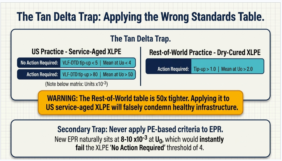
The trap: IEEE 400.2 does not publish one table. It publishes a family, split by insulation type and by geography — and the numbers differ by more than an order of magnitude between them. US service-aged XLPE has historically run far higher tan δ than European and Asian dry-cured XLPE, so the criteria diverge.
For PE-based insulations (PE, XLPE, TR-XLPE) under the criteria applicable to US practice:
| Condition | VLF-TDTS (std dev), ×10⁻³ | VLF-DTD tip-up, ×10⁻³ | Mean VLF-TD at U₀, ×10⁻³ |
|---|---|---|---|
| No Action Required | < 0.1 | < 5 | < 4 |
| Further Study Advised | 0.1 – 0.5 | 5 – 80 | 4 – 50 |
| Action Required | > 0.5 | > 80 | > 50 |
The equivalent "rest of world" table for the same insulation sets Action Required at tip-up above 1.0 and mean above 2.0 — figures roughly fifty times tighter. If a client specification or a vendor report shows numbers around 1–2 ×10⁻³ as the boundary for "good XLPE," it is on the other table. Applying it to US service-aged cable will condemn a great deal of healthy plant.
Two further cautions:
Do not apply XLPE criteria to EPR. New EPR typically sits in the 8–10 ×10⁻³ range at U₀, against under 1 ×10⁻³ for new XLPE. The XLPE "Action Required" threshold of 50 would be comfortably passed by healthy EPR, but the "No Action Required" threshold of 4 would condemn every EPR cable ever made. ANSI/NETA ATS-2025 Table 100.6.7.2 is now the accessible published source for EPR evaluation criteria in US practice, alongside Table 100.6.7.1 for PE-based insulations.
Do not apply aged-cable criteria to a new cable. IEEE 400.2 itself carries the caveat that for newly installed cable
"insufficient data have been collected to make precise estimates of criteria, consequently the criteria are likely to contain considerable errors." Tan δ criteria are calibrated on service-aged populations. On a commissioning test, the more defensible use of tan δ is as a baseline and as a comparison between phases of the same circuit — three phases installed together by the same crew from the same reel should read alike, and the one that does not
is the interesting one.
Part 6 — What Changed Between 2023 and 2026
Cable testing standards moved more in the last three years than in the decade before, and a great many specifications in circulation have not caught up.
| Standard | Status |
|---|---|
| IEEE 400-2023 | Current; supersedes 400-2012 (now Inactive-Reserved) |
| IEEE 400.1-2018 | Current — laminated dielectric only |
| IEEE 400.2-2024 | Current; supersedes 400.2-2013. Published 27 September 2024 |
| IEEE 400.3-2022 | Current; supersedes 400.3-2006, with a retitle signalling the diagnostic shift |
| IEEE 400.4-2015 | Inactive-Reserved as of 26 March 2026. Revision project active |
| IEEE 575-2014 | Inactive-Reserved as of 27 March 2025. Revision active and retitled |
| ANSI/NETA ATS-2025 | Current; ANSI-approved 20 February 2025, supersedes ATS-2021 |
The most consequential US change is the restructuring of NETA's cable acceptance tables. ATS-2025 expanded Table 100.6 into a family of eight sub-tables:
| Sub-table | Content |
|---|---|
| 100.6.1 | Extruded dielectric shielded cables, DC test voltages |
| 100.6.2 | Laminated dielectric shielded cable, DC test voltages |
| 100.6.3 | Shielded power cable VLF (0.1 Hz) test voltages |
| 100.6.4 | Shielded power cables, DAC test voltages for offline PD tests |
| 100.6.5 | Shielded power cables, AC (20 Hz–300 Hz) test voltages |
| 100.6.6 | VLF tan delta, MV/HV cable test voltages |
| 100.6.7.1 | Evaluation of tan delta results, PE-based insulations |
| 100.6.7.2 | Evaluation of tan delta results, EPR cable |
Plus Appendix B, "Guidance for Circuit Reliability Considerations for Medium and High Voltage Cable Methods of Test."
Four things that structure tells you about where the industry has moved:
- *Cable acceptance is now organized by insulation type and test method*, rather than one DC table for everything.
- Damped AC and 20–300 Hz resonant AC are now first-class tabulated methods in a US acceptance standard.
- NETA now publishes its own tan delta evaluation criteria, so a US commissioning specification no longer has to reach into IEEE 400.2 for thresholds — and, usefully, NETA is the accessible source for the EPR criteria.
- Appendix B is a philosophical shift. NETA is telling the industry to select the test method by circuit reliability requirement — how critical is this feeder, what does an outage cost, what is the consequence of a breakdown on test — rather than by habit. That is exactly the conversation an owner's engineer should be having at specification stage.
(The numeric values in all of these tables are copyrighted and changed in 2025. Do not reuse values from an older NETA reproduction; obtain the current edition.)
IEEE 400.2-2024 also moved, with reported changes including extended voltage coverage beyond the 2013 edition's 69 kV ceiling, restriction of monitored-withstand parameters to tan delta and partial discharge (dropping leakage current), tan delta stability recommended at both 1.0 U₀ and 0.5 U₀, a 60-minute minimum acceptance duration for cables at 66 kV and above, and a requirement to ramp voltage down slowly rather than switching off. Those changes are described in vendor summaries rather than confirmed against the standard text; read them from the document before writing them into a specification.
For reference, the widely reproduced VLF withstand table from the
2013
edition — sinusoidal waveform, phase to ground, kV rms / kV peak — remains the most commonly cited version in the field:
| Cable rating (kV, φ-φ) | Installation | Acceptance | Maintenance |
|---|---|---|---|
| 5 | 9 / 13 | 10 / 14 | 7 / 10 |
| 8 | 11 / 16 | 13 / 18 | 10 / 14 |
| 15 | 19 / 27 | 21 / 30 | 16 / 22 |
| 25 | 29 / 41 | 32 / 45 | 24 / 34 |
| 35 | 39 / 55 | 44 / 62 | 33 / 47 |
| 46 | 51 / 72 | 57 / 81 | 43 / 61 |
| 69 | 75 / 106 | 84 / 119 | 63 / 89 |
Maintenance runs at roughly 75% of acceptance. Verify against the 2024 edition before use — the tables were reorganized by cable age and insulation type.
Part 7 — Owner Standards and Why They Override Everything
Cable testing checklists circulate globally, and many originate on projects governed by an owner standard rather than by IEC or IEEE directly. Understanding that hierarchy matters, because it changes what "compliance" means.
Take the Saudi Aramco stack as a representative example, since a great deal of Gulf-origin cable testing material derives from it. Aramco maintains SAES-P-xxx engineering standards (mandatory design and installation requirements), 15-SAMSS-xxx materials specifications, SAIC-P-xxxx inspection checklists that an inspector physically signs, and SATIP typical inspection plans with SATR test records. The power cable document is SAES-P-104, Wiring Methods and Materials.
Its cable testing content is instructive because it is far more prescriptive than the IEC and IEEE documents it references. Where IEC 60502-2 offers four alternative after-installation tests and lets the parties choose, the owner standard names one and gives the number. Where IEEE 400 catalogues methods and declines to set acceptance criteria, the inspection checklist gives the inspector a signable pass/fail. Notably, it adopts the IEC 60229 after-installation rule verbatim for direct-buried cable at 5 kV and above — DC hipot between insulation shield and ground at 4 kV per mm for one minute, not exceeding 10 kV.
Its treatment of DC hipot is also more nuanced than it is often represented. DC withstand values are specified for new cable only; routine DC hipot is described as not recommended; cables in service more than five years are exempt; and VLF is the sanctioned method for condition assessment on aged cable. That is entirely consistent with the space-charge science in Step 5 — and citing it as "the owner requires DC hipot" without the qualifiers would misrepresent it.
Two cautions. The publicly circulating copy of that standard is a 2010 revision; owner standards are controlled documents on roughly five-year cycles, and current revisions are not public. Obtain the current revision through the owner or the EPC rather than relying on a circulating PDF. And the same pattern holds worldwide — Gulf national oil companies, European TSOs, and US utility construction "blue books" all do the same thing. The IEC and IEEE documents remain the technical basis. The owner standard removes the optionality. Know which one your contract incorporates, and check that the two do not conflict before the first test.
Part 8 — A Corrected SequenceNew Paragraph
Putting the engineering back in order, for a new MV or HV extruded circuit:
Before and during installation
- Reel tests on receipt — insulation resistance and, where specified, sheath test on the drum, before anything is pulled. A cable damaged in transit should not be installed.
- Pull tension and sidewall pressure recording during the pull, retained in the record.
- Accessory build photography — semicon cut, stress cone seating, interface preparation, shell closure. Before closing.
- Sheath integrity test before backfill. 4 kV/mm capped at 10 kV, one minute, metallic layer negative, leakage current recorded. This is the single most important resequencing in this article.
After installation, before energization
- Insulation resistance — as a go/no-go gate and to protect the test set, not as a diagnostic.
- Conductor and screen DC resistance, temperature corrected, against IEC 60228 and against the calculated screen value.
- TDR baseline trace, archived, cross-checked against the as-built joint schedule.
- Phase identification, de-energized, both ends, with all remote conductors lifted from ground.
- Polarity verification on DC, control and instrument transformer circuits, including CT flick tests.
- Sheath integrity test repeated after backfill and jointing complete, with SVLs disconnected.
- Link box audit against the bonding drawing, with torque records and SVL insulation resistance baselines.
- Monitored withstand — VLF with tan delta and PD for MV, resonant AC at near power frequency with PD for HV. At 1.7 U₀ for 60 minutes where the standard and the equipment allow, not 15 minutes.
- PD localization of any detected source to a specific accessory, with repair and retest.
At energization
- Temporary connection register closed out, signed, item by item.
- Bonding configuration restored and re-verified, SVLs reconnected.
- Phasing check against the adjacent system before paralleling.
- Commissioning record issued as a baseline package, not as a completion certificate.
Part 9 — Three Anonymized Case Studies
Confidentiality note
The three engagements below are presented in anonymized and generalized form. No client, utility, location, vendor, contractor or date is identified, and voltages, lengths, sequences and findings have been altered or aggregated. They are included to illustrate recurring engineering and process patterns, not to characterize any single project.
Case Study A — The Circuit That Passed, Twice
Situation
A newly installed medium-voltage feeder of moderate length, extruded insulation, with several joints and two sets of terminations, was commissioned with a VLF withstand test. The test was passed. The circuit was energized. It failed in service in the first year, at a joint. The joint was repaired, the circuit was re-tested with the same VLF withstand protocol, passed again, and was returned to service. It failed a second time, at a different joint, within the following year.
The owner engaged us to review the commissioning approach before repeating the cycle.
What the review found
Nothing in the test record was wrong. The voltage was correct for the cable class, the equipment was calibrated, the technician was qualified, and the results were properly documented. The problem was that the test performed had never been capable of answering the question the owner cared about.
Three specific findings:
- The test was a simple withstand. No tan delta, no partial discharge, no monitoring of any kind. It could only report survival, and it had reported survival accurately both times.
- The duration was set to fit the outage window, at the shorter end of the standard's range. The published evidence is that shortening a withstand from 60 minutes to 15 substantially reduces the defects it detects — roughly half of the defects found at 60 minutes are invisible at 15.
- The circuit had no baseline of any kind. No tan delta, no TDR trace, no PD data. After two failures the owner still had nothing against which to compare a third test, and no way to distinguish "this joint is marginal" from "this joint is fine."
Outcome and lessons
The circuit was re-tested as a monitored withstand — the same energization, the same outage duration extended, with tan delta and partial discharge recorded throughout. PD was detected and localized to a specific accessory that had passed both previous simple withstand tests. That accessory was rebuilt and the circuit retested clean.
Three transferable lessons:
- A withstand pass is a weak positive result. The published evaluation of these methods is explicit that diagnostics are good at confirming a circuit is sound and considerably less good at identifying which are not. Passing a withstand means no defect was severe enough to break down under that particular stress for that particular duration. It does not mean the accessories are good.
- Test duration is not an outage-planning variable. It is a detection-probability variable. If the outage window will not accommodate the specified duration, the correct response is to change the outage window, not the test.
- The marginal cost of converting a simple withstand to a monitored withstand is close to zero — one additional instrument connection, no additional outage. The marginal information is the difference between "it survived" and "rebuild the joint in bay 4."
Case Study B — The Bonding Scheme That Was Never Energized as Designed
Situation
A high-voltage single-core circuit was installed with a special bonding arrangement, with link boxes at the section transitions. The circuit was commissioned, passed its insulation tests, and entered service. Over the following operating seasons the owner observed conductor temperatures consistently higher than the ampacity study predicted at equivalent loading, with no obvious explanation. The circuit was derated administratively while the cause was investigated. We were engaged to review the installation and commissioning records against the design.
What the review found
The circuit was carrying circulating sheath current that the design had been specifically arranged to eliminate. Two independent causes, either of which alone would have produced the effect:
- A jacket defect on one minor section. The oversheath had been damaged — most probably during backfill, given its position relative to a duct crossing — creating a sheath-to-earth path. On a specially bonded section, that quietly converts the section to solidly bonded. Nothing trips, nothing alarms, and the only symptom is lost ampacity and elevated temperature. The sheath test had been performed after backfill, and had been performed at a flat voltage taken from a generic specification rather than the thickness-proportional rule — under-testing the jacket relative to the applicable criterion.
- A link box configured contrary to the bonding drawing. At one transition, the link arrangement did not match the design. The as-built documentation recorded the box as complete; nobody had audited the internal configuration against the drawing, because the commissioning checklist item read "link boxes installed and secured."
Additionally, the SVLs had not been disconnected during the sheath test — so even a correctly executed sheath test at the correct voltage would have been partially masked by SVL conduction.
Outcome and lessons
Sheath fault pre-location by bridge, pin-pointing by step voltage method, a single excavation, jacket repair, link box reconfiguration, and re-test. The circuit's ampacity was restored to design.
Four transferable lessons:
- The sheath test is the only commissioning test that proves the bonding scheme is electrically what the drawings say. No conductor-side test will ever reveal a sheath-to-earth fault on a specially bonded circuit.
- Test the sheath before backfill. The defect was almost certainly created by backfill; testing before it would have found nothing, but testing before and after brackets the damage and localizes the cause.
- The sheath test voltage is thickness-proportional, not a flat number. Four kV per millimetre capped at 10 kV — a generic "5 kV" or "10 kV" lifted from another project can under-test or over-test depending on the jacket.
- "Link boxes installed" is not a commissioning check. The internal link configuration must be audited against the bonding drawing, link by link, and photographed before closing. It is nearly impossible to verify later without dismantling.
Case Study C — The Specification That Cited a Reserved Standard
Situation
An owner's cable testing specification, several years old and used across a portfolio of projects, was applied to a new installation. During execution a dispute arose between the contractor and the owner's site representative about which test was required, at what voltage, for how long. Both parties were reading the same specification and reaching different conclusions. We were asked to review the specification and resolve the ambiguity.
What the review found
The specification was not badly written. It was out of date, in four separate and compounding ways:
- It cited superseded editions throughout. Several of the IEEE cable testing documents it named by year had been revised, and one had been moved to Inactive-Reserved status entirely — meaning the issuing body no longer maintains it. The contractor's proposed method complied with the current edition; the site representative's expectation came from the superseded one. Both were defensible readings of an ambiguous instruction.
- It cited a DC withstand as the default method for extruded cable, without the age qualification that the underlying technical basis requires. The contractor, correctly, objected to DC-hipotting a circuit that included a section spliced to existing service-aged cable.
- It specified acceptance criteria for tan delta without stating the insulation type they applied to. The values were the PE-based figures. Part of the installation was EPR, where those criteria would have condemned sound cable.
- It specified a withstand duration at the short end of the range, apparently inherited from an earlier outage-constrained project and never revisited.
None of these were errors of engineering judgment when the specification was written. All four became errors through the passage of time.
Outcome and lessons
The specification was reissued with current editions, a method selection table keyed to insulation type and cable age, insulation-specific tan delta criteria, and a duration set by detection probability rather than by outage convenience. The immediate dispute resolved itself once the instruction was unambiguous.
Three transferable lessons:
- A standards currency review is one of the cheapest high-value scopes available on any cable specification older than about three years. It takes days, not weeks, and removes an entire class of contractual ambiguity. In this field the cable testing standards have moved unusually fast: multiple IEEE 400-series documents revised since 2018, two moved to Inactive-Reserved in successive years, and the principal US acceptance standard restructured in 2025.
- If you retain a superseded edition deliberately, say so. "IEEE 400.2-2013 (superseded; retained for consistency with the existing fleet baseline)" is a defensible position that a contractor can price. Citing it silently because nobody checked is not.
- Acceptance criteria without a stated scope are worse than no criteria, because they will be applied where they do not belong. Every tan delta threshold needs its insulation type attached; every withstand voltage needs its cable class and age condition attached; every duration needs its rationale.
Part 10 — Frequently Asked Questions
Q: Should I use VLF, resonant AC, or DC to test a new medium-voltage cable?
For new extruded MV cable, VLF or 20–300 Hz resonant AC — and preferably as a monitored withstand, with tan delta and partial discharge recorded during the test. Resonant AC applies a stress closest to service conditions; VLF is far more portable and is why it dominates the MV market. DC is appropriate only for laminated dielectric cable (PILC, pipe-type) and for the jacket test. IEC 60502-2 also permits a 24-hour soak at U₀, but understand what that buys: it applies no more stress than normal service and will detect very little.
Q: Why is DC hipot considered harmful to XLPE?
Two mechanisms. DC field application injects and traps charge carriers in the polymer, and that space charge does not redistribute when the cable returns to 60 Hz service — it superimposes on the AC field and produces local stress enhancement, with dissipation taking up to 24 hours. And on service-aged cable containing water trees, DC stress can convert them into electrical trees, meaning the test creates the defect. The controlled EPRI work found that DC-tested aged segments failed before non-DC-tested aged segments with complete consistency. Note the important qualifier: the same work found no comparable effect from DC testing before aging, which is why DC on new extruded cable is treated differently from DC on aged cable in several owner specifications.
Q: What voltage do I apply for the sheath integrity test?
IEC 60229 Clause 5 specifies the after-installation test as 4 kV DC per millimetre of specified nominal oversheath thickness, capped at 10 kV, for 1 minute, with the metallic layer negative. The commonly quoted "10 kV" is the cap, reached by a 2.5 mm jacket — a thinner jacket gets proportionally less. Various national practices differ (VDE gives 3 kV for PVC and 5 kV for PE sheath; UK manufacturer practice gives 8 kV and 5 kV for the respective BS families), so confirm which specification governs your project before assuming.
Q: When should the sheath test be done? Before backfill, and again after backfill and jointing.
It is the only after-installation test that detects pulling damage, rock in the bedding and tool strikes, and finding those after backfill turns a repair into an excavation. Testing before and after brackets when the damage occurred, which matters for both correction and commercial resolution.
Q: We passed the withstand test. Why did the circuit fail six months later?
Because a withstand test answers only "did anything break down under this stress today." It has no visibility into a marginal accessory that will discharge in service. The published evaluation of cable diagnostics is explicit on this: these methods are good at establishing that a circuit is sound and considerably less good at establishing which circuits are not. Given that roughly three-quarters of failures on modern HV extruded systems occur in accessories, and that infant mortality is concentrated in the first three years, a simple withstand is structurally poorly matched to the dominant failure mode. Convert it to a monitored withstand.
Q: Is 15 minutes enough for a VLF withstand?
The published data says no. Failure-on-test rates at IEEE 400.2 recommended voltages run roughly 2.0% at 15 minutes, 2.7% at 30 minutes and 3.7% at 60 minutes — so roughly half the defects a 60-minute test finds are invisible at 15 minutes. The CDFI evaluation states the consequence directly: ten failures representing more than 230 conductor miles would have gone undetected had the test stopped at 15 minutes. Duration is a detection-probability parameter, not an outage-planning parameter.
Q: What partial discharge level should I specify as the acceptance criterion?
Do not specify a picocoulomb limit for an installed system — it is unenforceable. On an installed circuit, PD pulses attenuate and disperse along the cable, so the charge measured at the terminal is not the charge at the defect, and the relationship is length- and frequency-dependent. Online measurement cannot legitimately report pC at all, because the coupling path is uncalibrated. Specify instead: a documented sensitivity and noise-floor check at the start of the test; no detectable PD above the demonstrated sensitivity at and below a stated multiple of U₀; a minimum PD inception voltage relative to U₀; localization of any detected source to a specific accessory; and archival of the raw data as a baseline.
Q: At what voltage does PD actually show up?
This is the argument for over-voltage testing in one table. CDFI's HV and EHV data puts PD detectable in 1.4% of cases at U₀, 11.4% at 1.4 U₀, and 54% at 1.7 U₀ — and at 1.7 U₀, about 92% of PD sites are found within 60 minutes. At operating voltage you will find almost nothing. That is why the recommendation is at least 30 minutes at 1.7 U₀, with 60 preferred.
Q: Is insulation resistance testing worth doing at all on cable?
Yes, for two specific purposes: as a go/no-go gate that catches gross defects (conductor to screen shorts, flooded terminations, moisture in an accessory), and to protect the expensive test set from being connected to a fault. What it cannot do is detect water trees, voids, delaminations or PD sites — the defects that actually kill extruded cable. Treat it as a gate, not as a diagnostic, and do not build a condition-monitoring program on it.
Q: Should I trend insulation resistance year over year on a cable?
It is close to the worst quantity on a cable to trend. The reading is dominated by surface leakage across the terminations rather than by the cable; it sits near the instrument's ceiling for XLPE (expected values above 10,000 MΩ·km at 20 °C); it is roughly exponential in temperature, with a thousand-to-one range between 20 °C and 90 °C, and correcting it requires cable core temperature rather than ambient; and it must be normalized for length. Trend tan delta, PD inception voltage, the TDR trace and sheath leakage current instead — all obtainable at commissioning for marginal additional cost.
Q: Are polarization index and dielectric absorption ratio meaningful on cable?
On extruded cable, essentially no. PI and DAR measure dielectric absorption — the slow polarization current of a multi-layer, hygroscopic system — and were developed for and are defined in IEEE 43 for rotating machine windings. A homogeneous extruded polyethylene dielectric has very little absorption current, so PI on healthy XLPE tends toward 1 and carries no diagnostic content. On PILC, which is a genuine laminated oil-paper system, absorption-based measures retain real meaning — and IEEE 400.1's DC test evaluation is built on that same current-versus-time physics.
Q: My tan delta results look terrible against the criteria I was given. Should I be worried?
Check which table you were given first. IEEE 400.2 publishes a family of tan delta criteria split by insulation type and by geography, and the differences are large — the criteria applicable to US practice put the "Action Required" boundary for PE-based insulation at mean tan δ above 50 ×10⁻³ and tip-up above 80 ×10⁻³, where the equivalent rest-of-world table sets those boundaries roughly fifty times tighter. Separately, never apply PE-based criteria to EPR: new EPR sits around 8–10 ×10⁻³ at U₀ against under 1 for new XLPE, so XLPE criteria would condemn every healthy EPR cable in the ground. ANSI/NETA ATS-2025 now publishes separate evaluation tables for PE-based and EPR insulation.
Q: Can I use tan delta acceptance criteria on a brand-new cable?
With care. IEEE 400.2 itself notes that insufficient data have been collected on newly installed cable to set precise criteria, and that the criteria therefore likely contain considerable error — they are calibrated on service-aged populations. On a commissioning test the more defensible use is comparative: three phases installed together by the same crew from the same reel should read alike, and the outlier is the one worth investigating. Archive the values as the baseline regardless.
Q: Why can't we just 60 Hz hipot the cable like we do a transformer?
Charging current. Cable is a distributed capacitor, so the source has to supply Q = 2πfCV². A 5 km, 138 kV circuit needs roughly 7 MVA per phase at 60 Hz; a 10 km, 400 kV circuit needs roughly 72 MVA. Those are not transportable objects. Series resonant test sets solve it by tuning a reactor against the cable capacitance so the supply only makes up the losses — reducing the required feed by the circuit's quality factor, typically 50 to 100. VLF solves it differently, by dropping the frequency: at 0.1 Hz the reactive burden is 600 times lower than at 60 Hz, which is what lets a suitcase-sized set energize kilometres of MV cable.
Q: Does a cable diagnostic program actually pay for itself?
The published field evidence says yes, but with a nuance worth understanding. One CDFI-documented utility VLF program cut outages from 19 to 9 over four years — while total failures rose from 19 to 32, because defects were being caught on test instead of in service. The program did not reduce the number of defects; it changed where and when they surfaced. The economic benefit for that case was roughly $350,000, four to five times program cost, and CDFI puts HV/EHV commissioning test benefit at $1.3 to $2.6 million over fifteen years. The critical caveat from CDFI is that intangible costs are decisive: if your model counts only crew time and cable, and not the cost of an unplanned outage to the customer, the program will not justify itself on paper.
Q: What single change would most improve a typical cable commissioning specification?
Convert the withstand test to a monitored withstand — tan delta and partial discharge recorded during the same energization — and set the duration by detection probability rather than by the outage window. It costs one instrument connection and no additional outage. It converts a test that reports survival into a test that locates the defective accessory, which is where three-quarters of the failures are going to come from anyway.
Conclusion
The banner on that infographic is right: don't assume it's OK, test it before you energize. The twelve steps behind it are all real tests and all belong in a commissioning scope.
But the value is not in the list. It is in three decisions the list does not make for you.
The sequencing decision
The sheath test belongs before backfill, because it is the only test that finds installation damage and the only one that proves a special bonding scheme is electrically what the drawings say. Everything else is recoverable. That one is not, once the trench is closed.
The method decision
Steps 4 and 5 are alternatives selected by insulation type and cable age, not a sequence to be worked through. DC belongs on laminated dielectric and on jackets. AC and VLF belong on extruded cable. And the choice between a simple withstand and a monitored one determines whether you learn anything at all about the accessories that will cause most of your failures.
The criteria decision
Every acceptance value in this field carries a scope — an insulation type, a cable age, a geography, a duration — and detaching a number from its scope is how healthy cable gets condemned and defective cable gets energized. A test record that states its criterion and the source of that criterion is worth ten that say "pass."
The failure data is consistent about where the risk lives. It lives in the joints and terminations built by hand on site, in the first three years of service, in the jacket damage nobody looked for before the backfill went in, and in the bonding configuration nobody audited against the drawing. None of it is exotic. All of it is findable before energization, by a sequence designed around the engineering rather than around the checklist.
How Keentel Engineering Can Help
Keentel Engineering provides EHV, HV and MV power system engineering to utilities, developers, EPCs, generator owners and public agencies, with offices in Tampa, Austin, Sacramento and Baltimore. Our cable and commissioning practice covers:
- Cable system design — sizing and ampacity studies, thermal and duct bank modelling, route and installation design, and sheath bonding design with induced voltage calculation
- Test specification development — method selection by insulation type, cable age and circuit criticality; acceptance criteria with stated scope; and hold and witness point definition
- Commissioning oversight — witness testing, independent review of commissioning packages, and turnover record definition and audit
- Standards currency review — auditing existing cable and testing specifications against current editions, including the recent IEEE 400-series revisions and the ANSI/NETA ATS-2025 restructuring
- Failure investigation — root cause analysis of cable and accessory failures, and diagnostic program design
- Owner's engineer services — across substation, interconnection and transmission scopes
The highest-value engagement point is before the specification is issued, while the method selection, acceptance criteria, record format and test sequencing are all still open.
Contact Keentel Engineering to discuss your project.
References and Further Reading
IEEE cable field testing standards
- IEEE Std 400-2023, Guide for Field Testing and Evaluation of the Insulation of Shielded Power Cable Systems Rated 5 kV and Above — https://standards.ieee.org/ieee/400/7618/
- IEEE Std 400.1-2018, Field Testing of Laminated Dielectric, Shielded AC Power Cable Systems Using HVDC — https://webstore.ansi.org/standards/ieee/ieee4002018
- IEEE Std 400.2-2024, Field Testing of Shielded Power Cable Systems Using Very Low Frequency — https://standards.ieee.org/ieee/400.2/11049/
- IEEE Std 400.3-2022, Partial Discharge Field Diagnostic Testing of Shielded Power Cable Systems — https://standards.ieee.org/ieee/400.3/5316/
- IEEE Std 400.4 (Inactive-Reserved) and the P400.4 revision — https://standards.ieee.org/ieee/400.4/4847/
- IEEE Std 575 (Inactive-Reserved) and the P575 revision — https://standards.ieee.org/ieee/575/4346/
IEC and NETA
- IEC 60229:2007, Tests on extruded oversheaths with a special protective function — https://webstore.iec.ch/en/publication/1066
- IEC 60502-2:2014 + AMD1:2024, Power cables 6 kV to 30 kV — https://webstore.iec.ch/en/publication/71892
- IEC 60840 Ed. 5.1:2023, Power cables above 30 kV to 150 kV — https://webstore.iec.ch/en/publication/63025
- IEC 62067 Ed. 3.0:2022, Power cables above 150 kV to 500 kV — https://webstore.iec.ch/en/publication/66951
- IEC 60228:2023, Conductors of insulated cables — https://webstore.ansi.org/standards/iec/iec60228ed2023
- IEC 60270:2000+AMD1:2015, Partial discharge measurements — https://webstore.iec.ch/en/publication/23842
- IEC 60885-3 Ed. 2.0:2015, PD measurements on lengths of extruded power cables — https://webstore.ansi.org/standards/iec/iec60885ed2015
- ANSI/NETA ATS-2025, Standard for Acceptance Testing Specifications for Electrical Power Equipment and Systems — https://webstore.ansi.org/standards/neta/ansinetaats2025
CIGRE
- CIGRE TB 815 (WG B1.57, 2020), Update of Service Experience of HV Underground and Submarine Cable Systems — https://electra.cigre.org/312-october-2020/technical-brochures/update-of-service-experience-of-hv-underground-and-submarine-cable-systems.html
- CIGRE TB 841 (WG B1.38, 2021), After Laying Tests on AC and DC Cable Systems with New Technologies — https://electra.cigre.org/318-october-2021/technical-brochures/after-laying-tests-on-ac-and-dc-cable-systems-with-new-technologies.html
- CIGRE TB 797 (WG B1.50, 2020), Sheath Bonding Systems of AC Transmission Cables — https://electra.cigre.org/309-april-2020/technical-brochures/sheath-bonding-systems-of-ac-transmission-cables-design-testing-and-maintenance.html
- CIGRE TB 283 (WG B1.18, 2005), Special Bonding of High Voltage Power Cables — https://www.e-cigre.org/publications/detail/283-special-bonding-of-high-voltage-power-cables.html
- Smeets & Verhoeven, Reliability of key T&D equipment, ELECTRA No. 323 (2022) — https://electra.cigre.org/323-august-2022/technology-e2e/reliability-of-key-td-equipment-test-laboratory-and-field-experience.html
- Gulski et al., Testing and Diagnosis of Power Cables using Damped AC Voltages, CIGRE Science & Engineering N°29 (2023) — https://cse.cigre.org/cse-n029/testing-and-diagnosis-of-power-cables-using-damped-ac-voltages.html
Diagnostics evidence — the CDFI program
- Hartlein & Hampton et al., Diagnostic Testing of Underground Cable Systems (Cable Diagnostic Focused Initiative), DOE Award DE-FC02-04CH11237, Phase 1 Final Report, December 2010 — https://neetrac.gatech.edu/files/2023/09/CDFI_Phase_1_Final-Report.pdf
- CDFI Phase II, Chapter 2, Medium Voltage Cable System Issues — https://neetrac.gatech.edu/files/2023/09/2-MV-Issues_25_with-Copyright.pdf
- CDFI Phase II, Chapter 3, HV & EHV Cable System Aging and Testing Issues — https://neetrac.gatech.edu/files/2023/09/3-HV-Issues-7_with-Copyright.pdf
- CDFI Phase II, Chapter 9, Simple Withstand — https://neetrac.gatech.edu/files/2023/09/9-Simple-Withstand-12_with-Copyright.pdf
- CDFI Phase II, Chapter 13, Benefits — https://neetrac.gatech.edu/files/2023/09/13-Benfits-25_with-Copyright.pdf
DC testing of extruded cable
- US NRC, DC HiPot Testing of Aged XLPE-Insulated Cables, ML102100460 — https://www.nrc.gov/docs/ML1021/ML102100460.pdf
- Megger, Cable insulation test voltages: how high is too high? — https://www.megger.com/en/et-online/june-2019/cable-insulation-test-voltages-how-high-is-too-hig
- EPRI 1000273, Estimation of Remaining Life of XLPE-Insulated Cables — https://restservice.epri.com/publicdownload/000000000001000273/0/Product
Field practice
- Prysmian, On-Site Testing Guidelines for MV Cables — https://uk.prysmian.com/sites/uk.prysmian.com/files/media/documents/On%20Site%20Testing%20Guidelines%20(2019)%20(3).pdf
- OMICRON, resonant test systems for on-site cable testing — https://www.omicronenergy.com/
- BAUR, cable sheath fault location — https://www.baur.eu/en/products/cable-fault-location/cable-fault-location-process/cable-sheath-faults
- Doble/Techimp, Partial Discharge Testing of Medium Voltage Cables: Online or Offline — https://www.doble.com/wp-content/uploads/Partial-Discharge-Testing-of-Medium-Voltage-Cables_Online-or-Offline-article.pdf
- High Voltage Inc, VLF test voltages per IEEE 400.2 — https://hvinc.com/wp-content/uploads/2024/02/IEEE-test-voltages.pdf
Keentel Engineering — Tampa · Austin · Sacramento · Baltimore. EHV, HV and MV power system engineering for utilities, developers and EPCs.

About the Author:
Sandip "Sonny" R. Patel, P.E.
IEEE Senior Member · Founder & CEO, Keentel Engineering
In 1995, Sonny Patel earned his Electrical Engineering degree from the University of Illinois. But degrees don't build legacies — action does.
For three decades, he has worked the power industry from every side of the table: 16 years as a utility engineer at Exelon/Commonwealth Edison; generation leadership across hydroelectric, industrial steam turbine, and a 9 GW renewable fleet; NERC Regional Entity Senior Compliance Engineer and Audit Team Lead, auditing some of the nation's largest utilities; and testing and commissioning lead on equipment up to 765 kV — the very top of the North American grid.Utility. Generator. Regulator. Consultant. Few engineers have seen all four seats. Fewer still have sat in them.
His experience spans nuclear, hydro, conventional generation, renewables, oil and gas, mining — and today's data centers, where he is authoring a three-book series on data center design. He is a Licensed Professional Engineer in six states and a Licensed Electrical Contractor in Florida (Unlimited EC) — he doesn't just design the work; he's qualified to stand behind its execution.Today, as Founder and CEO of Keentel Engineering, Sonny leads a nationwide team of engineers delivering substation design, power system studies, NERC compliance, and commissioning — done right, coast to coast.Three decades. Every side of the table. One standard: accountable engineering.
Services

Let's Discuss Your Project
Let's book a call to discuss your electrical engineering project that we can help you with.
About the Author:
Sandip "Sonny" R. Patel, P.E.
IEEE Senior Member · Founder & CEO, Keentel Engineering
In 1995, Sonny Patel earned his Electrical Engineering degree from the University of Illinois. But degrees don't build legacies — action does.
For three decades, he has worked the power industry from every side of the table: 16 years as a utility engineer at Exelon/Commonwealth Edison; generation leadership across hydroelectric, industrial steam turbine, and a 9 GW renewable fleet; NERC Regional Entity Senior Compliance Engineer and Audit Team Lead, auditing some of the nation's largest utilities; and testing and commissioning lead on equipment up to 765 kV — the very top of the North American grid.
Utility. Generator. Regulator. Consultant. Few engineers have seen all four seats. Fewer still have sat in them.
His experience spans nuclear, hydro, conventional generation, renewables, oil and gas, mining — and today's data centers, where he is authoring a three-book series on data center design. He is a Licensed Professional Engineer in six states and a Licensed Electrical Contractor in Florida (Unlimited EC) — he doesn't just design the work; he's qualified to stand behind its execution.
Today, as Founder and CEO of Keentel Engineering, Sonny leads a nationwide team of engineers delivering substation design, power system studies, NERC compliance, and commissioning — done right, coast to coast.Three decades. Every side of the table. One standard: accountable engineering.
Leave a Comment
Thank you for contacting us.
We will get back to you as soon as possible.
We will get back to you as soon as possible.
Oops, there was an error sending your message.
Please try again later.
Please try again later.
Related Posts

By SANDIP R PATEL
•
September 30, 2026
Learn NERC and ERCOT compliance requirements for natural gas power plants, including GO/GOP obligations, O&P standards, GADS reporting, and audits.

By SANDIP R PATEL
•
September 26, 2026
Learn how to prepare a MISO large-load interconnection package, including PSS®E models, BESS smoothing, harmonic data and transmission-owner requirements.

By SANDIP R PATEL
•
September 26, 2026
Learn where storage belongs in an 800 VDC AI data center, including capacitors, flywheels, BESS, fault current, protection, grounding, and EMT design.

By SANDIP R PATEL
•
September 26, 2026
Learn how SPP’s HILL and HILLGA framework works for large-load projects, including studies, BTM generation, modeling, EMT requirements, and firm service.

By SANDIP R PATEL
•
September 25, 2026
Learn how IBR time synchronization, IEEE 2800, IRIG-B verification, and PTP solutions help meet disturbance monitoring compliance requirements.

By SANDIP R PATEL
•
September 24, 2026
Learn why continuing technical training matters in power engineering, including standards, software skills, PDH requirements, and career growth.
By SANDIP R PATEL
•
September 22, 2026
2026 ERCOT commissioning guide covering the Commissioning Plan, Checklist Parts 1–3, BESS requirements, TSP/QSE coordination, field testing and COD.

By SANDIP R PATEL
•
September 22, 2026
Learn PRC-030-1 R1 event detection requirements for inverter-based resources, SEL platforms, disturbance monitoring, and audit-ready compliance.
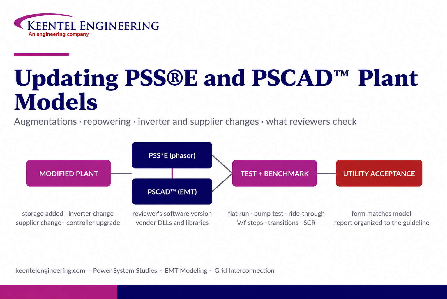
By SANDIP R PATEL
•
September 22, 2026
Learn how PSS®E and PSCAD™ model updates support plant augmentations, repowering, equipment changes, testing, benchmarking, and grid compliance.





