
A Coordinated Electric System Interconnection Review—the utility’s deep-dive on technical and cost impacts of your project.
Challenge: Frequent false tripping using conventional electromechanical relays
Solution: SEL-487E integration with multi-terminal differential protection and dynamic inrush restraint
Result: 90% reduction in false trips, saving over $250,000 in downtime
ERCOT enforces all of the above through simulation, which means your model is your compliance case. The bar is now high:
- Whole-facility scope. The model must represent everything the IT load, the UPS and power conversion, the cooling plant, the protection and control systems in formats compatible with ERCOT's study platforms (PSS/E, PSCAD, TSAT).
- Real control loops, not approximations. Generic textbook representations are unacceptable. The model must capture the actual inner control behavior of your power electronics.
- Hardware-validated converter models. For electronic loads, the PSCAD model must be benchmarked against actual hardware testing including voltage ride-through and subsynchronous response. A model assembled from standard PSCAD library blocks fails by definition, because a generic block has never been tested against your vendor's hardware. The good news: validation is a hardware-type test, so results for a given converter product are reusable across every facility that uses it.
- Format migration. Facilities that previously submitted the older composite load model (CMLD) format must transition to EPRI's PERC1 format.
- Three checkpoints. Models are reviewed before the stability study begins (no model, no study), before each quarterly stability assessment, and for electronic loads one final time before energization, when you must submit as-built models with a documented comparison against the previously studied data and a sworn attestation that the model matches actual field settings. ERCOT's review takes 10 business days, extendable by 20 put it on your critical path.
- A living obligation. Change your technology, controls, or relay settings in a way that affects ride-through including converting a crypto mining site to an AI data center — and you've triggered a new interconnection study, even if your megawatts don't change.
| Parameter | Detail |
|---|---|
| System | 230 kV / 138 kV transmission corridors, wind and wet-snow icing exposure |
| Data basis | 15 years of minute-resolution forced-outage records + regional weather observations |
| Core methods | Event grouping, MVA performance curves, time-to-95%-restore, area outage rate curves, fragility modeling, rerun-history benefits, exceedance and log-domain risk metrics |
| Headline result | ≈85% of maximum resilience benefit at 60% of original capital; worst-event restoration window cut from 11 days to 5 in rerun-history terms |
| Decision supported | Capital portfolio selection; resilience plan filing; post-investment verification framework |
| System / Topic | Governing Standard(s) | What It Controls |
|---|---|---|
| Overall plant electrical distribution | IEEE 141 (Red Book); IEEE 666 | Distribution architecture, voltage selection, design of generating station auxiliary service systems |
| Power system studies | IEEE 399 (Brown Book); IEEE 551 | Load flow, symmetrical/asymmetrical short circuit, motor starting methodologies down to the lowest LV panelboard |
| Protection & coordination | IEEE 242 (Buff Book); IEEE 3004.5; IEEE C37 series | Generator relaying (21, 59N, 87G), time-current coordination, selective clearing between LV and MV tiers |
| GSU / UAT / SST transformers | IEEE C57.12.00 and C57 family | Transformer ratings, impedance, testing, loading |
| HV switchyard breakers | IEEE C37.06 | AC high-voltage circuit breaker preferred ratings |
| MV switchgear (13.8 kV) | IEEE C37.20.2; IEEE C37.20.7 | Metal-clad construction, compartmentalization, vacuum breakers; arc-resistant design with plenum venting |
| MV cable | UL 1072; ICEA S-93-639 (NEMA WC 74) | Type MV-105 shielded cable, 133% insulation level for HRG systems |
| LV switchgear (480 V) | IEEE C37.13; UL 1558 | Metal-enclosed LV power circuit breaker switchgear to 635 V, draw-out ACBs with electronic trip units |
| Motor control centers | UL 845; NEMA ICS 18 | LV-MCC construction, MCCB/MCP protection for motors under ~200 HP |
| Motors | NEMA MG-1 | Motor performance, starting characteristics, service factors |
| DC & battery systems | IEEE 485; IEEE 946 | Lead-acid battery sizing (125/250 VDC), DC auxiliary system design |
| Grounding | IEEE 80; IEEE 142 (Green Book) | Ground grid step/touch potential limits; system grounding including high-resistance grounding |
| Lightning protection | IEEE 998 | Direct-stroke shielding of switchyard and outdoor generator structures |
| Arc flash & electrical safety | IEEE 1584; NFPA 70E | Incident energy calculation; worker safety boundaries and PPE |
| Fire protection | NFPA 850 | Fire protection and risk management for combustion turbine generating plants |
| Installation code | NEC (NFPA 70); NESC | Wiring methods inside the plant fence; overhead/outdoor clearances at the switchyard |
| Interconnection & compliance | FERC LGIP; NERC MOD-025/026/027, PRC-019/024/029, FAC-008 | Interconnection process, model validation, protection/ride-through coordination, facility ratings |
| IFC / Construction Deliverable | Purpose |
|---|---|
| Stamped IFC packages | Legal basis for construction; P.E. responsible charge |
| Final relay settings & TCCs | Protection as-installed matches the coordination study |
| Calculation archive | Owner records; NERC audit evidence trail |
| Commissioning procedures | Safe, sequenced energization; MOD field testing |
| Construction support | RFIs, field changes, FAT/SAT witness |
| As-builts & model handoff | Operating baseline; future study currency |
| Metric | Outcome |
|---|---|
| Defects found pre-occupancy | Three topology defects and one settings-mismatch family corrected before load migration; the shared-switchboard defect alone would have invalidated the concurrently-maintainable claim on day one |
| IST findings | Fourteen additional discrepancies surfaced under scenario testing (control logic, alarm mapping, one generator sequencing fault) — all closed before handover instead of during operations |
| Black-building test | Passed on second execution; the first attempt exposed the generator sequencing fault under true block load, exactly the failure the compressed plan would never have found |
| Handover quality | Operations team certified on the actual failure scenarios; corrected EOPs and settings documentation delivered as controlled documents |
| Business outcome | Occupancy proceeded three weeks behind the original date — against an independent estimate that the uncorrected sequencing fault carried a high probability of a full facility outage within the first year |
Part 2 — Frequently Asked Questions: Large Load Interconnection
An electric grid must remain in continuous balance — generation onto the grid must equal consumption from it at every instant. PJM achieves this balance, and prices it, through a layered market architecture. Each layer operates on a different time horizon, and each one touches project economics differently.
| Domain | Key Standards / Codes | What They Govern |
|---|---|---|
| Fire safety | NFPA 855; UL 9540 / UL 9540A | Installation requirements, separation, gas management; system safety listing and thermal-runaway fire testing |
| Grid interconnection | IEEE 1547 (distribution); IEEE 2800 (transmission IBRs) | Ride-through, reactive capability, power quality, and performance at the point of interconnection |
| Power quality | IEEE 519 | Harmonic distortion limits at the PCC |
| Protection & grounding | IEEE 80 / 81 / 142; C37 series | Grounding system design and testing; protective relaying |
| Reliability compliance | NERC standards (incl. PRC ride-through requirements) | Registered-entity obligations for grid-connected storage |
Neutral Grounding Resistor (NGR) Sizing
Aug 20, 2026 | Blog
A US Engineering Guide to IEEE, ANSI, and NEC Practice
Power Systems Design | Technical Guide, FAQ and Case Studies | August 2026
NGR sizing looks like a one-line calculation. Divide line-to-neutral voltage by the ground-fault current you want, and you have your resistance. That formula is correct, and it is also about 15% of the actual engineering.
The other 85% is everything the formula does not tell you: whether your target current is defensible in the first place, whether the resistor must survive ten seconds or ten years, whether your relaying can actually see the current you selected, and whether the NEC will let you build it at all.
This guide works through the full sizing process on US voltage classes with US governing standards — IEEE C57.32, IEEE 3003.1, IEEE C62.92, and NEC Article 250 — with two complete worked examples: a 13.8 kV low-resistance grounded industrial bus and a 480 V high-resistance grounded system. It closes with a detailed FAQ and three anonymized case studies.
1. What an NGR actually does
A neutral grounding resistor sits between a wye-connected source neutral — transformer secondary or generator — and ground. During a line-to-ground fault, it is the dominant impedance in the zero-sequence path, so it, not the system, decides how much ground-fault current flows.
Every benefit an NGR delivers traces back to that single fact:
| Benefit | Mechanism |
|---|---|
| Limits ground-fault current | Resistor dominates the zero-sequence path |
| Reduces ground-fault arc-flash energy | Incident energy scales with arcing current and duration |
| Limits transient overvoltage | Resistive damping prevents restriking-arc voltage buildup |
| Protects generator and transformer iron | Core damage scales with I²·t at the fault |
| Reduces mechanical and thermal stress | Lower fault current, lower let-through energy |
| Enables selective ground relaying | A known, stable current is one you can coordinate against |
That last row is the one most often skipped, and it is the one that determines whether the design works in service. An NGR does not merely limit current — it manufactures a predictable current that protection engineers can build a coordination scheme around. Get the value wrong in either direction and the resistor still limits current beautifully while the relays either never see the fault or trip on load unbalance.
The grounding spectrum
US practice recognizes a continuum, not a binary. Per IEEE Std C62.92.2-2017, in order of increasing available ground-fault current:
- Resonant grounded (ground-fault neutralizer / Petersen coil) — rare in US industrial work
- Ungrounded — no intentional connection; capacitively coupled
- High-resistance grounded (HRG) — typically ≤ 10 A
- Low-resistance grounded (LRG) — 100 A to 1000 A, 400 A typical
- Low-inductance grounded
- Effectively grounded (solid) — X₀/X₁ ≤ 3 and R₀/X₁ < 1
The 100–1000 A LRG range and the 400 A typical value are not folklore; they are stated in IEEE Std 142-2007 §1.4.3.2 and carried forward into IEEE Std 3003.1-2019.
2. The formulas — and what the notation actually means
Basic sizing
R = V(L-N) / Ig where V(L-N) = V(L-L) / √3
Combined: R = V(L-L) / ( √3 × Ig )
Two things to be careful about. First, use the maximum system voltage, not the nominal, if your utility or generator regulation can push the bus above nameplate — the resistor sees whatever the neutral shift actually is. Second, The ground-fault current that results is not exactly your target, because detailed short circuit analysis may be required when impedance effects become significant. At LRG levels the error is small; at HRG levels it is negligible. At low resistance values approaching solidly grounded, it stops being negligible and you need the full symmetrical-component calculation.
The charging-current constraint (HRG only)
This is the constraint most people get backwards, and it is the one that decides whether HRG is even feasible on your system. IEEE Std 142-2007 §1.4.3.1, repeated verbatim in IEEE 3003.1-2019:
"The value of the resistor is selected to limit the current, I_R, to a magnitude equal to or slightly greater than the total capacitance charging current, 3I_C0."
Ir ≥ 3 Ic0. The notation matters. Ic0 is the per-phase zero-sequence capacitive charging current. 3Ic0 is the system total. Writing "Ir ≥ Ic0" is only correct if you have quietly redefined Ic0 as the total, which contradicts IEEE usage and will confuse whoever reviews your calculation. Use 3Ic0 and state the definition.
Why the constraint exists: if the resistive component of ground-fault current does not at least equal the capacitive component, the arc at the fault can restrike and pump energy into the system L-C circuit. The resistor exists to damp that. Undersize it — meaning too high a resistance, too little current — and you have built an expensive ungrounded system.
Estimating 3Ic0. You sum contributions from every capacitive element. Typical screening values:
| Source | Charging current contribution |
|---|---|
| Shielded cable, 600 V and 2.4 kV | 0.05 – 0.30 A per 1000 ft |
| Shielded cable, 6.9 kV XLPE | 0.55 – 0.85 A per 1000 ft |
| Shielded cable, 13.8 kV | 0.23 – 1.15 A per 1000 ft |
| Transformers | 0.05 A per MVA |
| Motors, low voltage | 0.10 A per 1000 HP |
| Motors, medium voltage | 0.01 A per 1000 HP |
| Surge capacitor sets | 0.78 – 2.25 A per set |
A cruder rule of thumb: 0.5 A per 1000 kVA at 600 V and below, 1.0 A per 1000 kVA above 1000 V. Use it for feasibility screening, not for a final specification — the cable footage drives everything, and two plants with identical transformer capacity can differ by an order of magnitude in charging current.
Measure it if you can. On a retrofit, the reliable method is a staged single-phase-to-ground connection through a known resistance with the system energized and unloaded, or a direct capacitance measurement. Estimated charging current has a wide error band, and HRG sizing has no margin to spare on the low side.
3. Worked Example A — 13.8 kV low-resistance grounded industrial bus
Design intent: a 13.8 kV switchgear lineup feeding MV motors and unit substations in a process plant. Ground faults must be cleared quickly and selectively; running through a ground fault is not desired or permitted by the process.
Step 1 — Line-to-neutral voltage
V(L-N) = 13,800 / √3 = 7,967 V
Step 2 — Select the target ground-fault current
400 A. This is the IEEE-stated typical value for LRG, and on a system with several thousand feet of 13.8 kV shielded cable it comfortably exceeds 3Ic0 (which will be on the order of 3–8 A here), so the resonance constraint is satisfied by an enormous margin. The binding constraint at LRG is not charging current — it is relay sensitivity and equipment damage.
Step 3 — Resistance
R = 7,967 / 400 = 19.9 Ω → specify 20 Ω. At 20 Ω the initial ground-fault current is 7,967 / 20 = 398 A, which is fine.
Step 4 — Time rating
10 seconds. Ground faults on this bus are cleared by 51G in well under 1 second, and 10 s is the standard short-time rating that gives comfortable margin over breaker failure timing.
Step 5 — Thermal check
P(initial) = I²R = 400² × 20 = 3,200,000 W = 3.2 MW
Now read that number carefully, because this is where the widely circulated version of this calculation goes off the rails. 3.2 MW is not a rating. It is the instantaneous dissipation at t = 0, and it decays as the resistor heats and its resistance rises. A 400 A / 10 s unit can be down to roughly 250 A by the end of its rated 10 seconds. You will not find "3.2 MW" on any manufacturer data sheet, and you should not put it in a specification.
What actually goes on the nameplate:
| Nameplate parameter | Value |
|---|---|
| Rated voltage (line-to-neutral) | 7,967 V |
| Rated initial current | 400 A |
| Resistance | 20 Ω |
| Time rating | 10 seconds |
| Temperature rise | 760 °C over 30 °C ambient |
| System voltage | 13.8 kV |
| Enclosure | NEMA 3R, outdoor |
Step 6 — Protection
- 51G on a dedicated CT in the NGR neutral connection. Pickup at roughly 10% of 400 A, coordinated with downstream feeder ground relays.
- 50G / 51G on feeders using core-balance (window) CTs, which give far better sensitivity than residual connection at these current levels.
- NGR continuity monitoring. An open NGR converts an LRG system into an ungrounded system silently, with no alarm and no operational symptom until the first ground fault produces overvoltages the system was never insulated for. Continuity monitoring is inexpensive and it is the single highest-value accessory on an LRG installation.
4. Worked Example B — 480 V high-resistance grounded system
Design intent: a 480 V distribution system serving critical process and IT load. A single ground fault must alarm, not trip. Operations locate and clear it during the next planned window.
Step 1 — Line-to-neutral voltage
V(L-N) = 480 / √3 = 277 V
Step 2 — Estimate total charging current, 3Ic0
| Element | Quantity | Rate | Contribution |
|---|---|---|---|
| 600 V shielded cable | 8,000 ft | 0.15 A / 1000 ft | 1.20 A |
| Transformers | 5 MVA total | 0.05 A / MVA | 0.25 A |
| LV motors | 3,000 HP | 0.10 A / 1000 HP | 0.30 A |
| Surge suppressor set | 1 set | 0.78 A / set | 0.78 A |
| Total 3Ic0 | ≈ 2.5 A |
Step 3 — Select Ir
Ir must be ≥ 3Ic0 = 2.5 A. Select 5 A — roughly 2× the estimated charging current, which covers estimation error and future cable additions without pushing the fault current high enough to cause meaningful damage at the fault point.
Step 4 — Resistance
R = 277 / 5 = 55.4 Ω → specify 55 Ω (Ir = 5.0 A)
Step 5 — Time rating: CONTINUOUS
This is the critical difference from Example A, and it is where the popular version of this calculation is simply wrong. HRG exists so the system can keep running with a ground fault on it while operations locate the fault. The resistor must therefore carry its full rated current indefinitely. IEEE C57.32 continuous duty limits temperature rise to 385 °C over 30 °C ambient, versus 760 °C for short-time ratings — a different resistor, a different thermal design, a different price.
Post Glover states it plainly: continuous-duty rating is required "when the service continuity (alarm only, first fault) is prime concern." Any guidance that says continuous duty is not normally required is describing LRG and mislabeling it as universal.
Step 6 — Power dissipation
P = I²R = 5² × 55 = 1,375 W ≈ 1.4 kW, continuous
Compare: Example A produces 3.2 MW that exists for ten seconds and is not a rating. Example B produces 1.4 kW that exists forever and is a real, meaningful thermal design number. This is exactly why the industry specifies NGRs by voltage, current, and time — never by kilowatts.
Step 7 — Code compliance check, NEC 250.36
In the 2023 NEC, 250.36 is titled "Impedance Grounded Systems — 480 Volts to 1000 Volts." (It was "High-Impedance Grounded Neutral Systems" in the 2020 and earlier editions — a retitle worth noting in any spec that cites it.) Three conditions must be met:
- Only qualified persons service and maintain the installation
- Ground detectors are installed
- Line-to-neutral loads are not served
Condition 3 kills more HRG retrofits than any other single factor. If any 277 V lighting or single-phase load is fed line-to-neutral from that system, you cannot convert it to HRG without re-feeding those loads from a separate solidly grounded source. Confirm this before you design anything.
For systems above 1000 V, the governing section is 250.187, "Impedance Grounded Systems" — same three conditions, plus a requirement that the impedance grounding conductor be insulated for the maximum neutral voltage (57.7% of phase-to-phase on a three-phase wye).
Step 8 — Detection and fault location
- 59G / device 64 neutral overvoltage or ground detection for the alarm
- A pulsing contactor across part of the resistor, which modulates the ground-fault current so a clamp-on ammeter can trace the faulted feeder while the plant runs
- Do not install a trip on
first ground fault. If you do, you have paid for HRG and built LRG.
5. Side by side: HRG vs LRG
| Comparison Parameter | High-Resistance Grounding | Low-Resistance Grounding |
|---|---|---|
| Ground-fault current | ≤ 10 A typical (25 A at 480–600 V) | 100 – 1000 A; 400 A typical |
| First ground fault | Alarm, keep running | Trip, clear in < 1 s |
| Resistor duty | Continuous | 10 seconds typical |
| Temp rise limit (IEEE C57.32) | 385 °C over 30 °C | 760 °C over 30 °C |
| Typical voltage range | 480 V – 15 kV class | 2.4 kV – 34.5 kV |
| Charging current constraint | Binding — Ir ≥ 3Ic0 | Satisfied by a wide margin |
| Line-to-neutral loads | Prohibited (NEC 250.36) | Prohibited on the impedance-grounded system |
| Primary relaying | 59G / 64 ground detection | 51G / 50G, core-balance CTs |
| Typical applications | Data centers, process plants, continuous manufacturing, generators | Utilities, large motors, generators, MV distribution |
| Main benefit | Uptime; near-elimination of ground-fault arc energy | Fast selective clearing; large-machine protection |
| Main limitation | Feasible only when 3Ic0 is small | Fault current still damaging at the fault point |
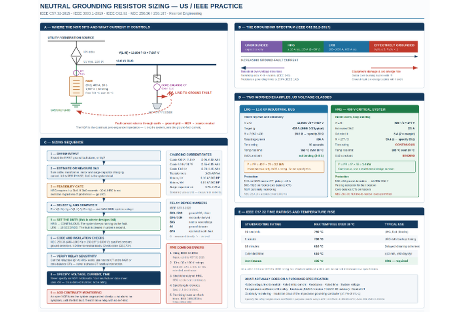
Figure 1, on the following page, summarizes the whole method: where the resistor sits, the grounding spectrum, the nine-step sizing sequence, both worked examples, and the IEEE C57.32 rating table.
FIGURE 1 — NGR sizing to US / IEEE practice: placement, grounding spectrum, sizing sequence, worked examples, and rating table
Illustrative design guidance — not a substitute for a project-specific grounding and coordination study.
6. Five things worth correcting in the popular NGR guides
Most of what circulates on this topic is directionally right. These specific items are not, and each of them has a cost.
1. The IEEE standard number has changed
IEEE Std 32-1972 (R1997) is superseded. The governing document is IEEE Std C57.32-2015, "IEEE Standard for Requirements, Terminology, and Test Procedures for Neutral Grounding Devices," with amendment C57.32a-2020 adding a neutral grounding resistors clause. Both are now listed as Inactive-Reserved by IEEE SA, which is a records-status flag rather than a withdrawal — they remain the referenced documents in practice, and specifications should cite them by number and year.
2. The standard time ratings are not 10 / 30 / 60 seconds
The IEEE-enumerated set is 10 seconds, 1 minute, 10 minutes, extended time, and continuous. ("Extended time" means 10 minutes or more, not exceeding 90 days per year in aggregate.) Vendors will build a 30-second unit, and there is nothing wrong with buying one, but do not present 30 s as a standard IEEE rating in a specification — it invites a bid clarification you do not need.
3. Temperature rise limits pair differently than commonly shown
Per IEEE C57.32, above 30 °C ambient: 10 s → 760 °C, 1 min → 760 °C, 10 min → 610 °C, extended → 610 °C, continuous → 385 °C.
4. "Continuous duty is not normally required" is wrong for HRG
See Example B. It is true for LRG and false for the application where the resistor matters most.
5. kW is a derived quantity, not a specification
Every manufacturer — Post Glover, I-Gard, Filnor, Powerohm — specifies by rated voltage, rated initial current, and rated time. Kilowatts appear on no data sheet. Publishing a "635 kW resistor" invites a procurement conversation that goes nowhere.
One thing the popular guides get right: the charging-current criterion Ig ≥ 3Ic is correct and matches IEEE 142 / 3003.1 exactly. It deserves more prominence than it usually gets, not less.
And one nuance about arc flash
NGRs dramatically reduce ground-fault arc energy — that is real, and it is the single strongest safety argument for HRG. But IEEE Std 1584-2018, "IEEE Guide for Performing Arc-Flash Hazard Calculations," models three-phase arcing faults only. Single-phase and line-to-ground arcing faults are explicitly outside its scope. Its stated applicability is 208 V to 15 kV, three-phase, with bolted fault current from 700 A to 106 kA.
The practical consequence: installing an NGR does not lower the calculated incident energy on your arc-flash labels, because those labels are computed from three-phase bolted fault current, which the NGR does not touch. The NGR reduces the
likelihood and severity of the ground-fault event that initiates most arcing faults in the field. That is a genuine and valuable risk reduction. It is not a label change, and anyone who promises you one is confusing two different things.
7. Design checks that catch real problems
Relay sensitivity
Can your ground relay actually see Ir? On a 5 A HRG system, a 5 A ground-fault current is below the pickup of most conventional overcurrent elements and well below normal residual unbalance on a phase-CT residual connection. HRG requires either neutral-connected sensing at the resistor or core-balance CTs on feeders — never a residual connection from phase CTs.
Resistance drift with temperature
Relay coordination depends on the fault current staying near its rated value. IEEE C57.32 caps the resistance increase at 67%, but the alloy matters: purpose-made resistance alloys run around 0.00024–0.00036 Ω/°C, while general-purpose stainless (AISI 304 at 0.00092, AISI 430 at 0.00146) drifts several times more. Specify the temperature coefficient, not just "stainless steel."
Transient overvoltage
On an ungrounded system, restriking ground faults are cited in IEEE Std 242 (Buff Book) as capable of producing overvoltages of six to eight times normal phase voltage. IEEE 142-2007 §1.4.3.2 states that both high- and low-resistance grounding are designed to limit transient overvoltages to 250% of normal. Keep these separate from the steady-state effect: during a sustained single line-to-ground fault, the unfaulted phases rise to line-to-line voltage — 173% of normal line-to-ground — on any impedance-grounded or ungrounded system. That 173% is why cable and surge arrester insulation levels must be checked before an HRG conversion.
Cable and arrester insulation rating
Because the unfaulted phases sit at 173% during a sustained fault, an HRG system needs 133% or 173% insulation-level cable depending on how long faults are permitted to persist, and surge arresters rated for an ungrounded-system duty. This item alone has stopped more than one HRG retrofit at the cable-schedule review.
Neutral conductor insulation
NEC 250.187 requires the impedance grounding conductor be insulated for the maximum neutral voltage — 57.7% of phase-to-phase.
Effectively grounded verification
If a utility interconnection agreement requires an effectively grounded source, you must demonstrate X₀/X₁ ≤ 3 and R₀/X₁ < 1 (coefficient of grounding ≤ 80%). Resistance grounding by definition does not meet this. This is a frequent and expensive collision on generation interconnection projects — see Case Study 3.
Generator neutrals
IEEE C62.92.2-2017 recommends limiting generator ground-fault current to 5 A to 15 A under high-resistance grounding, because "iron burning and damage depend mainly on fault current magnitude and duration." A solidly grounded generator can see ground-fault current exceeding its three-phase fault current, since zero-sequence impedance is typically the lowest of the three sequence impedances — and the damage lands in the laminated stator core, which is the most expensive thing in the machine to repair. Where generators are paralleled, use separate NGRs per machine to avoid circulating third-harmonic current.
8. Anonymized case studies
The following are anonymized and composited from typical engagements. Figures are representative of the scenarios described and have been rounded and adjusted; they do not identify any specific client or facility.
Case Study 1 — Colocation data center: HRG retrofit blocked by 277 V lighting
Situation. A 30 MW Mid-Atlantic colocation facility operated its 480 V mechanical and house distribution as a solidly grounded system. Two unplanned outages in eighteen months traced to ground faults in pump-room conduit that tripped upstream and dropped mechanical cooling. The client asked for a high-resistance grounding conversion to eliminate first-fault trips.
What the analysis found
Charging current was manageable — roughly 3.5 A total on the mechanical distribution — so a 5 A HRG design at 55 Ω continuous was straightforward on paper. The problem was NEC 250.36 condition 3: the same 480Y/277 V system fed several hundred 277 V lighting fixtures line-to-neutral across the building. HRG was not permissible on that system as built.
What was done
Rather than abandon the conversion, the system was split. The mechanical and process distribution — where the ground faults were actually occurring, and where uptime mattered — was re-fed from a dedicated 480 V transformer with no line-to-neutral loads and high-resistance grounded at 5 A continuous, with pulsing fault location and 59G alarm to the BMS. The 277 V lighting load stayed on a separate, solidly grounded 480Y/277 V transformer where trips were operationally tolerable.
Outcome
Ground faults on the mechanical system now alarm instead of tripping, and are located during business hours using a clamp meter and the pulsing contactor. The additional transformer added meaningful cost relative to a straight NGR installation, which is exactly why the code check belongs at the front of the project, not at the permit review.
Engineering takeaway
Check NEC 250.36 condition 3 before you size anything. The resistor calculation is the easy part; the load inventory is what determines whether HRG is buildable.
Case Study 2 — Gulf Coast refinery: the 13.8 kV NGR that had been open for two years
Situation. A refinery experienced simultaneous cable terminator failures at two locations on a 13.8 kV bus during what should have been a routine single line-to-ground fault. The immediate damage was contained, but the failure pattern — multiple remote flashovers from one initiating fault — did not match a resistance-grounded system.
What the analysis found
The NGR on the source transformer neutral had failed open. Post-incident resistance measurement confirmed an open element. Comparison against maintenance records indicated the resistor had most likely been open since the previous turnaround, roughly two years earlier. During that period the 13.8 kV system had been operating ungrounded, with no alarm, no indication, and no operational symptom of any kind. The terminator failures were consistent with restriking-arc transient overvoltages in the range IEEE 242 describes for ungrounded systems — six to eight times normal phase voltage.
What was done
The NGR was replaced with a 20 Ω, 400 A, 10-second unit (7,967 V line-to-neutral rating) and continuity monitoring was installed on every NGR in the facility — a fleet of eleven resistors across the MV system, none of which had monitoring. Ground relay settings were reverified against the restored 400 A design value. Cable terminations at the two failure points and at three other locations showing partial-discharge indications were replaced.
Outcome
The monitoring retrofit cost a small fraction of the terminator replacements from the single event, and detected a second developing high-resistance condition on a different unit within the following year.
Engineering takeaway
An NGR is the only major protective device in a substation that can fail completely, silently, and without consequence — right up until the moment it matters. Continuity monitoring is not an accessory. Treat an unmonitored NGR the same way you would treat a relay with no self-test.
Case Study 3 — 120 MWac utility-scale solar: HRG was never an option
Situation. A 120 MWac PV project in ERCOT proposed high-resistance grounding on its 34.5 kV collector system, reasoning that a single ground fault should not curtail the whole plant. The utility's interconnection requirements simultaneously called for an effectively grounded source at the point of interconnection.
What the analysis found
Two independent problems.
First, charging current. The collector system comprised roughly 28 miles of 35 kV-class shielded cable. Scaling from published 13.8 kV values by voltage and cable capacitance put total charging current on the order of 150 A. To satisfy Ir ≥ 3Ic0, the resistor would have had to pass at least 150 A — which is squarely in the low-resistance band. High-resistance grounding was arithmetically impossible on this system, independent of anyone's preference.
Second, the interconnection requirement. Effective grounding requires X₀/X₁ ≤ 3 and R₀/X₁ < 1. Resistance grounding does not meet that criterion by definition. The two requirements in the project documents were mutually exclusive as written.
What was done
The two requirements were separated by where they apply. The GSU was configured to provide an effectively grounded zero-sequence source at the point of interconnection, satisfying the utility. The collector system was low-resistance grounded at 400 A through a 50 Ω, 10-second NGR (19,919 V line-to-neutral rating), giving fast, selective clearing of collector-circuit ground faults. Feeder ground protection used core-balance CTs at each collector circuit breaker so that a single faulted circuit trips and the remaining circuits keep producing — delivering most of the availability benefit the project had wanted from HRG, through selectivity rather than through riding out the fault.
Outcome
A ground fault on one collector circuit now curtails that circuit only, typically 8–12 MW rather than the full plant. The design cleared utility review without an exception request.
Engineering takeaway
"We want HRG" is a statement about desired behavior, not a design. On large collector systems the charging current usually decides the question before anyone gets to state a preference. And where an interconnection agreement demands effective grounding, the resolution is almost always to satisfy it at the GSU rather than to argue about the collector system.
9. Frequently asked questions
Q: What is the single most common NGR sizing mistake?
Sizing an HRG resistor without measuring or carefully estimating system charging current. If Ir falls below 3Ic0, the system behaves as an ungrounded system during restriking faults, and you get the transient overvoltages the resistor was purchased to prevent — while the nameplate says everything is fine. The second most common mistake is specifying short-time duty on an HRG system.
Q: Can I convert an existing solidly grounded 480 V system to HRG?
Only if no line-to-neutral loads are served from it (NEC 250.36), only qualified persons maintain it, and ground detectors are installed. In practice, most existing 480/277 V systems feed 277 V lighting line-to-neutral, which disqualifies them until that load is re-fed from a separate source. Also verify cable insulation level and surge arrester ratings, since unfaulted phases will sit at 173% of normal line-to-ground during a sustained fault.
Q: HRG or LRG — how do I choose?
Ask what a first ground fault should do. If the answer is "alarm and let us finish the batch," you want HRG, and you must then confirm 3Ic0 is small enough to make it feasible. If the answer is "trip immediately and selectively," you want LRG. If the system is large enough that 3Ic0 exceeds roughly 10 A, HRG stops being an option regardless of preference — the resistor current required to satisfy Ir ≥ 3Ic0 is no longer "high resistance."
Q: Why is my NGR rated in seconds instead of kilowatts?
Because a resistor's limit is temperature, and temperature is the integral of I²R over time. A 20 Ω resistor dissipating 3.2 MW is perfectly happy for 10 seconds and destroyed in 60. Voltage, current, and time fully define the thermal duty; kW does not. Every major manufacturer specifies this way.
Q: What happens if the NGR fails open?
The system silently becomes ungrounded. There is no alarm, no measurable change in operation, and no symptom — until the first ground fault, when restriking arcs produce transient overvoltages up to 6–8× normal on a system whose insulation was coordinated for a resistance-grounded duty. Multiple flashovers at remote points can follow, typically at cable terminations and motor windings. NGR continuity monitoring is inexpensive and should be considered mandatory.
Q: Does adding an NGR reduce my arc-flash incident energy labels?
No. Arc-flash incident energy per IEEE 1584-2018 is computed from three-phase arcing current, and IEEE 1584-2018 does not model single-phase or line-to-ground arcing faults at all. An NGR does not change three-phase fault current, so the label value does not change. What the NGR does is dramatically reduce the energy of ground-fault arcing events, which are the initiating event for a large share of real arcing faults. Real risk reduction; no label change.
Q: Where exactly does the NGR go?
Between the wye-point neutral of the source — transformer secondary or generator — and the ground grid. One resistor per grounded source. If a bus is fed by two transformers that can be paralleled, you either need a scheme that grounds through only one NGR at a time, or you accept the parallel combination and size for it. On generators, use one NGR per machine.
Q: Can I use a grounding transformer instead?
Yes, and on delta-connected or ungrounded systems where no neutral exists, you must. A zig-zag or wye-delta grounding transformer creates a neutral point; the resistor then goes in that neutral, or is placed in the secondary of a wye-broken-delta arrangement as a "loading resistor," which lets you use a much lower-voltage resistor. IEEE C57.32 covers grounding transformers as well as resistors.
Q: What relay device numbers apply?
Per IEEE Std C37.2-2022: 50G/51G for instantaneous and time ground overcurrent, 50N/51N for the residually derived equivalent, 59G for neutral overvoltage, 64 for ground detection, and 87N (also written 64REF/87REF) for restricted earth fault. The G and N suffixes differ by sensing method — G means directly measured by a dedicated core-balance or neutral sensor; N means residually derived from three phase CTs. On HRG systems, always G.
Q: How much current should a 4.16 kV system be limited to?
It depends entirely on the design intent, but for orientation: at 4,160 V, V(L-N) = 2,402 V. A 400 A LRG design gives R = 6 Ω. A 15 A HRG design gives R = 160 Ω. Manufacturer HRG practice for the 2.4–4.16 kV class typically lands around 15 A total ground current, versus 25 A at 480–600 V and 10 A at 6.9–13.8 kV.
Q: Do NGRs need to be tested or maintained?
Yes. Resistance measurement should be part of the routine electrical maintenance program, along with visual inspection for element cracking, corrosion, and moisture ingress in outdoor NEMA 3R enclosures. Continuity monitoring covers the catastrophic open-circuit case in real time, but it does not detect gradual resistance drift, which shifts your ground-fault current away from the value your coordination study assumed.
Q: What standards should I actually cite in a specification?
IEEE Std C57.32-2015 and C57.32a-2020 for the device itself; IEEE Std 3003.1-2019 for system grounding practice (it replaced IEEE 142-2007, which went inactive in 2021); IEEE Std C62.92 parts I, II and V for grounding classification and generator application; NEC 250.36 for 480–1000 V and 250.187 for over 1000 V; IEEE C37.2-2022 for device function numbers; IEEE 1584-2018 for arc-flash calculations. CSA C22.2 No. 295 and IEC 60076-25:2023 apply on Canadian and international projects respectively.
Q: Is 600 V a US system voltage?
600 V is the Canadian standard nominal (CSA); the US ANSI C84.1 preferred low-voltage three-phase nominals are 208Y/120 and 480Y/277. If you are writing a specification that will be used on both sides of the border, say so explicitly rather than listing "480/600 V" as though they were interchangeable.
10. Standards reference
| Standard | Scope |
|---|---|
| IEEE Std C57.32-2015 (+ C57.32a-2020) | Neutral grounding devices — requirements, terminology, test procedures. Supersedes IEEE Std 32-1972 |
| IEEE Std 3003.1-2019 | System grounding of industrial and commercial power systems. Replaced IEEE 142-2007 (inactive 2021) |
| IEEE Std 142-2007 (inactive) | Green Book — still the most-cited source for the 100–1000 A LRG range and the 250% overvoltage limit |
| IEEE Std C62.92.1-2016 / .2-2017 / .5-2020 | Neutral grounding in electrical utility systems — introduction, generators, transmission |
| IEEE Std 242 (Buff Book) | Protection and coordination; source of the 6–8× ungrounded overvoltage figure |
| IEEE Std 1584-2018 | Arc-flash hazard calculations. Three-phase only, 208 V–15 kV, 700 A–106 kA |
| IEEE Std C37.2-2022 | Device function numbers, acronyms, contact designations |
| NEC (NFPA 70) 250.36 | Impedance grounded systems, 480 V to 1000 V |
| NEC (NFPA 70) 250.187 | Impedance grounded systems, over 1000 V |
| ANSI C84.1-2020 (R2025) | System and utilization voltage ratings, 60 Hz |
| CSA C22.2 No. 295 | Neutral grounding devices (Canada) |
| IEC 60076-25:2023 | Power transformers — neutral grounding resistors (international) |
Closing
The NGR sizing formula is trivially simple and almost never the reason a grounding design fails. Designs fail because charging current was estimated instead of measured, because a continuous-duty application was specified with a short-time resistor, because a 277 V lighting circuit made the whole scheme non-compliant, because nobody monitored a device that fails silently, or because two contract documents demanded incompatible grounding classes and nobody reconciled them until the design review.
At Keentel Engineering, system grounding studies are part of the power system studies we deliver alongside substation design, POI interconnection engineering, and owner's engineering for renewable and industrial projects. If you have an NGR specification to review, a grounding class to select, or an interconnection requirement that appears to contradict your plant design, we would be glad to look at it.
KEENTEL ENGINEERING
Tampa, FL · Austin, TX · Sacramento, CA · Baltimore, MD
keentelengineering.com · contact@keentelengineering.com · 813-389-7871
Engineering note: standards editions, section numbers, and quantitative limits cited here were verified against current published sources at time of writing. NEC section numbers are given for the 2023 edition; confirm against the edition adopted in your jurisdiction. Nothing here substitutes for a project-specific grounding and coordination study.

About the Author:
Sandip "Sonny" R. Patel, P.E.
IEEE Senior Member · Founder & CEO, Keentel Engineering
In 1995, Sonny Patel earned his Electrical Engineering degree from the University of Illinois. But degrees don't build legacies — action does.
For three decades, he has worked the power industry from every side of the table: 16 years as a utility engineer at Exelon/Commonwealth Edison; generation leadership across hydroelectric, industrial steam turbine, and a 9 GW renewable fleet; NERC Regional Entity Senior Compliance Engineer and Audit Team Lead, auditing some of the nation's largest utilities; and testing and commissioning lead on equipment up to 765 kV — the very top of the North American grid.
Utility. Generator. Regulator. Consultant. Few engineers have seen all four seats. Fewer still have sat in them.His experience spans nuclear, hydro, conventional generation, renewables, oil and gas, mining — and today's data centers, where he is authoring a three-book series on data center design. He is a Licensed Professional Engineer in six states and a Licensed Electrical Contractor in Florida (Unlimited EC) — he doesn't just design the work; he's qualified to stand behind its execution.Today, as Founder and CEO of Keentel Engineering, Sonny leads 51 engineers delivering substation design, power system studies, NERC compliance, and commissioning — done right, coast to coast.Three decades. Every side of the table. One standard: accountable engineering
Services

Let's Discuss Your Project
Let's book a call to discuss your electrical engineering project that we can help you with.
About the Author:
Sandip "Sonny" R. Patel, P.E.
IEEE Senior Member · Founder & CEO, Keentel Engineering
In 1995, Sonny Patel earned his Electrical Engineering degree from the University of Illinois. But degrees don't build legacies — action does.
For three decades, he has worked the power industry from every side of the table: 16 years as a utility engineer at Exelon/Commonwealth Edison; generation leadership across hydroelectric, industrial steam turbine, and a 9 GW renewable fleet; NERC Regional Entity Senior Compliance Engineer and Audit Team Lead, auditing some of the nation's largest utilities; and testing and commissioning lead on equipment up to 765 kV — the very top of the North American grid.Utility. Generator. Regulator. Consultant. Few engineers have seen all four seats. Fewer still have sat in them.His experience spans nuclear, hydro, conventional generation, renewables, oil and gas, mining — and today's data centers, where he is authoring a three-book series on data center design. He is a Licensed Professional Engineer in six states and a Licensed Electrical Contractor in Florida (Unlimited EC) — he doesn't just design the work; he's qualified to stand behind its execution.Today, as Founder and CEO of Keentel Engineering, Sonny leads 51 engineers delivering substation design, power system studies, NERC compliance, and commissioning — done right, coast to coast.Three decades. Every side of the table. One standard: accountable engineering
Leave a Comment
Thank you for contacting us.
We will get back to you as soon as possible.
We will get back to you as soon as possible.
Oops, there was an error sending your message.
Please try again later.
Please try again later.
Related Posts
By SANDIP R PATEL
•
August 20, 2026
Learn U.S. pole-mounted transformer design requirements, including IEEE, ANSI, and NESC standards, voltage classes, grounding, protection, and DER considerations.
By SANDIP R PATEL
•
August 19, 2026
Understand PRC-023-6 for utility-scale BESS: applicability, the 39-month rule, relay loadability, setting criteria, Category 2 IBRs, and audit evidence.
By SANDIP R PATEL
•
August 18, 2026
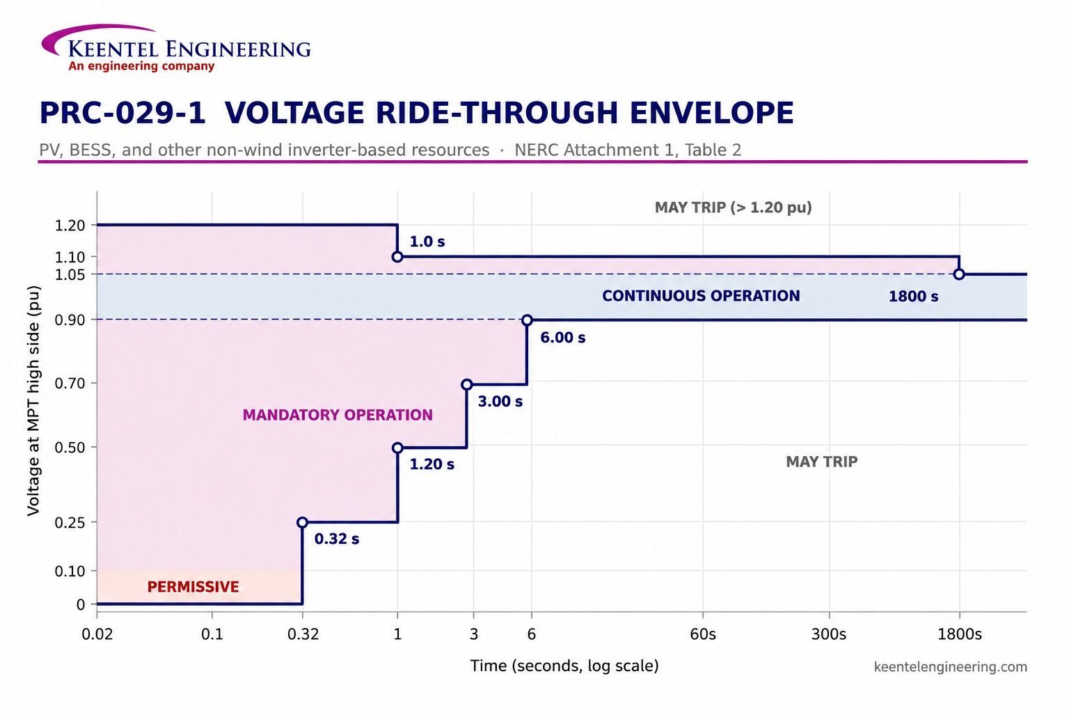
Learn PRC-029-1 compliance requirements for inverter-based resources, including voltage and frequency ride-through, EMT studies, protection settings, and testing.

By SANDIP R PATEL
•
August 17, 2026
A technical guide to solar plant electrical testing, commissioning, I-V curves, thermography, insulation testing, cable tests and performance acceptance.
By SANDIP R PATEL
•
August 16, 2026
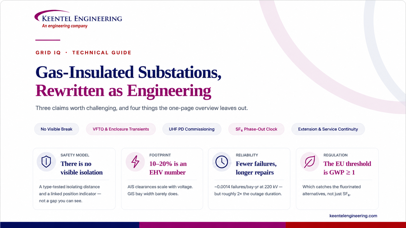
Explore GIS substation engineering, including design, SF6 safety, VFTO, grounding, commissioning, testing, GIS vs AIS, and IEEE/IEC standards.
By SANDIP R PATEL
•
August 16, 2026
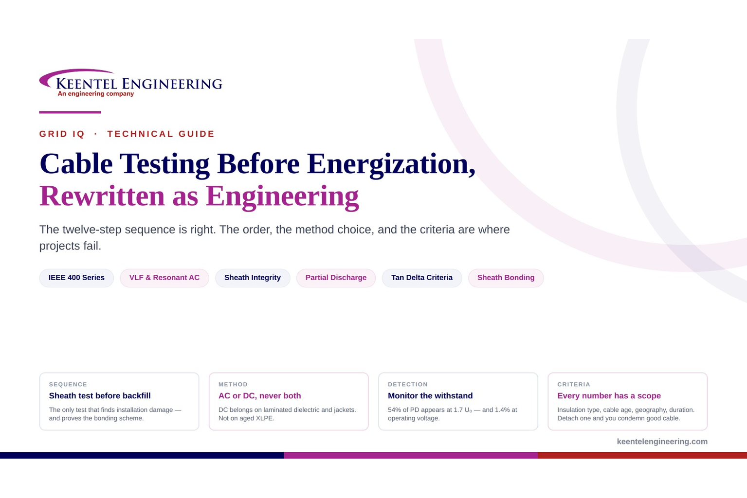
Learn the correct cable testing sequence before energization, including VLF, AC/DC withstand, sheath testing, partial discharge, tan delta, and standards.
By SANDIP R PATEL
•
August 16, 2026
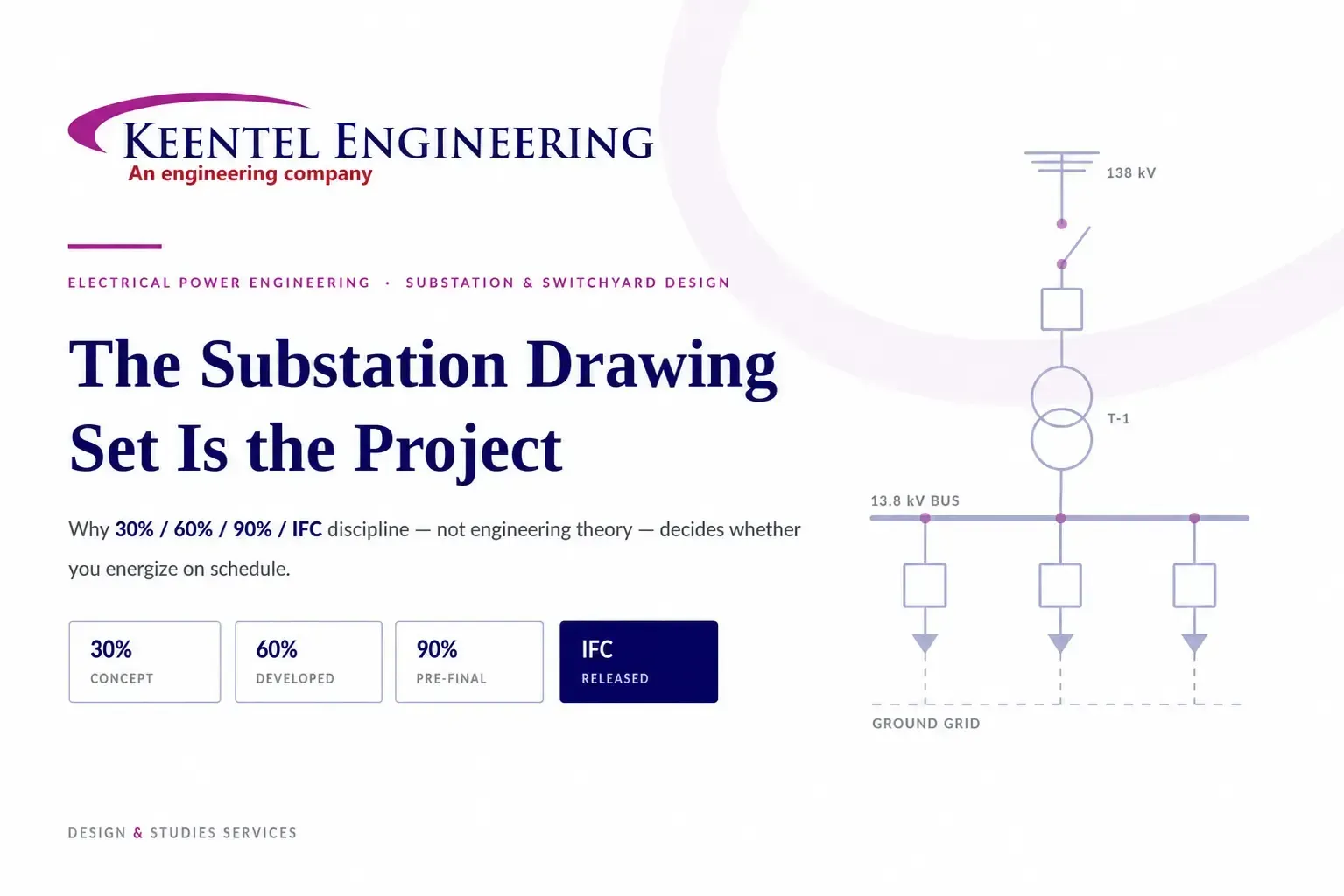
Explore how substation drawing sets are developed, reviewed and controlled through engineering studies, design milestones, QA/QC and final construction release.
By SANDIP R PATEL
•
August 15, 2026
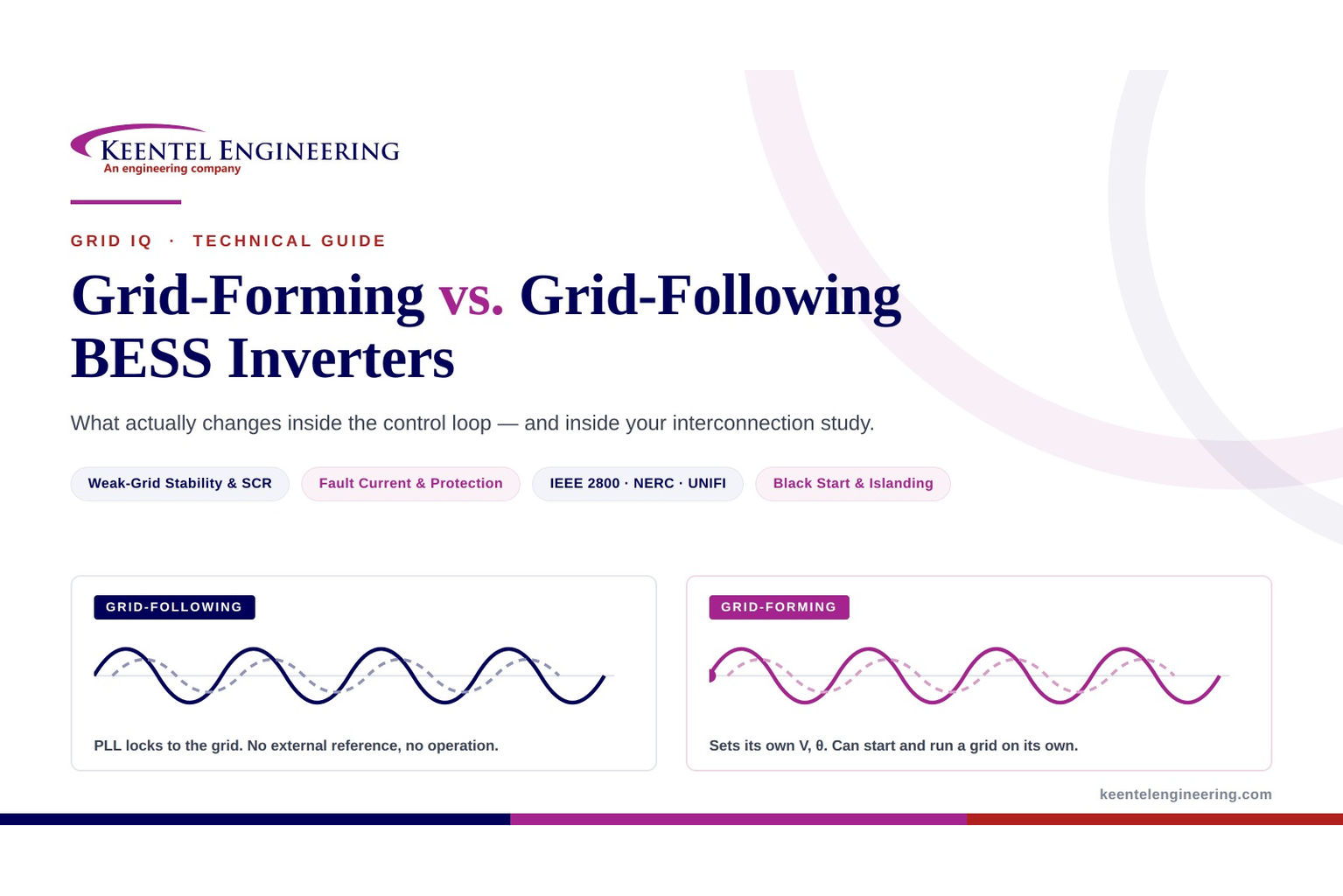
Compare grid-forming vs grid-following BESS inverters, control loops, weak-grid stability, protection, compliance, and interconnection study impacts.
By SANDIP R PATEL
•
August 15, 2026
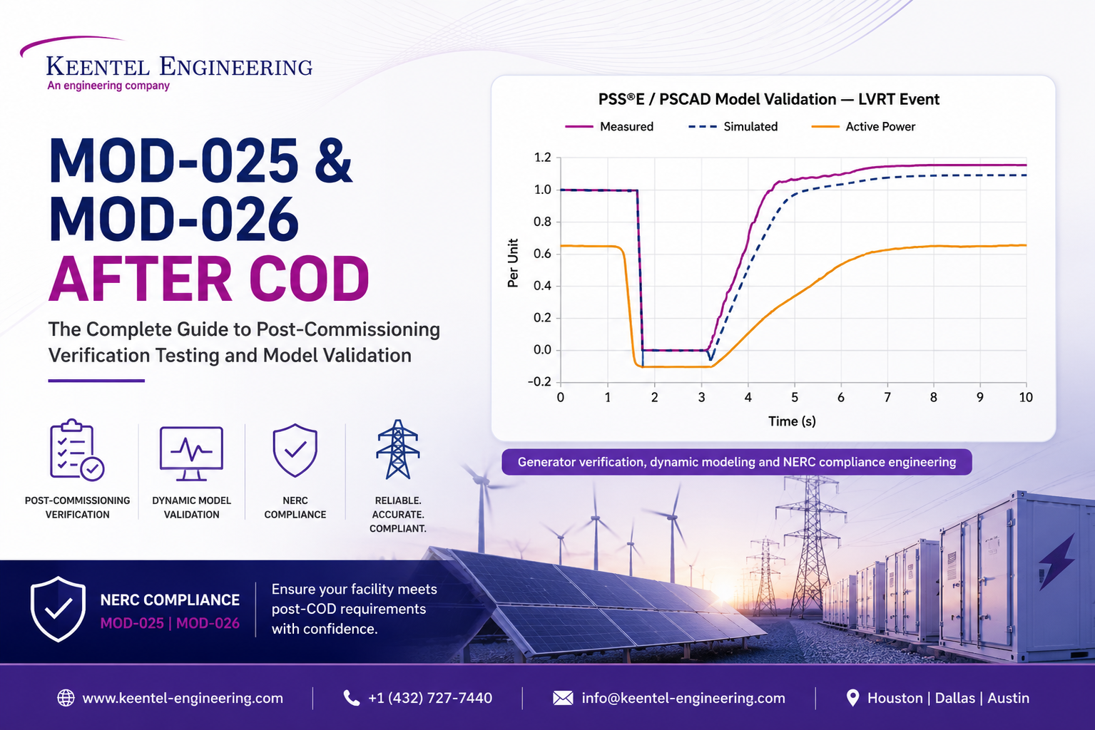
Learn MOD-025 and MOD-026 post-COD requirements for generator capability verification, PSS®E and PSCAD model validation, IBR testing, and NERC compliance.





