
A Coordinated Electric System Interconnection Review—the utility’s deep-dive on technical and cost impacts of your project.
Challenge: Frequent false tripping using conventional electromechanical relays
Solution: SEL-487E integration with multi-terminal differential protection and dynamic inrush restraint
Result: 90% reduction in false trips, saving over $250,000 in downtime
ERCOT enforces all of the above through simulation, which means your model is your compliance case. The bar is now high:
- Whole-facility scope. The model must represent everything the IT load, the UPS and power conversion, the cooling plant, the protection and control systems in formats compatible with ERCOT's study platforms (PSS/E, PSCAD, TSAT).
- Real control loops, not approximations. Generic textbook representations are unacceptable. The model must capture the actual inner control behavior of your power electronics.
- Hardware-validated converter models. For electronic loads, the PSCAD model must be benchmarked against actual hardware testing including voltage ride-through and subsynchronous response. A model assembled from standard PSCAD library blocks fails by definition, because a generic block has never been tested against your vendor's hardware. The good news: validation is a hardware-type test, so results for a given converter product are reusable across every facility that uses it.
- Format migration. Facilities that previously submitted the older composite load model (CMLD) format must transition to EPRI's PERC1 format.
- Three checkpoints. Models are reviewed before the stability study begins (no model, no study), before each quarterly stability assessment, and for electronic loads one final time before energization, when you must submit as-built models with a documented comparison against the previously studied data and a sworn attestation that the model matches actual field settings. ERCOT's review takes 10 business days, extendable by 20 put it on your critical path.
- A living obligation. Change your technology, controls, or relay settings in a way that affects ride-through including converting a crypto mining site to an AI data center — and you've triggered a new interconnection study, even if your megawatts don't change.
| Parameter | Detail |
|---|---|
| System | 230 kV / 138 kV transmission corridors, wind and wet-snow icing exposure |
| Data basis | 15 years of minute-resolution forced-outage records + regional weather observations |
| Core methods | Event grouping, MVA performance curves, time-to-95%-restore, area outage rate curves, fragility modeling, rerun-history benefits, exceedance and log-domain risk metrics |
| Headline result | ≈85% of maximum resilience benefit at 60% of original capital; worst-event restoration window cut from 11 days to 5 in rerun-history terms |
| Decision supported | Capital portfolio selection; resilience plan filing; post-investment verification framework |
| System / Topic | Governing Standard(s) | What It Controls |
|---|---|---|
| Overall plant electrical distribution | IEEE 141 (Red Book); IEEE 666 | Distribution architecture, voltage selection, design of generating station auxiliary service systems |
| Power system studies | IEEE 399 (Brown Book); IEEE 551 | Load flow, symmetrical/asymmetrical short circuit, motor starting methodologies down to the lowest LV panelboard |
| Protection & coordination | IEEE 242 (Buff Book); IEEE 3004.5; IEEE C37 series | Generator relaying (21, 59N, 87G), time-current coordination, selective clearing between LV and MV tiers |
| GSU / UAT / SST transformers | IEEE C57.12.00 and C57 family | Transformer ratings, impedance, testing, loading |
| HV switchyard breakers | IEEE C37.06 | AC high-voltage circuit breaker preferred ratings |
| MV switchgear (13.8 kV) | IEEE C37.20.2; IEEE C37.20.7 | Metal-clad construction, compartmentalization, vacuum breakers; arc-resistant design with plenum venting |
| MV cable | UL 1072; ICEA S-93-639 (NEMA WC 74) | Type MV-105 shielded cable, 133% insulation level for HRG systems |
| LV switchgear (480 V) | IEEE C37.13; UL 1558 | Metal-enclosed LV power circuit breaker switchgear to 635 V, draw-out ACBs with electronic trip units |
| Motor control centers | UL 845; NEMA ICS 18 | LV-MCC construction, MCCB/MCP protection for motors under ~200 HP |
| Motors | NEMA MG-1 | Motor performance, starting characteristics, service factors |
| DC & battery systems | IEEE 485; IEEE 946 | Lead-acid battery sizing (125/250 VDC), DC auxiliary system design |
| Grounding | IEEE 80; IEEE 142 (Green Book) | Ground grid step/touch potential limits; system grounding including high-resistance grounding |
| Lightning protection | IEEE 998 | Direct-stroke shielding of switchyard and outdoor generator structures |
| Arc flash & electrical safety | IEEE 1584; NFPA 70E | Incident energy calculation; worker safety boundaries and PPE |
| Fire protection | NFPA 850 | Fire protection and risk management for combustion turbine generating plants |
| Installation code | NEC (NFPA 70); NESC | Wiring methods inside the plant fence; overhead/outdoor clearances at the switchyard |
| Interconnection & compliance | FERC LGIP; NERC MOD-025/026/027, PRC-019/024/029, FAC-008 | Interconnection process, model validation, protection/ride-through coordination, facility ratings |
| IFC / Construction Deliverable | Purpose |
|---|---|
| Stamped IFC packages | Legal basis for construction; P.E. responsible charge |
| Final relay settings & TCCs | Protection as-installed matches the coordination study |
| Calculation archive | Owner records; NERC audit evidence trail |
| Commissioning procedures | Safe, sequenced energization; MOD field testing |
| Construction support | RFIs, field changes, FAT/SAT witness |
| As-builts & model handoff | Operating baseline; future study currency |
| Metric | Outcome |
|---|---|
| Defects found pre-occupancy | Three topology defects and one settings-mismatch family corrected before load migration; the shared-switchboard defect alone would have invalidated the concurrently-maintainable claim on day one |
| IST findings | Fourteen additional discrepancies surfaced under scenario testing (control logic, alarm mapping, one generator sequencing fault) — all closed before handover instead of during operations |
| Black-building test | Passed on second execution; the first attempt exposed the generator sequencing fault under true block load, exactly the failure the compressed plan would never have found |
| Handover quality | Operations team certified on the actual failure scenarios; corrected EOPs and settings documentation delivered as controlled documents |
| Business outcome | Occupancy proceeded three weeks behind the original date — against an independent estimate that the uncorrected sequencing fault carried a high probability of a full facility outage within the first year |
Part 2 — Frequently Asked Questions: Large Load Interconnection
An electric grid must remain in continuous balance — generation onto the grid must equal consumption from it at every instant. PJM achieves this balance, and prices it, through a layered market architecture. Each layer operates on a different time horizon, and each one touches project economics differently.
| Domain | Key Standards / Codes | What They Govern |
|---|---|---|
| Fire safety | NFPA 855; UL 9540 / UL 9540A | Installation requirements, separation, gas management; system safety listing and thermal-runaway fire testing |
| Grid interconnection | IEEE 1547 (distribution); IEEE 2800 (transmission IBRs) | Ride-through, reactive capability, power quality, and performance at the point of interconnection |
| Power quality | IEEE 519 | Harmonic distortion limits at the PCC |
| Protection & grounding | IEEE 80 / 81 / 142; C37 series | Grounding system design and testing; protective relaying |
| Reliability compliance | NERC standards (incl. PRC ride-through requirements) | Registered-entity obligations for grid-connected storage |
The Substation Drawing Set Is the Project
Aug 16, 2026 | Blog
IN BRIEF
Substation projects rarely fail because someone got the fault current wrong. They fail because a drawing went to the field one revision behind the calculation that governs it, because a 60% set was issued before vendor data arrived, or because nobody could say with certainty which PDF was the current one.
This article breaks down the deliverable architecture of a substation electrical package: a 122-sheet E-series drawing set, the four submittal gates that control it, the twenty engineering studies that feed it, and the folder structure that keeps all of it traceable from kickoff to as-built.
It is the same structure Keentel Engineering uses on every substation package we deliver.
1. The failure mode nobody puts in the lessons-learned report
Ask a substation project manager why the last job slipped and you will hear about long-lead transformers, utility outage windows, or a geotechnical surprise. You will almost never hear the real answer, because it is unglamorous: the engineering deliverables were not under control.
Consider a failure sequence we have walked into more than once. A 13.8 kV feeder relay panel is fabricated from a 60% wiring diagram because the vendor needed to start early. The arc flash study finishes two weeks later and drives an instantaneous setting change, which changes the CT ratio, which changes the panel wiring. The revised sheet is issued — but the fabricator is working from a PDF that was emailed, not transmitted, and the folder it lives in has no revision suffix. The panel arrives at site wired to a superseded drawing. Nobody catches it until functional testing, eleven days before the outage window.
Nothing in that sequence is an engineering error. Every calculation was correct. The failure was entirely one of deliverable architecture: which document is current, who has it, what it depends on, and what had to be finished before it was allowed to be issued.
This is why, at Keentel Engineering, the folder structure and the drawing register are set up
before the first sheet is drafted. They are not administrative overhead. They are the control system for the entire design effort, and they are the first thing we hand a client at kickoff.
WHAT THIS ARTICLE COVERS
Section 2 — why a document structure is an engineering deliverable, not filing.
Section 3 — the four submittal gates (30 / 60 / 90 / IFC) and the exit criteria for each.
Section 4 — the anatomy of a 122-sheet substation electrical drawing set, series by series.
Section 5 — the twenty studies that drive those sheets, and the dependency chain that sets your schedule.
Section 6 — the project folder structure that makes all of it traceable.
Section 7 — six failure modes we see repeatedly, and the control that prevents each one.
2. A folder structure is an engineering deliverable
A substation electrical package is not one document. It is roughly 122 drawing sheets, fourteen calculation packages, twenty study reports, three specification divisions, ten vendor submittal streams, a bill of materials, and a cost estimate — each issued up to four times, each with its own revision history, and most of them dependent on at least one of the others.
Multiply that out and a single substation generates several thousand controlled documents over its design life. Without an imposed structure, that volume degrades in a predictable way: files accumulate in email threads, revisions get distinguished by filename suffixes like "final_v2_REVISED_use-this-one," and the question "is this the current sheet?" becomes unanswerable without a phone call.
The structure that prevents this has three properties. It is decided once, at project setup, before anyone is under schedule pressure. It separates received information from produced information, so client data and vendor prints can never be silently edited. And it makes the milestone the top-level organizing principle inside the drawing folder, so that the 60% set physically cannot be confused with the 90% set.
THE KEENTEL STANDARD
Every Keentel substation project is instantiated from the same folder template on day one — 122 folders across four levels, from 00_Project_Administration through 11_Project_Closeout_and_Archive.
Received data lives under 01_Reference_and_Input_Data and is read-only. Client standards, as-builts, survey, soil resistivity and utility fault duty all land there unaltered, with the date and source they arrived under.
Drawings live under 04_Drawings, subdivided first by milestone — 30%, 60%, 90%, IFC — and only then by file type. A superseded issue is moved to 05_Superseded_and_Void and stamped, never deleted and never left in place.
We hand this structure, and the live drawing register that indexes it, to the client at kickoff. You always know what exists, what revision it is at, and where it sits.
3. The four gates: 30% / 60% / 90% / IFC
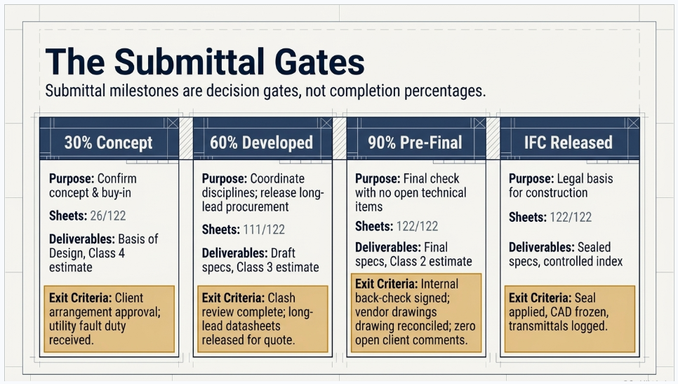
The percentage milestones are not measures of how much drafting is done. They are decision gates, each with a specific purpose, a specific deliverable list, and — most importantly — specific exit criteria. A milestone that is issued without meeting its exit criteria has not de-risked anything; it has only moved the risk downstream, where it costs more.
3.1 30% — Concept Design
The 30% submittal exists to answer one question: is this the right substation? Not is it detailed correctly, but is the arrangement, the equipment count, the voltage configuration and the footprint the right answer to the client's need. Getting a "yes" here is what makes the remaining seventy percent of the effort worth spending.
Typically 26 of the 122 electrical sheets are issued at 30%: the general sheets, the overall site plan and general arrangement, the governing one-line diagrams, a preliminary ground grid plan, the duct bank concept, the control house layout, and the major equipment schedule. Alongside them go the Basis of Design report, preliminary load flow and short circuit results, transformer sizing, and an AACE Class 4 cost estimate.
- Exit criteria: client has approved the arrangement and one-line configuration in writing; utility fault duty and interconnection requirements are received; soil resistivity testing is complete or scheduled; the Basis of Design is signed.
The most expensive mistake in substation engineering is skipping or rushing 30%. Every arrangement decision deferred past this gate gets re-litigated later, when foundations are dimensioned and steel is ordered.
3.2 60% — Developed Design
At 60% every sheet in the set exists and is developed. This is the coordination milestone — the point at which electrical, civil, structural and the client's operations group are working from the same geometry. It is also the gate that releases long-lead procurement, because equipment datasheets are mature enough to issue for quotation.
About 111 of 122 sheets are issued: all one-lines and three-lines, all AC and DC schematics, grounding, raceway, control house, SCADA and equipment details. Draft Division 26 and Division 33 specifications, a preliminary bill of materials and an AACE Class 3 estimate accompany them.
- Exit criteria: interdisciplinary clash review complete; grounding, cable sizing, DC battery and station service calculations at least preliminary and consistent with the drawings; long-lead datasheets released for quotation; all 30% comments formally dispositioned.
3.3 90% — Pre-Final Check Set
Ninety percent is the check set. Every sheet is complete, every calculation is signed, and the package has been through internal QA/QC with a documented back-check. Nothing at this gate should be a technical surprise; if it is, the 60% gate was not held properly.
The full 122-sheet set is issued, together with final specifications, a priced bill of materials, the complete signed calculation package and an AACE Class 2 estimate. Relay setting sheets are drafted here even though they are usually issued separately later.
- Exit criteria: internal back-check complete and signed; every study report final; all vendor certified drawings received and reconciled against the design; every open client comment closed. No comment may remain open at IFC.
3.4 IFC — Issued for Construction
IFC is not a completion percentage. It is a legal and professional act. The Engineer of Record applies a seal, the CAD files are frozen, the index becomes a controlled document, and the transmittal is signed and logged. From that moment, every change is a numbered revision or a bulletin — there is no such thing as quietly updating an IFC drawing.
This is the discipline that most distinguishes a mature design shop from an immature one. It is also the discipline that protects the client, because after IFC the drawing set becomes the definitive record of what was engineered, what was built against it, and where the responsibility for a deviation sits.
| Gate | Purpose | Sheets issued | Key non-drawing deliverables | Estimate class |
|---|---|---|---|---|
| 30% Concept | Confirm the concept and secure buy-in | 26 of 122 | Basis of Design; preliminary load flow, short circuit, transformer sizing, grounding | AACE Class 4 |
| 60% Developed | Coordinate disciplines; release long-lead procurement | 111 of 122 | Draft specifications; preliminary BOM; most calculations; equipment datasheets for quotation | AACE Class 3 |
| 90% Pre-Final | Final client review with no open technical items | 122 of 122 | Final specifications; priced BOM; complete signed calculation package; draft relay settings | AACE Class 2 |
| IFC Released | Release for construction under professional seal | 122 of 122 | Sealed specifications; construction BOM; controlled index; signed transmittals | Not applicable |
THE KEENTEL STANDARD
We publish the exit criteria for each gate in the Project Execution Plan at kickoff, and we do not issue a milestone that has not met them. If the utility fault duty has not arrived, the 30% goes out flagged as conditional rather than going out silently assuming a number.
Every client comment is logged, dispositioned and closed in a tracked comment register. We close 100% of comments before IFC — not as a target, as a precondition.
Our IFC release is a controlled event: seal applied, CAD frozen, index issued, transmittal signed and logged. Post-IFC changes are issued as numbered revisions with a bulletin describing what changed and why.
4. Anatomy of a substation electrical drawing set
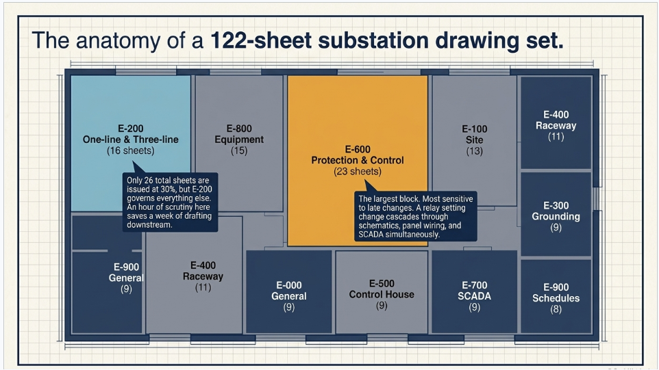
A well-structured electrical set is organized by series, and the series numbering carries meaning. A field engineer who knows the convention can find the DC trip circuit for a 138 kV breaker without opening the index, because it is in the E-600s. This is not cosmetic; on a project with 122 sheets, navigability is a safety and schedule issue.
The breakdown below is for a typical greenfield 138 kV / 13.8 kV distribution substation with one main power transformer, an air-insulated switchyard and a prefabricated control house. Scope drives the count — a gas-insulated station, a transmission switching station or a brownfield expansion will shift sheets between series — but the architecture holds.
| Series | Scope | Sheets | Representative sheets |
|---|---|---|---|
| E-000 | General | 9 | Cover and vicinity map; drawing index; general and construction notes; symbols and IEEE C37.2 device function numbers; design criteria and codes; clearance and working space requirements |
| E-100 | Site and arrangement | 13 | Overall site plan; electrical general arrangement plan and sections; foundation and steel interface; 138 kV and 13.8 kV bus arrangement; demolition; outage staging; yard lighting |
| E-200 | One-line and three-line | 16 | Overall one-line; 138 kV and 13.8 kV one-lines; transformer one-line; AC station service; 125 VDC; three-lines by position; metering and instrument transformer; protection one-line; ultimate build-out |
| E-300 | Grounding and lightning | 9 | Ground grid plan and equipment connections; grounding details and test wells; riser and bonding schedule; shield mast plan; rolling sphere analysis; fence grounding and step-touch details |
| E-400 | Raceway and cable | 11 | Duct bank plan, sections and profiles; cable trench; cable tray; yard conduit routing; manholes; power and control cable schedules; conduit schedule; pulling tension summary |
| E-500 | Control house | 9 | Floor plan and equipment layout; panel elevations; lighting and receptacles; HVAC power; grounding; cable entry and floor penetrations; fire detection; battery room layout and ventilation |
| E-600 | Protection and control | 23 | AC and DC schematics by position; breaker control and trip; transformer lockout (86T); bus differential (87B); breaker failure (50BF) and reclosing (79); annunciator; CT and PT circuits; relay panel wiring and elevations; junction box terminations |
| E-700 | SCADA and communications | 9 | System architecture; RTU panel wiring and I/O; DNP3 point list; fiber routing and splices; communications rack; substation LAN; revenue metering; GPS/IRIG-B time sync; cybersecurity boundary |
| E-800 | Equipment details | 15 | Breaker, disconnect switch, transformer, CT/CCVT and arrester installation; rigid and strain bus assemblies; station service transformer; battery and charger; metal-clad switchgear; cable terminations; oil containment interface |
| E-900 | Schedules and lists | 8 | Major equipment schedule; protective relay and device schedule; AC panelboard and DC distribution schedules; lighting schedule; nameplate schedule; electrical bill of materials; relay setting sheet index |
Two observations are worth drawing out of that table.
First, the E-600 protection and control series is the largest single block at 23 sheets — roughly one sheet in five. It is also the series most sensitive to late changes, because a relay setting change propagates into schematics, panel wiring, terminal blocks and the SCADA point list simultaneously. Sequencing the coordination and arc flash studies early is the single highest-leverage schedule decision on the electrical package.
Second, only 26 sheets are issued at 30%, but those 26 govern everything else. The one-line diagram alone constrains equipment ratings, protection philosophy, bus arrangement, grounding and the entire E-600 series. An hour of scrutiny on sheet E-201 is worth a week of drafting downstream.
5. The studies that drive the drawings
Drawings are the output. Studies are the reason the drawings say what they say. A substation electrical package normally rests on around twenty engineering studies, and the order in which they are executed determines the schedule far more than drafting capacity does.
The critical chain runs roughly like this. Utility source impedance and fault duty arrive from the interconnecting utility. That feeds the short circuit study, which sets breaker interrupting and momentary duties and therefore the equipment specification. Breaker and relay selection feeds the coordination study, which produces the settings. The settings feed the arc flash study, which produces incident energy, boundaries and the label schedule. Each link is a hard dependency: you cannot coordinate devices you have not selected, and you cannot compute incident energy from settings you do not have.
A parallel chain runs through grounding. Soil resistivity testing feeds the two-layer soil model, which feeds the IEEE Std 80 grid study, which sizes the conductor and sets grid geometry, step and touch potential and ground potential rise. If the soil testing has not been performed, the ground grid plan cannot leave preliminary status — and because the grid is installed before anything else in the yard, that becomes a construction-sequence problem quickly.
| Study | Governing standard | What it determines | First issued |
|---|---|---|---|
| Load flow and voltage regulation | IEEE 399 | Equipment loading and voltage profile under peak and contingency | 30% |
| Short circuit / fault duty | IEEE C37.010, ANSI C37.13 | Interrupting and momentary duties; breaker and bus selection | 30% |
| Transformer sizing and loading | IEEE C57.91 | MVA rating, thermal aging, emergency ratings | 30% |
| Substation grounding | IEEE Std 80, IEEE Std 81 | Grid conductor size and geometry; step and touch potential; GPR | 30% |
| Reliability and N-1 contingency | IEEE 493 | Single-contingency performance and outage impact | 30% |
| Protective device coordination | IEEE 242 | Relay, fuse and breaker settings; selectivity margins | 60% |
| Arc flash incident energy | IEEE 1584-2018, NFPA 70E | Incident energy, boundaries, PPE category, label schedule | 60% |
| Lightning / direct stroke shielding | IEEE Std 998 | Shield mast and wire placement; shielding failure rate | 60% |
| Insulation coordination | IEEE 1313, IEEE C62.22 | BIL selection; arrester MCOV and protective margins | 60% |
| Bus ampacity and short circuit forces | IEEE 605 | Conductor sizing, deflection, cantilever and fitting loads | 60% |
| Cable ampacity and derating | ICEA P-46-426, IEEE 835, NEC Art. 310 | Conductor sizing in duct bank, tray and direct buried | 60% |
| DC system and battery sizing | IEEE Std 485, IEEE 1375 | Duty cycle, cell count, charger sizing, DC voltage drop | 60% |
| AC station service load | NEC Art. 220, IEEE 666 | Auxiliary load list; station service transformer sizing | 60% |
| Motor starting | IEEE 399 | Voltage dip on starting the largest auxiliary motor | 60% |
| Harmonic and power quality | IEEE 519 | Distortion limits at the point of common coupling | 60% |
| Electromagnetic field (EMF) | IEEE C95.6, ICNIRP | Fence-line electric and magnetic field levels | 60% |
| Illumination / photometric | IES RP-8, RP-7 | Yard and control house illuminance and uniformity | 60% |
| Cable pulling tension | NEC Art. 300, ICEA | Pulling tension and sidewall bearing pressure limits | 90% |
| Transient recovery voltage | IEEE C37.011 | Breaker TRV capability for the application | 90% |
| Ferroresonance and switching transients | IEEE C57.105 | Overvoltage risk screening for switching configurations | 90% |
Note what sits in the 30% column. Five studies must be underway before the concept submittal, and three of them depend on data the engineer does not own — utility fault duty, soil resistivity, and the client's load forecast. Chasing that data is a project-management task that starts on day one, not an engineering task that starts when the drafter needs a number.
WHAT KEENTEL DELIVERS
Full power system study capability: load flow, short circuit, protective device coordination, arc flash and incident energy, motor starting, harmonics and power quality, and reliability analysis — modelled in ETAP, SKM PowerTools and EasyPower.
Substation grounding to IEEE Std 80 including two-layer soil modelling and step/touch potential analysis, lightning shielding to IEEE Std 998, insulation coordination, bus and cable ampacity, and DC battery sizing to IEEE Std 485.
Stamped study reports and relay setting packages, issued as standalone deliverables that a client's protection group can audit line by line — not as an appendix nobody reads.
Arc flash label schedules delivered ready for field application, with the incident energy basis traceable to the coordination study that produced it.
6. The folder structure that holds it together
Below is the top level of the structure we instantiate on every substation project. The principle is that a document's location tells you its status — received or produced, current or superseded, which milestone it belongs to — without opening it.
| Top-level folder | What it holds | Why it is separate |
|---|---|---|
| 00_Project_Administration | Contract and scope, fee, schedule, meeting minutes, correspondence, transmittal register, QA/QC records, Project Execution Plan | Commercial and control records stay clear of technical content |
| 01_Reference_and_Input_Data | Client standards, as-builts, survey and geotechnical, utility fault duty, site photos, permits, existing nameplate data | Read-only. Nothing received is ever edited in place |
| 02_Design_Calculations | Fourteen calculation packages from load flow through conduit fill, plus the calculation index and log | One signed PDF per calculation, individually revisable |
| 03_Engineering_Studies_and_Reports | Basis of Design, power system study, grounding study, arc flash study, relay setting report, native model files | Studies are standalone stamped deliverables, not drawing attachments |
| 04_Drawings | 30%, 60%, 90%, IFC and Superseded — each with its own PDF, CAD, index, specification, BOM, transmittal and comment-response subfolders | Milestone is the primary organizing principle; sets cannot be confused |
| 05_Technical_Specifications | Division 26 electrical, Division 33 utilities, Divisions 27/28 communications and safety | Working spec files, separate from the issued copies inside each milestone |
| 06_Vendor_and_Manufacturer_Data | Ten equipment streams by tag, plus the submittal review log | Vendor data has its own review cycle and approval status |
| 07_Procurement_Support | Requisitions and datasheets, bid tabulations, purchase orders, long-lead tracker | Procurement runs on a different clock than design |
| 08_Construction_Support | RFI log, field change notices and SK sketches, site observation reports, submittal reviews, punch list | Post-IFC engineering support, cleanly separated from design |
| 09_Commissioning_and_Testing | Commissioning plan, FAT and SAT reports, as-left relay setting files, energization and switching orders | Test records are the bridge from construction to operation |
| 10_As_Built_Record_Drawings | Contractor redlines, updated CAD, sealed as-built PDFs, final index | The record set the owner will use for the next twenty years |
| 11_Project_Closeout_and_Archive | Final deliverable package, O&M manuals, lessons learned, zipped native file archive | Handover is a deliverable, not an afterthought |
7. Six ways substation packages go wrong
Each of the following is a failure we have been brought in to fix on someone else's project. In every case the underlying cause was structural, and in every case a specific control would have prevented it.
7.1 The 30% gate gets compressed
Under schedule pressure, the concept submittal is issued without a signed Basis of Design and without written arrangement approval. Every arrangement question then reopens at 60%, when foundations are dimensioned and steel is being ordered. Rework at that point costs five to ten times what it would have cost at concept.
- Control: written arrangement and one-line approval is a hard exit criterion for 30%. No approval, no 60% start.
7.2 Drawings run ahead of the calculations that govern them
A schematic gets drafted with an assumed CT ratio because the coordination study is not finished. The assumption is never revisited. It survives into IFC and is discovered during functional testing.
- Control: the drawing register carries an explicit dependency for each sheet, and any value taken from an unissued calculation is flagged as a hold on the sheet — visibly, in a hold list, not in a drafter's memory.
7.3 Vendor data arrives after the drawings that depend on it
Certified transformer or switchgear drawings arrive at 85% design, and the bushing arrangement, control cabinet terminal numbering or dimensions differ from the design assumptions. The E-600 and E-800 series need rework at exactly the wrong moment.
- Control: long-lead datasheets are released for quotation at 60%, and the design freezes only against certified vendor drawings — with the reconciliation itself a documented 90% exit criterion.
7.4 Comments are answered but never closed
A client marks up the 60% set. Some comments are addressed, some are addressed differently than intended, and a handful are never dispositioned. Six months later the same comment appears as a construction RFI.
- Control: a tracked comment register with a disposition and a responder for every single comment, reviewed with the client before the next gate opens.
7.5 Revision control breaks at IFC
Post-IFC changes get issued as "revised" PDFs by email rather than as numbered revisions with transmittals. Within weeks, three parties hold three different versions of the same sheet and none of them is identifiable as current.
- Control: IFC freezes the CAD and the index. Every subsequent change is a numbered revision with a bulletin, a signed transmittal and a superseded copy moved and stamped.
7.6 The as-built never happens
Construction finishes, the team demobilizes, and the contractor redlines sit in a box. The owner operates for a decade against an IFC set that no longer matches the station — and the next expansion project starts by paying an engineer to walk down and re-document what is there.
- Control:
as-built incorporation is a contracted deliverable with its own folder, its own budget line and its own seal — not a courtesy at the end of the job.
8. Working with Keentel Engineering
Keentel Engineering provides electrical power engineering design and studies services for utilities, industrial owners, developers and EPC partners. We take substation and switchyard packages from concept through IFC, construction support and as-built — and we do it inside the deliverable structure described in this article, on every project, without exception.
Design services
- Substation and switchyard design, 4.16 kV through 345 kV, AIS and GIS, greenfield and brownfield expansion
- Complete E-series drawing packages: arrangement, bus design, one-line and three-line development, protection and control schematics, grounding and lightning protection, raceway and cable systems, control house electrical, SCADA and communications equipment detailing and schedules
- Industrial and facility power distribution, medium-voltage switchgear and MCC design, standby and emergency power systems
- Technical specifications, Division 26 and Division 33, and equipment datasheets issued for quotation
Studies and analysis
- Load flow, short circuit, protective device coordination, arc flash and incident energy, motor starting, harmonics and power quality, and reliability analysis in ETAP, SKM PowerTools and EasyPower
- Substation grounding to IEEE Std 80 with two-layer soil modelling; lightning shielding to IEEE Std 998; insulation coordination; bus and cable ampacity; DC battery sizing to IEEE Std 485
- Arc flash label schedules and NFPA 70E compliance packages, delivered ready for field application
- Relay setting calculations, setting files and functional test procedures
Project delivery
- Owner's engineer and design review services, including independent review of a third party's 30/60/90 submittals
- Construction support: RFI response, field change notices, site observation and submittal review
- Commissioning support, FAT and SAT witnessing, energization planning and as-built record drawings
WHAT YOU GET ON DAY ONE
A Project Execution Plan with published exit criteria for every gate — so "60% complete" means the same thing to you as it does to us.
The full project folder structure, instantiated and shared, so your document control team is never guessing where something lives.
A live drawing register listing every sheet, its file names, its status at each milestone and its current revision — updated continuously, not reconstructed before each submittal.
A named Engineer of Record who holds the seal from kickoff to as-built.
Have a substation package that needs to be under control?
Whether you are scoping a new station, holding a 60% set that will not stop moving, or preparing to issue for construction and wanting a second set of eyes before the seal goes on — talk to us. Initial scoping conversations are complimentary, and we will tell you plainly whether your package is ready for the next gate.

About the Author:
Sandip "Sonny" R. Patel, P.E.
IEEE Senior Member · Founder & CEO, Keentel Engineering
In 1995, Sonny Patel earned his Electrical Engineering degree from the University of Illinois. But degrees don't build legacies — action does.
For three decades, he has worked the power industry from every side of the table: 16 years as a utility engineer at Exelon/Commonwealth Edison; generation leadership across hydroelectric, industrial steam turbine, and a 9 GW renewable fleet; NERC Regional Entity Senior Compliance Engineer and Audit Team Lead, auditing some of the nation's largest utilities; and testing and commissioning lead on equipment up to 765 kV — the very top of the North American grid.Utility. Generator. Regulator. Consultant. Few engineers have seen all four seats. Fewer still have sat in them.
His experience spans nuclear, hydro, conventional generation, renewables, oil and gas, mining — and today's data centers, where he is authoring a three-book series on data center design. He is a Licensed Professional Engineer in six states and a Licensed Electrical Contractor in Florida (Unlimited EC) — he doesn't just design the work; he's qualified to stand behind its execution.Today, as Founder and CEO of Keentel Engineering, Sonny leads a nationwide team of engineers delivering substation design, power system studies, NERC compliance, and commissioning — done right, coast to coast.Three decades. Every side of the table. One standard: accountable engineering.
Services

Let's Discuss Your Project
Let's book a call to discuss your electrical engineering project that we can help you with.
About the Author:
Sandip "Sonny" R. Patel, P.E.
IEEE Senior Member · Founder & CEO, Keentel Engineering
In 1995, Sonny Patel earned his Electrical Engineering degree from the University of Illinois. But degrees don't build legacies — action does.
For three decades, he has worked the power industry from every side of the table: 16 years as a utility engineer at Exelon/Commonwealth Edison; generation leadership across hydroelectric, industrial steam turbine, and a 9 GW renewable fleet; NERC Regional Entity Senior Compliance Engineer and Audit Team Lead, auditing some of the nation's largest utilities; and testing and commissioning lead on equipment up to 765 kV — the very top of the North American grid.
Utility. Generator. Regulator. Consultant. Few engineers have seen all four seats. Fewer still have sat in them.
His experience spans nuclear, hydro, conventional generation, renewables, oil and gas, mining — and today's data centers, where he is authoring a three-book series on data center design. He is a Licensed Professional Engineer in six states and a Licensed Electrical Contractor in Florida (Unlimited EC) — he doesn't just design the work; he's qualified to stand behind its execution.
Today, as Founder and CEO of Keentel Engineering, Sonny leads a nationwide team of engineers delivering substation design, power system studies, NERC compliance, and commissioning — done right, coast to coast.Three decades. Every side of the table. One standard: accountable engineering.
Leave a Comment
Thank you for contacting us.
We will get back to you as soon as possible.
We will get back to you as soon as possible.
Oops, there was an error sending your message.
Please try again later.
Please try again later.
Related Posts

By SANDIP R PATEL
•
October 13, 2026
Plan data center capacity with land screening, MW-per-acre estimates, grid power availability and interconnection feasibility studies from Keentel Engineering.

By SANDIP R PATEL
•
October 11, 2026
Learn which fault produces the highest current at a bus, why SLG faults can exceed three-phase faults, and how symmetrical components determine fault duty.

By SANDIP R PATEL
•
October 11, 2026
Learn why zero-sequence current pulsates in the dq0 frame, how Park's transformation works, and how inverter controls handle unbalance and ground faults.

By SANDIP R PATEL
•
October 11, 2026
Explore grid inertia, RoCoF and frequency response, with swing equation calculations, frequency nadir analysis and US power system simulation examples.

By SANDIP R PATEL
•
October 11, 2026
Learn transient stability analysis, swing equation, equal-area criterion and critical clearing time with a 345 kV worked example and NERC TPL-001 guidance.

By SANDIP R PATEL
•
October 11, 2026
Learn why inverter controls become unstable in weak grids, how PLL bandwidth and SCR affect stability, and how PSCAD EMT studies identify and mitigate oscillations.

By SANDIP R PATEL
•
October 11, 2026
Learn how STATCOMs improve voltage stability and prevent FIDVR. Explore reactive power sizing, delayed fault clearing, NERC criteria and 138 kV simulation results.

By SANDIP R PATEL
•
October 10, 2026
Learn BESS DC sizing with power, energy, current and C-rate calculations, battery losses, degradation and a 100 MW/400 MWh utility-scale example.

By SANDIP R PATEL
•
October 10, 2026
Learn how BESS ROI is calculated using peak shaving, energy arbitrage, power quality and battery storage economics, with a practical 5 MW/10 MWh example.





