
A Coordinated Electric System Interconnection Review—the utility’s deep-dive on technical and cost impacts of your project.
Challenge: Frequent false tripping using conventional electromechanical relays
Solution: SEL-487E integration with multi-terminal differential protection and dynamic inrush restraint
Result: 90% reduction in false trips, saving over $250,000 in downtime
ERCOT enforces all of the above through simulation, which means your model is your compliance case. The bar is now high:
- Whole-facility scope. The model must represent everything the IT load, the UPS and power conversion, the cooling plant, the protection and control systems in formats compatible with ERCOT's study platforms (PSS/E, PSCAD, TSAT).
- Real control loops, not approximations. Generic textbook representations are unacceptable. The model must capture the actual inner control behavior of your power electronics.
- Hardware-validated converter models. For electronic loads, the PSCAD model must be benchmarked against actual hardware testing including voltage ride-through and subsynchronous response. A model assembled from standard PSCAD library blocks fails by definition, because a generic block has never been tested against your vendor's hardware. The good news: validation is a hardware-type test, so results for a given converter product are reusable across every facility that uses it.
- Format migration. Facilities that previously submitted the older composite load model (CMLD) format must transition to EPRI's PERC1 format.
- Three checkpoints. Models are reviewed before the stability study begins (no model, no study), before each quarterly stability assessment, and for electronic loads one final time before energization, when you must submit as-built models with a documented comparison against the previously studied data and a sworn attestation that the model matches actual field settings. ERCOT's review takes 10 business days, extendable by 20 put it on your critical path.
- A living obligation. Change your technology, controls, or relay settings in a way that affects ride-through including converting a crypto mining site to an AI data center — and you've triggered a new interconnection study, even if your megawatts don't change.
| Parameter | Detail |
|---|---|
| System | 230 kV / 138 kV transmission corridors, wind and wet-snow icing exposure |
| Data basis | 15 years of minute-resolution forced-outage records + regional weather observations |
| Core methods | Event grouping, MVA performance curves, time-to-95%-restore, area outage rate curves, fragility modeling, rerun-history benefits, exceedance and log-domain risk metrics |
| Headline result | ≈85% of maximum resilience benefit at 60% of original capital; worst-event restoration window cut from 11 days to 5 in rerun-history terms |
| Decision supported | Capital portfolio selection; resilience plan filing; post-investment verification framework |
| System / Topic | Governing Standard(s) | What It Controls |
|---|---|---|
| Overall plant electrical distribution | IEEE 141 (Red Book); IEEE 666 | Distribution architecture, voltage selection, design of generating station auxiliary service systems |
| Power system studies | IEEE 399 (Brown Book); IEEE 551 | Load flow, symmetrical/asymmetrical short circuit, motor starting methodologies down to the lowest LV panelboard |
| Protection & coordination | IEEE 242 (Buff Book); IEEE 3004.5; IEEE C37 series | Generator relaying (21, 59N, 87G), time-current coordination, selective clearing between LV and MV tiers |
| GSU / UAT / SST transformers | IEEE C57.12.00 and C57 family | Transformer ratings, impedance, testing, loading |
| HV switchyard breakers | IEEE C37.06 | AC high-voltage circuit breaker preferred ratings |
| MV switchgear (13.8 kV) | IEEE C37.20.2; IEEE C37.20.7 | Metal-clad construction, compartmentalization, vacuum breakers; arc-resistant design with plenum venting |
| MV cable | UL 1072; ICEA S-93-639 (NEMA WC 74) | Type MV-105 shielded cable, 133% insulation level for HRG systems |
| LV switchgear (480 V) | IEEE C37.13; UL 1558 | Metal-enclosed LV power circuit breaker switchgear to 635 V, draw-out ACBs with electronic trip units |
| Motor control centers | UL 845; NEMA ICS 18 | LV-MCC construction, MCCB/MCP protection for motors under ~200 HP |
| Motors | NEMA MG-1 | Motor performance, starting characteristics, service factors |
| DC & battery systems | IEEE 485; IEEE 946 | Lead-acid battery sizing (125/250 VDC), DC auxiliary system design |
| Grounding | IEEE 80; IEEE 142 (Green Book) | Ground grid step/touch potential limits; system grounding including high-resistance grounding |
| Lightning protection | IEEE 998 | Direct-stroke shielding of switchyard and outdoor generator structures |
| Arc flash & electrical safety | IEEE 1584; NFPA 70E | Incident energy calculation; worker safety boundaries and PPE |
| Fire protection | NFPA 850 | Fire protection and risk management for combustion turbine generating plants |
| Installation code | NEC (NFPA 70); NESC | Wiring methods inside the plant fence; overhead/outdoor clearances at the switchyard |
| Interconnection & compliance | FERC LGIP; NERC MOD-025/026/027, PRC-019/024/029, FAC-008 | Interconnection process, model validation, protection/ride-through coordination, facility ratings |
| IFC / Construction Deliverable | Purpose |
|---|---|
| Stamped IFC packages | Legal basis for construction; P.E. responsible charge |
| Final relay settings & TCCs | Protection as-installed matches the coordination study |
| Calculation archive | Owner records; NERC audit evidence trail |
| Commissioning procedures | Safe, sequenced energization; MOD field testing |
| Construction support | RFIs, field changes, FAT/SAT witness |
| As-builts & model handoff | Operating baseline; future study currency |
| Metric | Outcome |
|---|---|
| Defects found pre-occupancy | Three topology defects and one settings-mismatch family corrected before load migration; the shared-switchboard defect alone would have invalidated the concurrently-maintainable claim on day one |
| IST findings | Fourteen additional discrepancies surfaced under scenario testing (control logic, alarm mapping, one generator sequencing fault) — all closed before handover instead of during operations |
| Black-building test | Passed on second execution; the first attempt exposed the generator sequencing fault under true block load, exactly the failure the compressed plan would never have found |
| Handover quality | Operations team certified on the actual failure scenarios; corrected EOPs and settings documentation delivered as controlled documents |
| Business outcome | Occupancy proceeded three weeks behind the original date — against an independent estimate that the uncorrected sequencing fault carried a high probability of a full facility outage within the first year |
Part 2 — Frequently Asked Questions: Large Load Interconnection
An electric grid must remain in continuous balance — generation onto the grid must equal consumption from it at every instant. PJM achieves this balance, and prices it, through a layered market architecture. Each layer operates on a different time horizon, and each one touches project economics differently.
| Domain | Key Standards / Codes | What They Govern |
|---|---|---|
| Fire safety | NFPA 855; UL 9540 / UL 9540A | Installation requirements, separation, gas management; system safety listing and thermal-runaway fire testing |
| Grid interconnection | IEEE 1547 (distribution); IEEE 2800 (transmission IBRs) | Ride-through, reactive capability, power quality, and performance at the point of interconnection |
| Power quality | IEEE 519 | Harmonic distortion limits at the PCC |
| Protection & grounding | IEEE 80 / 81 / 142; C37 series | Grounding system design and testing; protective relaying |
| Reliability compliance | NERC standards (incl. PRC ride-through requirements) | Registered-entity obligations for grid-connected storage |
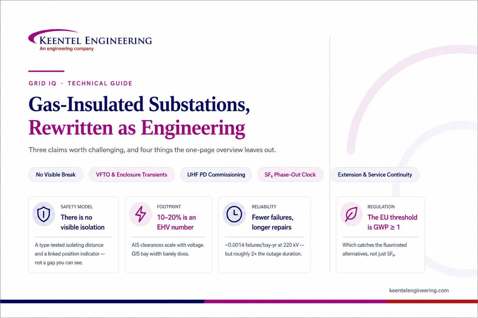
Gas-Insulated Substations, Rewritten as Engineering: Three Claims Worth Challenging and Four Things the Overview Leaves Out
Aug 16, 2026 | Blog
A Keentel Engineering Grid IQ technical guide for utility planners, substation engineers, owner's engineers, and industrial and data-center power teams
Introduction: A Good Diagram With Three Problems
The standard one-page GIS explainer is genuinely useful. It shows the bus, the circuit breaker, the disconnector, the earthing switch, the CT and the VT, all sealed inside a metal enclosure filled with SF₆. It lists the advantages — compact, high reliability, low maintenance, enhanced safety, suitable for harsh environments — and the applications: urban substations, generation plants, refineries, offshore, rail, and increasingly data centers.
Almost all of that is correct. Three things are not, and they matter.
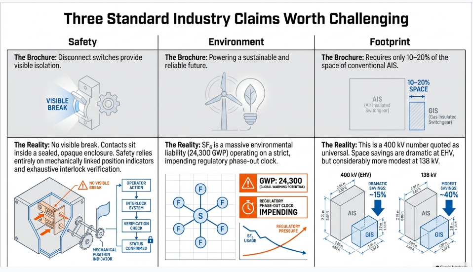
"Disconnect switch — provides visible isolation." This is the most consequential error in circulation. In a gas-insulated substation there is no visible break. The disconnector's contacts sit inside a sealed aluminium enclosure filled with opaque gas. You cannot see them, and IEC does not require you to. Safety derives instead from a type-tested isolating distance combined with a position indicator that is mechanically linked to the moving contact — a fundamentally different assurance model from the one most US switching and clearance rules were written around. Getting this wrong is not a semantic issue; it is a personnel-safety procedure issue.
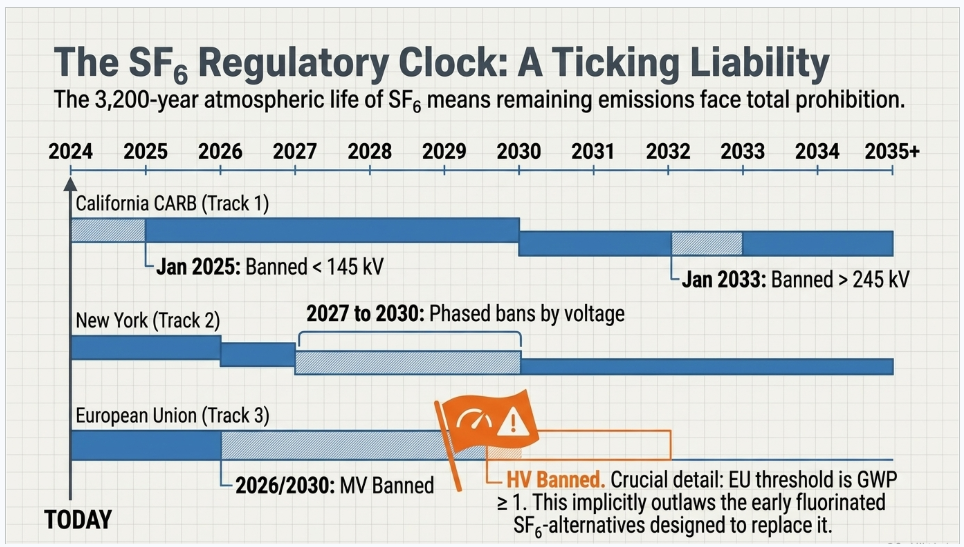
"GIS — powering a reliable and sustainable future." SF₆ is the most potent greenhouse gas the IPCC evaluates, with a 100-year global warming potential in the range of 22,800 to 24,300 depending on which assessment report you cite, and an atmospheric lifetime commonly given as 3,200 years. In the European Union, new SF₆ switchgear is already prohibited at medium voltage, and prohibitions bite at transmission voltage in 2028 and 2032 — with a threshold set at GWP ≥ 1, which catches the fluorinated alternatives that were supposed to replace it. In California, acquisition of new SF₆ gas-insulated equipment below 145 kV has been prohibited since January 2025. GIS is an excellent technology; SF₆ is a liability with a schedule attached.
"Requires only 10–20% of the space of conventional AIS." This is a 400 kV number quoted as though it were universal. AIS clearances scale with voltage; GIS bay width barely does. The saving is dramatic at EHV and considerably more modest at 72.5 to 145 kV, and repeating the EHV figure on a 138 kV project will produce a land budget that does not survive first contact with a general arrangement drawing.
And then there is what the overview does not mention at all: very fast transient overvoltages, enclosure circulating currents, what an internal arc does to the gas and to the people nearby, and the fact that a GIS has a commissioning regime that has almost nothing in common with an AIS yard.
This guide covers all of it.
Part 1 — What GIS Actually Is
A gas-insulated substation is a coaxial system. The current-carrying conductor runs down the centre of a grounded aluminium tube, supported at intervals by cast epoxy insulators (spacers), with pressurized SF₆ filling the annulus.
That geometry is why GIS is compact. In air-insulated switchgear the insulating medium is the atmosphere, and the phase-to-earth and phase-to-phase clearances required grow roughly linearly with voltage — which is why a 400 kV AIS bay is enormous and a 400 kV GIS bay is a few metres wide. SF₆ at typical operating pressure has roughly two to three times the dielectric strength of air, and about a hundred times better arc-quenching capability, which is what makes the interrupter compact as well as the bus.
But the number that actually governs the design is much lower than the raw strength figure suggests. Reliable service design stress in SF₆ is on the order of 5 kV/mm RMS at power frequency and about 15 kV/mm peak for lightning impulse, at typical operating pressures of 400–600 kPa absolute. The reason for the derating is the single most important physical property of SF₆ for a GIS engineer to understand:
SF₆ is exceptionally sensitive to local field enhancement. Its dielectric strength collapses in a non-uniform field far more sharply than air's does. A sharp protrusion, a burr left by machining, or — most commonly — a loose conductive particle rattling around inside the enclosure will reduce the withstand capability of the gap dramatically.
Everything else in GIS engineering follows from that one sentence. It is why the enclosures are assembled in clean-room-like conditions, why every compartment has a particle trap, why the on-site test begins with a conditioning voltage sequence rather than going straight to the withstand level, and why the commissioning partial discharge test is calibrated against a moving metal particle rather than a void.
Part 2 — The Components, Corrected
2.1 Bus bar and enclosure — and the choice most specifications skip
The infographic describes the bus as the "main current-carrying conductor… enclosed in SF₆ gas for insulation." True, but incomplete in a way that has real cost consequences.
There are two architectures. In a three-phase (common) enclosure, all three conductors share one tube; the phases' magnetic fields largely cancel, so induced enclosure current is inherently small, and the assembly is cheaper and more compact. In a single-phase enclosure, each phase has its own tube; a phase-to-phase fault inside the enclosure becomes essentially impossible, which is why single-phase enclosure dominates above about 245 kV.
Three-phase enclosure is standard at 72.5–145 kV, mixed in the 145–245 kV band, and rare above that. The choice affects footprint, fault-mode assumptions, gas volume per compartment, and — as Part 3 explains — the enclosure bonding design.
2.2 Circuit breaker
The GIS circuit breaker interrupts using SF₆ in a puffer or self-blast interrupter, and the standards that govern it are the same as for any other HV breaker: IEC 62271-100 (current edition 3.0:2021, consolidated 3.1 with Amendment 1 in August 2024).
What a specification should state, and frequently does not, are the class designations:
- E1 / E2 — electrical endurance. E2 breakers are designed not to require maintenance of the interrupting parts during expected operating life.
- M1 / M2 — mechanical endurance.
- C1 / C2 — capacitive current switching, defined by restrike probability. C2 means very low probability of restrike, and it is what you want for capacitor bank, cable and unloaded line switching.
- S1 / S2 — S1 for a breaker in a cable system, S2 for a line system or a cable system connected directly to an overhead line.
Writing "IEC 62271-100 compliant" procures nothing in particular. Writing "E2, M2, C2, S2" procures a specific machine.
2.3 Disconnector — where the infographic is wrong twice
Error one: there is no visible isolation.
IEC 62271-102 (current edition 2.0:2018 with Amendment 1:2022) handles disconnectors and earthing switches, and its Edition 2.0 changelog is explicit that it modified "the way to comply with the requirements of the isolating distance of disconnectors" and modified "design and construction requirements for position-indicating devices, aligning the requirements for position indication and signalling." Clause 6.104.3 carries the design and construction requirements for position indication and signalling; Clause 7.105 requires verification tests.
The concept is this: safety comes from a type-tested isolating distance — a gap proven to withstand a specified voltage across the open contacts — combined with a position indicator mechanically linked to the moving contact, not to the operating mechanism or to a limit switch that a broken linkage could defeat. The indicator must be incapable of showing "open" when the contact is not open. That is the substitute for the visible break.
An inspection window is permitted but not required. IEC 62271-203 acknowledges the case where a window exists and requires that dielectric testing be performed with "an earthed metal foil covering the accessible side" — i.e. the standard treats a viewport as a dielectric weak point to be shielded during test, not as a safety feature to be encouraged. Windows are also, as Part 3 explains, one of the apertures through which transient enclosure voltage escapes onto the outside of the enclosure.
Why this matters operationally. Most US utility switching, clearance and tagging procedures were written for AIS, where the operator physically sees an open air gap before applying protective grounds. GIS replaces that with a position indicator, an interlock scheme, and an integral earthing switch. Before a GIS is energized, three things need to be true:
- The utility's switching orders, clearance procedures and tagging rules have been reviewed and updated for a no-visible-break environment.
- The interlocking — mechanical and electrical — has been fully verified during commissioning, every permitted and prohibited combination, not sampled.
- Operator training reflects the change.
Item 2 is one of the highest-value line items in a GIS commissioning scope and one of the first things truncated under schedule pressure.
Error two: "operated only under no-load condition."
Directionally right, dangerously incomplete. A GIS disconnector is not a load-break device, but it does switch something every time it operates: the capacitance of the bus section it is isolating. IEC 62271-102 Clause 5.108 establishes a rated bus-transfer current and rated bus-transfer voltage as declared values with an associated test duty, and Edition 2.0 added a classification of bus-charging switching capability. More importantly, that switching operation is the origin of the single most GIS-specific transient phenomenon in the substation — covered in Part 3.
2.4 Earthing switch — and the classes nobody specifies
The infographic's description ("grounds isolated equipment, protects maintenance personnel, eliminates trapped charges") is correct. What it omits is that earthing switches come in classes, and the difference is safety-critical.
Per IEC 62271-102, short-circuit making capacity classes:
- E0 — not capable of making short-circuit current
- E1 — one short-circuit making operation at rated short-circuit making current
- E2 — two short-circuit making operations at rated short-circuit making current
And mechanical endurance classes M0 (100 operations), M1 (1,000 operations — a class newly added for earthing switches in Edition 2.0) and M2 (10,000 operations).
The distinction that matters: a fast-acting (high-speed) earthing switch rated E1 or E2 can be closed onto an energized circuit without destroying itself. An E0 maintenance earthing switch cannot. On a circuit that could be inadvertently energized, or where induced voltage from a parallel circuit is significant, specifying E0 to save money is a decision that will eventually be examined by an investigator.
2.5 Instrument transformers — and the quiet revolution
The infographic shows conventional CTs and VTs. That is still the mainstream, but it is changing, and the change is one of the main routes by which GIS cost is coming down.
Conventional inductive VTs and CTs inside a GIS are large, heavy, gas-filled and expensive, and a VT compartment is a significant source of failure — the independent GIS operational study cited in Part 5 found failures concentrated in circuit breakers, disconnectors and voltage transformers. Low-power instrument transformers (LPITs) — Rogowski coils for current and capacitive or optical dividers for voltage — are substantially smaller, have no ferroresonance behaviour, no saturation, and no risk of an open-circuited secondary. The published economics of GIS cost reduction attribute a meaningful share of it to replacing electromagnetic instrument transformers with optical sensors and Rogowski coils.
The trade is that LPITs deliver a low-energy analogue or digital output rather than 1 A or 5 A, so the protection and metering scheme must be designed for them from the start — typically an IEC 61850-9-2 process bus architecture. That is a system-level decision made at concept stage, not a component substitution made at procurement.
2.6 Combined disconnector/earthing switch
The infographic is right that this is a genuine space and component saving, and it is standard practice. The engineering caveat is interlocking: a three-position device (closed / open / earthed) makes some unsafe combinations mechanically impossible, which is a real safety gain, but it also means the position indication and the interlock logic carry more weight than they would with separate devices. Verify both exhaustively at commissioning.
2.7 The components not on the diagram
Every GIS compartment also contains, and every specification should address:
- Spacers — cast epoxy insulators supporting the conductor and, at gas barriers, separating compartments. The gas-barrier spacer is a pressure-retaining component.
- Particle traps — low-field recesses adjacent to spacers designed so a hopping particle falls in and cannot escape.
- Adsorbers (molecular sieve) — dual-function: controlling moisture, and scavenging reactive decomposition products. This is why an adsorber in a heavily arced compartment must be handled as contaminated waste.
- Density monitors, per compartment, with alarm and lockout stages. Density, not pressure — the whole point is temperature compensation.
- Rupture discs / pressure relief devices, per compartment, aimed so the discharge plume does not impinge on operator positions or adjacent bays.
- Enclosure bonding connections — see Part 3.
Part 3 — The Four Things the Overview Leaves Out
3.1 Very fast transient overvoltages
The mechanism. A GIS disconnector moves slowly, because it is not designed to interrupt load current. Switching a short bus section leaves trapped charge on the isolated side. As the contacts travel, the gap breaks down repeatedly — a train of pre-strikes and re-strikes. Breakdown in compressed SF₆ is extremely fast, so each strike injects a step wave into what is, electrically, a low-loss coaxial transmission line. The wave reflects off every discontinuity — open disconnectors, bushings, T-junctions, transformer terminals — and builds standing waves.
The numbers, which vary by source and should be presented as ranges:
| Quantity | Typical range |
|---|---|
| Rise time | 2–20 ns |
| Frequency content | 30 kHz – 100 MHz, with dominant oscillation in the MHz range |
| Magnitude | 1.4–2.0 p.u. measured typical; theoretical maximum around 3.0 p.u. |
| Trapped charge voltage | −0.3 to −1.0 p.u., design-specific, driven by contact speed |
Why it matters. Three consequences, in descending order of how expensive they are:
A nanosecond front does not distribute linearly across a transformer winding. It concentrates on the first few turns and discs of the line-end coil, producing inter-turn stresses far above what the winding's BIL rating implies. This is the reason a direct transformer-to-GIS connection needs a VFTO study. The relevant standard, IEC 62271-211, went to a new Edition 2.0 in September 2024 — worth noting, because it superseded a 2014 first edition and added type and routine test requirements plus new safety and environmental clauses.
Transient enclosure voltage (TEV) — the subject of the next section.
EMI into secondary systems. The transient field couples into control cables, instrument transformer secondaries and IEDs. This is why GIS secondary cabling discipline — routing, shielding, shield bonding at both ends, segregation from primary enclosures — is materially more demanding than in an AIS yard.
Mitigation. Damping resistors fitted in series with or parallel to the disconnector main contacts are the established solution, with 110 Ω used in Italian practice and 500 Ω in China, Japan and Korea. High-frequency resonators and nanocrystalline rings on the conductor each offer roughly 20% damping. But the cheapest mitigation is specification: choose disconnectors with inherently low trapped-charge-voltage characteristics (faster contact travel), and require the VFTO study before the arrangement is frozen rather than after.
Note one currency item: IEEE C37.122.1-2014, which explicitly listed very fast transients in its scope, was moved to Inactive-Reserved on 27 March 2025. Its content was largely absorbed into IEEE C37.122-2021 and C37.122.7-2021. A 2026 contract that specifies "per IEEE C37.122.1" is specifying a withdrawn document.
3.2 Enclosure earthing and circulating currents — the opposite of cable practice
This is where an engineer trained on HV cable systems can get GIS badly wrong.
The physics. In a single-phase-enclosed GIS the enclosure is a coaxial return conductor. The centre conductor's magnetic field induces a longitudinal EMF in the enclosure. If the enclosure is bonded at both ends, a current flows in it that nearly cancels the external field. Published figures put the enclosure return current at up to 90% of the operating current in normal service, and similarly high proportions of fault current during a fault, with measured values in one case running 50–85% of a 2,000 A primary current.
Why both-end bonding, when cable sheaths use single-point bonding. For HV cable, single-point bonding eliminates sheath circulating losses and is standard practice. For GIS it is wrong, for three reasons:
- Without a return path, the induced EMF appears as a standing voltage on the enclosure — a touch hazard on a structure personnel walk past continuously, at head height, in an enclosed building.
- The circulating current is exactly what cancels the external magnetic field, keeping stray field in the GIS hall low and protecting secondary equipment.
- The bonded enclosure is the fault-current return path, giving low-impedance clearance and limiting ground potential rise.
So GIS uses multipoint bonding — short, low-impedance interconnections between enclosures and the ground grid at close intervals, on the order of every ten metres, over a high-density earth mat under the hall. Contrast that with AIS practice, where a perimeter loop plus equipment risers is often sufficient.
Transient enclosure voltage. When very fast transients reach an enclosure discontinuity they couple onto the outside of the enclosure and escape through apertures — SF₆-to-air bushings, gas-to-cable terminations, non-metallic viewing ports, insulated flanges. Published magnitudes vary widely; a documented field case gives roughly 45 kV, about 26% of the voltage input to the bushing, on a 525 kV installation, and the literature range commonly quoted is 10–100 kV with durations up to about 10 µs. Simulation values an order of magnitude higher circulate, and should be treated as artefacts of idealized grounding models.
The practical consequences are not electrocution — the documented outcome is "no injuries reported but possible dangerous reactions," meaning startle-reaction falls — but destruction of electronic components in secondary equipment, and sparking in air between grounded parts where multipoint bonding is inadequate.
Touch potential inside a GIS hall is a greater hazard than step potential, which inverts the usual AIS assumption, and it requires dedicated grounding analysis rather than a standard grid calculation.
One currency note worth flagging to anyone writing a grounding specification: IEEE Std 80-2013 was moved to Inactive-Reserved on 21 March 2024, with a revision project active but unpublished. A great many US GIS grounding specifications cite it as current.
3.3 Internal arc, and what the gas does to people afterwards
IEC 62271-203 requires compartments to be fitted with pressure relief devices to limit the external effects of an internal arc, with performance criteria based on arc duration and short-circuit current, and Annex B of the current Edition 3.0 (2022) containing the methods for testing under arcing due to internal fault. Filling pressure relief valves must prevent gas pressure exceeding 10% above design pressure.
The two failure modes the design must prevent are enclosure burn-through — the arc root melting the aluminium wall and ejecting molten metal and hot gas into an occupied building — and enclosure rupture from pressure rise. The rupture disc is sized to relieve before the enclosure yields, and aimed away from operator positions.
What the arc does to the gas is the part that is systematically under-communicated. Per US EPA's technical material on SF₆ byproducts, a typical post-arcing composition includes:
| Compound | Typical concentration |
|---|---|
| Hydrogen fluoride (HF) | 1.0% |
| Thionyl fluoride (SOF₂) | 0.5% |
| Sulfur oxide tetrafluoride (SOF₄) | 0.085% |
| Silicon tetrafluoride (SiF₄) | 0.085% |
| Disulfur decafluoride (S₂F₁₀) | 0.025% |
| Sulfuryl fluoride (SO₂F₂) | 0.006% |
| Sulfur dioxide (SO₂) | 0.002% |
Plus SF₄, H₂S, and solid metal fluorides as a white, grey or tan powder.
S₂F₁₀ is the one to know about. EPA describes it as "more than 43 times more toxic to cell cultures than the other SF₆ byproducts tested" — and, critically, "generally odorless in pure form at typical environmental temperature." You cannot smell your way to safety. (SOF₂ and SF₄ produce a rotten-egg odour at low concentration, which is a useful but unreliable warning.)
Exposure limits give the scale of the hazard:
| Compound | OSHA PEL-TWA | STEL / Ceiling | NIOSH IDLH |
|---|---|---|---|
| S₂F₁₀ | 0.025 ppm | 0.01 ppm (ceiling) | 1 ppm |
| SF₄ | — | 0.1 ppm (ceiling) | — |
| SO₂ | 2 ppm | 5 ppm | 100 ppm |
| HF | 3 ppm | 6 ppm | 30 ppm |
| SO₂F₂ | 5 ppm | 10 ppm | 200 ppm |
Documented human effects from real incidents include burning and watering eyes, nosebleeds, throat irritation, chest tightness and wheezing, coughing (in one case producing blood), nausea, fatigue and headaches — plus pulmonary edema, skin and eye burns, bronchitis and lung haemorrhage in severe cases. One severe case resulted in 45% reduced lung capacity. Symptom resolution ranged from immediate to weeks or months.
The procedure after an internal arc, per IEEE C37.122.3 for heavily arced gas (SO₂ + SOF₂ above 1%):
- Connect an additional pre-filter at the inlet of the gas reclaimer.
- After evacuation, wait at least one hour before opening, to let switching dust settle.
- Wash and neutralize all parts with 10% soda solution or equivalent.
- Document the fault fully, including photographs.
- Measure oxygen before entering any compartment or low-lying space — SF₆ is roughly five times denser than air and pools in pits, trenches and cable basements.
Required PPE: single-use protective clothing, shoe covers and hair cap; acid-proof gloves; a full-face mask (preferred) or at minimum a breathing protective mask; and goggles. The byproducts are acid-forming on contact with mucous membranes.
Two specification consequences. First, a GIS building needs oxygen depletion monitoring and forced ventilation at low level, with the ventilation and detection design coordinated to the largest single compartment gas mass. Second, the site emergency response plan must be written for this specific hazard before energization, and the people who would respond must be trained on it. This is not a generic arc-flash plan.
3.4 The commissioning regime — which shares almost nothing with AIS
An AIS bay is commissioned by testing its components. A GIS is commissioned by testing an assembled, sealed, gas-filled system that cannot be inspected. The regime is correspondingly different, and it is where NETA-based specifications fall short.
On-site dielectric test. The IEEE approach in C37.122 / C37.122.7-2021 is a field withstand at 80% of the rated low-frequency withstand voltage performed in the factory, applied for one minute, preceded by a conditioning voltage application at levels and durations specified by the manufacturer.
The IEC approach in IEC 62271-203 defines three procedures: a power-frequency test for one minute at the tabulated value for equipment up to 170 kV; the same plus PD measurement at 245 kV and above; or the same plus lightning impulse tests, three of each polarity, as an alternative at 245 kV and above. The standard's own note states the tabulated on-site values are approximately 80% of the type-test values. In the current Edition 3.0 (2022) this content sits in Annex C with the voltages in Table 7 — get the numbers from the standard rather than from a reproduction, because the clause structure changed between editions.
Practically, for a 123 kV GIS the on-site withstand is around 200 kV held for 60 seconds, applied via a series-resonant set operating in the range of roughly 10–300 Hz, with the voltage raised in steps rather than applied directly.
The conditioning sequence is not a formality. Its stated purpose is to "drive any small particles, if they exist, to low electric field intensity locations such as particle traps." It is the mechanism by which manufacturing and erection debris is neutralized before the substation carries load. Skipping or shortening it because the outage is tight defeats the main purpose of the test.
Standard setup items: all enclosures solidly earthed; instrument transformer secondaries shorted and earthed; surge arresters, CVTs and electronic sensors disconnected; and any inspection windows covered with earthed metal foil.
Partial discharge by UHF, not by IEC 60270. On site, the conventional apparent-charge method at frequencies below about 1 MHz is swamped by ambient noise — corona from adjacent energized equipment, converter noise, and the resonant test set itself. A partial discharge in SF₆ has a sub-nanosecond current rise and radiates strongly into the GHz region, and the GIS enclosure acts as a coaxial waveguide that propagates those UHF modes while attenuating low-frequency ambient. Practical instrumentation covers roughly 100 MHz to 2 GHz, with the diagnostically useful band commonly 300 MHz to 1.5 GHz.
The sensitivity verification procedure is what makes a UHF result mean anything, and it is the item most often missing from a commissioning specification. The CIGRE method — set out in TB 654 (WG D1.25, 2016) and extended in TB 933 (WG D1.66, 2024) — is two-step:
- In the laboratory, an artificial PD source (a hopping metal particle, typically 3–5 mm long and 1 mm diameter) is placed in a reference GIS section and adjusted to produce 5 pC apparent charge measured per IEC 60270. Simultaneously an electrical pulse of known amplitude is injected at the same location, and the amplitude producing the same UHF response is recorded.
- On site, that same calibrated pulse is injected into the installed GIS, and the installed UHF system must detect it at every sensor position of interest.
Detecting the pulse demonstrates the system can see a 5 pC defect. Without that verification, "no PD detected" means only that nothing exceeded an unknown threshold.
Gas quality acceptance. Three measurements are mandatory before energization: moisture content, purity (SF₆ percentage) and density against the manufacturer's nominal filling requirement. Reference values:
| Parameter | New technical-grade SF₆ (IEC 60376) | Re-use limit (IEC 60480:2019) |
|---|---|---|
| SF₆ purity | — | > 97% by volume |
| Moisture | 25 mg/kg, ≈ −36 °C dew point | < 200 µl/l |
| Air / CF₄ | air 2 g/kg; CF₄ 2,400 mg/kg | < 3% by volume combined |
| Mineral oil | 10 mg/kg | < 10 mg/kg |
| Acidity / reactive products | total acidity 1 mg/kg as HF | < 50 µl/l total, or < 12 µl/l (SO₂+SOF₂), or < 25 µl/l HF |
A practical detail worth writing into the specification: measure moisture at installation and again at least five days after final filling. Water is released slowly from the epoxy spacers themselves, and the equilibrium value is what matters. In-service moisture can rise for years after commissioning with zero external ingress.
Leakage. The long-standing requirement in IEC 62271-203 is that leakage from any single compartment to atmosphere and between compartments shall not exceed 0.5% per year for the service life of the equipment. Edition 3.0 (2022) tightened the type-test requirement for gases with GWP above 1,000 from 0.5% to 0.1% per year per gas compartment — and the market has moved with it: current manufacturer datasheets for 145–170 kV GIS now quote type-tested leakage below 0.1% per year per compartment, where older brochures for the same product family said 0.5%.
The rest of the scope: contact resistance on all main current-carrying circuits including bus joints, breakers, disconnectors, earthing switches, bushings and cable connections; timing tests; mechanical operation tests; and — the item worth doubling the allocated time for — exhaustive interlock verification.
A note on NETA. ANSI/NETA ATS-2025 has no GIS-specific section. GIS falls across the switchgear, busway, SF₆ switch and SF₆ circuit breaker sections. The practical consequence for an owner's engineer:
a specification clause reading "test in accordance with ANSI/NETA ATS" does not procure a GIS commissioning scope. You must explicitly add the on-site dielectric test per IEEE C37.122.7 or IEC 62271-203 Annex C, the UHF PD measurement with CIGRE sensitivity verification, and the gas quality regime — or you will not get them.
Part 4 — Free Particles: The Defect That Drives the Whole Design
Four defect types dominate partial discharge findings in GIS: free moving particles, protrusions on the HV conductor or enclosure, floating electrodes, and voids in spacers. Their PD inception voltages differ enormously — and in a way that explains the entire design philosophy.
Measured inception voltages from a controlled GIS study (specific to that test geometry, so treat as illustrative of the
ordering rather than as universal values):
| Defect | PD inception voltage | PRPD signature |
|---|---|---|
| Surface contamination on a spacer | 58 kV | Concentrated 0°–90° and 180°–270° |
| Metallic protrusion on HV electrode | 106 kV | 40°–120° and 240°–300° |
| Fixed protrusion on enclosure | 271 kV | 40°–120° and 240°–300° |
| Void in insulator | 340 kV | 30°–100° and 210°–300° |
| Floating electrode | 370 kV | 0°–90° and 180°–270° |
| Free metal particle on the enclosure | 540 kV | Discharge covers essentially the whole phase range |
Look at the first and last rows. A particle lying on the enclosure floor and the same particle stuck to a spacer surface are separated by roughly a factor of nine in inception voltage. That single ratio is the argument for everything: for the particle traps, for the conditioning sequence, for the cleanliness regime during erection, and for why a GIS is assembled under conditions closer to a semiconductor fab than to a switchyard.
The mechanism. A free metallic particle resting on the earthed enclosure acquires charge by contact in the applied field. Above a threshold, electrostatic force exceeds gravity and the particle lifts off, beginning a "firefly" hopping motion and recharging on each bounce. Its motion is mechanically rather than electrically synchronized, which is exactly why its PRPD pattern covers all 360° — the diagnostic giveaway that distinguishes a particle from every other defect.
The danger is not the particle in mid-gas. It is migration to and adhesion on a spacer. A particle standing on the epoxy creates a triple junction — metal, solid dielectric, gas — with severe field enhancement, and the solid surface provides a low-strength path. Surface discharge then propagates along the spacer and develops into flashover. Laboratory work tracking this evolution has observed it progressing over hours through distinct stages before transitioning, in a final couple of seconds, to leader-like discharge and flashover.
Practical ranking for a field engineer. In GIS, the two defects that actually cause forced outages are protrusions and free particles. A protrusion is the more immediately dangerous — low inception voltage relative to operating stress, a fixed and permanent field enhancement, and capable of escalating to breakdown under a lightning or switching impulse with little warning. A free particle is the more common, and it is what the CIGRE 5 pC sensitivity criterion is deliberately calibrated against. Voids in spacers are largely a manufacturing-quality issue caught by the factory PD routine test, not a field finding. Floating electrodes erode hardware and need correction at the next outage but rarely fail suddenly.
Acoustic PD detection is complementary rather than redundant here: a hopping particle produces mechanical impacts on the enclosure that an acoustic sensor hears directly and a UHF sensor infers.
Part 5 — GIS versus AIS, Honestly
5.1 Footprint — the figure to stop repeating
The published claims for GIS footprint relative to AIS range from 10–20% to "usually less than half," and almost none are broken out by voltage class. One government-adjacent study applies a flat 80% reduction across 132 kV, 220 kV and 400 kV, which is exactly the oversimplification to avoid.
The physics is not complicated. AIS clearances scale roughly with voltage — phase-to-earth clearance grows from around a metre at 145 kV to several metres at 420 kV, and bay width, height and length grow with it. GIS bay width grows far more slowly: a current 145 kV GIS product family offers bay widths of 650, 800 and 1,200 mm, and even a 550 kV bay is measured in a small number of metres. So the ratio improves sharply with voltage.
The honest framing is that the saving widens with voltage — modest at 72.5–145 kV, substantial at 245 kV, dramatic at 420 kV and above. The 10–20% figure is a 400 kV-plus number. If footprint is the deciding factor on your project, derive it from the actual GIS bay dimensions in the vendor's general arrangement and your own AIS layout at the same voltage and configuration. It takes an afternoon and it is the only number that will survive scrutiny.
5.2 Cost — the equipment premium is not the story
The most structured published comparison is a utility ten-year life-cycle cost study of an H-configuration with three circuit breakers, with AIS normalized to 100%:
| Category | AIS | GIS |
|---|---|---|
| Real estate | 100% | 40% |
| Primary equipment | 100% | 120% |
| Earthwork / civil | 100% | 60% |
| Electrical assembly | 100% | 70% |
| Maintenance | 100% | 50% |
| Outage cost | 100% | 50% |
| Total life-cycle cost | 100% | ≤ 70% |
The structural insight: the GIS equipment premium is roughly +20%, and it is more than offset by land, civil, assembly, maintenance and outage savings. The folk claim that "GIS costs two to three times AIS" compares equipment prices, not installed cost.
Voltage matters to the crossover. Published analysis puts GIS at a clear cost advantage at 420 kV and above, with no clear advantage either way across roughly 72.5–245 kV once the complete substation is costed. An important secular trend also sits underneath this: AIS costs fell substantially over three decades while GIS costs were static, with GIS cost reduction now coming from function integration and from replacing electromagnetic instrument transformers with optical sensors and Rogowski coils.
We could not locate any authoritative published US GIS-versus-AIS cost ratio, and the available structured data is European and Indian. For a US audience the defensible framing is: expect an equipment premium of roughly 20% or more; the decision is driven by land cost, permitting timeline and outage exposure; and total installed cost favours GIS wherever land is expensive or scarce — which is precisely the urban and data-center case.
5.3 Schedule — a counterintuitive point
GIS is not automatically faster. It requires a building — or at minimum a foundation and weather protection — that must be complete and clean before erection starts, and GIS erection is a cleanliness-critical, sequential activity that resists parallelization and is highly sensitive to site dust. An AIS yard can be built across multiple parallel work fronts.
The GIS schedule advantage is real, but it lives in permitting and land acquisition, not necessarily in construction duration. Where schedule is the binding constraint on a brownfield bay addition, hybrid switchgear (see 5.5) is frequently the better answer than full GIS.
5.4 Reliability — fewer failures, longer repairs
CIGRE's fourth international reliability survey on switching equipment, covering 2014–2017, reports that "the reliability of the GIS for all voltage ratings is continuously improving through the surveys," with GIS-type designs showing lower failure rates than AIS designs — and, strikingly, live-tank breaker reliability degrading over the same period while dead-tank and GIS-type improved.
Clean benchmark numbers from that survey, per bay-year: 220 kV = 0.0014 failures/yr, 500 kV = 0.00172 failures/yr.
An independent operational study of 110–500 kV GIS matched the 220 kV benchmark almost exactly (0.0015 failures/yr across 2,582 cell-years) while finding the 500 kV rate an order of magnitude worse (0.015 across 454 cell-years — a small sample). Dominant causes: gas gap bridging for major failures; actuator malfunction and gas leakage for minor failures. Failures concentrated in circuit breakers, disconnectors and voltage transformers.
And here is the counterpoint that belongs in every GIS business case. GIS trades failure frequency for failure duration. One utility comparison gives GIS outage time of 56 hours versus AIS at 25 hours, while separately putting GIS breaker and disconnector failures at about a quarter, and busbar failures at about a tenth, of AIS rates.
That is the real reliability story: far fewer failures, but each one takes roughly twice as long to fix. The reason is structural — you must recover gas, open a sealed compartment, work under a clean-condition regime, re-evacuate, refill, re-verify gas quality, and frequently re-test dielectrically before returning to service.
For a data-center or industrial client with a tight recovery-time objective, that MTTR asymmetry may matter more than the MTBF advantage. It is a direct argument for finer gas compartmentalization and for a spares strategy agreed at contract, not after the first failure.
5.5 Maintenance
The most defensible published figure comes from a current manufacturer datasheet: first major inspection after more than 25 years, with expected lifetime more than 50 years. Comparative studies put GIS maintenance cost at roughly 50% of AIS, though one study claims a far more aggressive 80% saving — treat the wide spread as evidence that the answer is fleet- and philosophy-dependent.
5.6 Where hybrid switchgear fits
The decision axis is really how much of the bay do you gas-insulate:
AIS (none) → dead-tank breaker with integral CTs (breaker and CTs) → hybrid / mixed technology switchgear (whole bay in gas, air-insulated busbar) → GIS (everything, including the busbar).
Hybrid products — marketed under names like PASS and HIS, typically available across roughly 72.5 to 420 kV — enclose all high-voltage bay functions in a gas-insulated housing while using conventional air-insulated busbars for connections. They are fully assembled and high-voltage tested in the factory, which is the real proposition: site work and site dielectric testing shrink dramatically.
Hybrids are the right answer when the driver is schedule and civil works rather than absolute footprint — brownfield bay additions into a live AIS yard, generation and renewables interconnections, and data-center feeds where the land exists but the schedule does not. One vendor positions it as
"close to GIS compactness at AIS value," which is fair as positioning; note that no manufacturer publishes a quantified footprint reduction or time saving for hybrids, so do not put one in a business case without deriving it.
Part 6 — The SF₆ Problem and the Regulatory Clock
6.1 The numbers
| Property | Value |
|---|---|
| GWP-100, IPCC AR4 | 22,800 — used by the US EPA Greenhouse Gas Reporting Program |
| GWP-100, IPCC AR5 | 23,500 — used by the US EPA national GHG Inventory |
| GWP-100, IPCC AR6 | 24,300 as reported in EPA's inventory annex (note: AR6 supplementary material carries 25,200; the discrepancy is worth checking before quoting a single figure) |
| Atmospheric lifetime | 3,200 years (AR6); manufacturers often cite ~1,000 years; literature range 580–3,200 |
| US electrical equipment SF₆ emissions | 24.7 MMT CO₂e (1990) → 5.1 MMT CO₂e (2022) — roughly a 79% decline |
That last row deserves emphasis, because it is the industry's best argument: US electric power SF₆ emissions have fallen by about four-fifths since 1990, largely through voluntary leak management and gas handling discipline. The regulatory pressure now arriving is not because the industry failed; it is because the gas is extraordinarily persistent and the remaining emissions still matter.
Over a GIS's life, use-phase leakage dominates the lifetime climate impact, with filling and recovery losses comparatively minor at typical leak rates of 0.05–0.5% per year. Which is exactly why the tightening of the type-test leakage requirement from 0.5% to 0.1% per year per compartment matters more than it sounds.
6.2 United States: no federal ban, two significant state bans
There is no federal rule restricting SF₆ use in switchgear. Two clarifications worth making explicitly, because both are commonly misstated:
- The AIM Act does not cover SF₆. It regulates a statutory list of 18 hydrofluorocarbons. SF₆ is not an HFC and is not on the list, and the technology-transition provisions apply only to HFCs and their substitutes in listed subsectors — none of which is electrical switchgear.
- The EPA SF₆ Emission Reduction Partnership has ended. EPA describes it in the past tense and has archived its resources.
Federal reach is limited to reporting, under 40 CFR Part 98 Subpart DD (Electrical Transmission and Distribution Equipment Use). Two changes there matter:
- The trigger moved from a nameplate-capacity threshold to an emissions-based 25,000 metric tons CO₂e per year.
- Scope expanded beyond SF₆ to all insulating gases with GWP above 1 — which means the fluorinated alternatives are captured too. Only gases with weighted-average GWP at or below 1 (clean air, CO₂/O₂) are excluded.
California is the binding constraint. CARB's regulation at 17 CCR §95350 et seq., amended in 2020 and effective 1 January 2022, prohibits acquisition of new SF₆
gas-insulated equipment on this schedule:
| Category | Phase-out date |
|---|---|
| Aboveground, below 38 kV | 1 January 2025 |
| Belowground, ≤38 kV, below 25 kA | 1 January 2025 |
| 38–145 kV, below 63 kA | 1 January 2025 |
| 145–245 kV, below 63 kA | 1 January 2027 |
| Aboveground at 38 kV | 1 January 2028 |
| 38–145 kV, 63 kA and above | 1 January 2028 |
| Belowground, ≤38 kV, 25 kA and above | 1 January 2031 |
| 145–245 kV, 63 kA and above | 1 January 2031 |
| Above 245 kV, all ratings | 1 January 2033 |
(Read §95352 Tables 1 and 2 directly before relying on a boundary — the published renderings differ slightly on inclusive/exclusive treatment at 38, 145 and 245 kV, and that distinction determines whether a specific purchase is caught.)
CARB also sets annual emission limits with an annual emission factor of 1.0% for systems at or above 10,000 MTCO₂e capacity and 2.0% below, dropping slightly from 2035, with a floor of 50 MTCO₂e. Exemptions are available — and the most commonly used ground is that non-SF₆ equipment of the required type and rating is unavailable from at least two suppliers, which, as Part 7 shows, is a live argument above 145 kV.
New York adopted 6 NYCRR Part 495 in December 2024, with a phase-out schedule running from 2027 to 2030 by voltage and interrupting rating, a 1% systemwide emission limit on a rolling three-year average from 1 January 2030 for owners emitting above 7,500 MTCO₂e, first reporting year 2027, and an exemption window with requests due by 1 September 2026.
Massachusetts regulates leak rate rather than acquisition: 310 CMR 7.72 caps the maximum annual SF₆ emission rate at 1.0% from 2020 onward, and requires that newly manufactured GIS placed under an owner's control on or after 1 January 2015 be represented by the manufacturer as having a 1.0% maximum annual leak rate. There is no Massachusetts prohibition on SF₆ equipment.
(We found no SF₆ switchgear rule in Washington State, and no federal procurement preference for SF₆-free equipment. If a specification claims either, ask for the citation.)
6.3 Europe: the schedule that reshapes the product market
Regulation (EU) 2024/573 replaced the 2014 F-gas Regulation, published in the Official Journal on 20 February 2024. Its switchgear prohibitions, corroborated across government and DSO sources though the Annex text should be read directly before relying on it:
| Voltage class | Condition | Prohibition |
|---|---|---|
| MV, up to and including 24 kV | F-gases | 1 January 2026 |
| MV, above 24 kV up to and including 52 kV | F-gases | 1 January 2030 |
| HV, above 52 kV to 145 kV, ≤50 kA | insulating/breaking gas with GWP ≥ 1 | 1 January 2028 |
| HV, above 145 kV or above 50 kA | insulating/breaking gas with GWP ≥ 1 | 1 January 2032 |
Three points that matter enormously.
The HV threshold is GWP ≥ 1, not GWP ≥ 1,000. That means the fluoronitrile and fluoroketone mixtures that first replaced SF₆ at transmission voltage are themselves prohibited at HV from 2028 and 2032. Only chemistries with GWP below 1 — clean air, CO₂/O₂ — survive. The technology that solved the problem is on the same clock as the problem.
The trigger is "placing on the market." At least one DSO defines it as handover to the operator for use in its final location rather than manufacture or energization, with equipment ordered before the regulation's entry into force exempt on documentary evidence. Verify against the transitional provisions before relying on it for a specific order.
From 1 January 2035, only reclaimed or recycled SF₆ may be used for maintenance or servicing of electrical switchgear in the EU. For anyone operating an SF₆ fleet in Europe, that is a substantial O&M planning item that arrives well inside the life of equipment being installed today.
Elsewhere: the UK's post-Brexit position does not clearly mirror the EU schedule and should not be assumed to. Japan and South Korea rely on voluntary commitments and emissions trading respectively rather than prohibitions. China has no national switchgear rule — and is simultaneously the largest SF₆ emitter and the buyer of the world's first SF₆-free 550 kV GIS, which is a contradiction worth noticing.
Part 7 — SF₆-Free Alternatives: Where the Technology Actually Is
7.1 The three chemistries
Vacuum interruption with clean air insulation. Clean air — technical air, roughly 80/20 nitrogen/oxygen — has GWP zero and no ozone depletion potential, no liquefaction limit, and no regulatory tail of any kind. Interruption is by vacuum, which is mature technology at distribution voltage and has been pushed upward.
Fluoronitrile mixtures (C4-FN with CO₂ and O₂) — marketed as g3 and used within the EconiQ portfolio. Typical HV mixtures run around 3.5–5% C4-FN with 10–13% O₂ in CO₂.
Fluoroketone mixtures (C5-FK) — used primarily at medium voltage and in some 72.5–145 kV applications; C5-FK's higher boiling point limits partial pressure and therefore HV applicability.
7.2 What is actually available at what voltage — the key question
Clean air plus vacuum is commercially mature to 145 kV and demonstration-stage above it. Current portfolios offer 72.5 kV and 145 kV GIS and 145 kV live-tank and dead-tank breakers. 245 kV and 420 kV are EU LIFE-funded demonstration projects: a single 420 kV bay at a Belgian TSO substation running from October 2024 to September 2028 with one year of monitoring and five further years of tracking, and a 245 kV live-tank breaker project with a Spanish TSO kicking off in April 2026. An independent assessment in December 2025 put it plainly: the technology "is not yet fully ready for 420 kV."
Fluorinated mixtures reach the top of the range. Fluoronitrile GIS and breakers are available at 72.5, 145, 245 and 420 kV, with the world's first 420 kV g3 circuit breaker announced in 2022. Fluoronitrile-based EconiQ products extend to 550 kV: the world's first SF₆-free 550 kV GIS was announced for a Chinese utility in May 2025, and the first project described as having the entire 550 kV GIS SF₆-free was announced for a Japanese utility in March 2026. A 420/550 kV gas-insulated busbar using a high-pressure CO₂/O₂ mixture became orderable in December 2025.
So the practical answer for 2026 is uncomfortable but clear: anyone specifying SF₆-free above 145 kV is choosing a fluorinated mixture or a CO₂/O₂ design, not clean air.
7.3 The engineering penalty
| SF₆ | Fluoronitrile mixture | Fluoroketone mixture | Clean air / CO₂-O₂ | |
|---|---|---|---|---|
| GWP-100 | 22,800–24,300 | roughly 300–700 for typical HV mixtures | < 1 | 0 |
| Dielectric strength at equal pressure | 100% | 70–80% | ~77% | substantially lower |
| Typical fill pressure | ~6–7 bar | ~9 bar | ~8 bar | highest of all |
| Minimum operating temperature | −30 °C typical | −25 °C at 5% C4-FN; −30 °C at 3.5% | limited by boiling point | no liquefaction limit |
| Gas mass, 145 kV bay | ~63 kg | ~30 kg | ~33 kg | — |
Two consequences follow. Pressure goes up — roughly 9 bar for fluoronitrile mixtures against 6–7 bar for SF₆ — which affects enclosure design, seals, and gas handling equipment. And the minimum operating temperature becomes a design input rather than an afterthought: the liquefaction limit is set by the C4-FN fraction, so a colder site requires a leaner mixture and therefore a larger enclosure or a higher pressure. On a northern US or Canadian site this is a real constraint that must be stated in the specification, not discovered at the factory acceptance test.
7.4 The PFAS problem — the risk nobody prices
Both C4-FN and C5-FK contain fully fluorinated methyl groups and are therefore PFAS under the OECD structural definition. The EU's universal PFAS restriction proposal has been under development since January 2023 and was reportedly narrowed in October 2025, with targeted derogations under discussion — but whether energy transmission equipment or insulating gases receive one, and for how long, was not something we could establish.
An independent research institute's December 2025 assessment states the risk clearly: broad PFAS restrictions under development "could ban both C4F7N and Teflon" — the latter used in arc-quenching nozzles — with current proposals suggesting a complete ban in new products roughly 6.5 years after a restriction enters force, and a potential 20-year postponement for spare parts.
Layer that on top of the EU's GWP ≥ 1 threshold and the position is stark: fluoronitrile mixtures sit above GWP 1, so they face EU prohibition at HV in 2028 and 2032 regardless of the PFAS question. The chemistry that first made SF₆-free transmission switchgear possible is scheduled for prohibition in the market that drove its development.
And there is an unresolved supply question that deserves a direct answer from vendors. The principal manufacturer of the fluorinated fluid used in these mixtures announced in December 2022 that it would exit all PFAS manufacturing by the end of 2025. We could find no public statement from that manufacturer or from the switchgear OEMs confirming whether production ceased, whether the product was carved out, or who the replacement supplier is. If you are specifying fluoronitrile equipment with a 40-year design life, the feedstock supply question belongs in your technical clarifications, alongside the gas top-up and end-of-life recovery commitments.
7.5 What this means for a specification written today
In the United States, below 145 kV: clean air plus vacuum is a real, mature, zero-GWP choice, and in California and New York it is increasingly the only compliant one. Specify it.
In the United States, above 145 kV: SF₆ remains legal and available, and California's ban does not reach above 245 kV until 2033. Fluorinated alternatives are available and are climate-compliant everywhere in the US today. But they are not durable in Europe, and they carry an unquantified PFAS regulatory and supply risk.
Everywhere: the design decision that ages best is the one that reduces gas quantity and leakage regardless of chemistry — tighter type-tested leakage rates, finer compartmentalization to reduce the gas released per intervention, permanent density monitoring with trending rather than alarm-only, and contractual commitments on gas recovery at end of life.
Standards to cite. IEC 62271-4:2022 Edition 2.0 is the current handling standard, and its title changed to cover
all insulating and switching gases, with gas-specific annexes — a 2026 specification should cite it alongside IEC 60376 and IEC 60480 rather than relying on any one. CIGRE TB 802 (WG B3.45, 2020) is the reference brochure on non-SF₆ gases and mixtures. On the IEEE side, PC37.122.10, a guide for handling non-SF₆ gas mixtures, is under development with completion expected in the late-2026 to 2028 window.
Part 8 — Extending a GIS: The Decision You Make Once
This is the most commercially consequential GIS topic and it is entirely absent from every overview.
There is a dedicated standard: IEEE C37.122.6-2013, Recommended Practice for the Interface of New Gas-Insulated Equipment in Existing Gas-Insulated Substations Rated above 52 kV, currently under revision with a scope extended to cover GIL-to-GIS interfaces. Its existence tells you the problem is real.
Four difficulties compound:
Vendor lock-in. GIS enclosure geometry, flange patterns, conductor diameters, spacer designs, gas pressures and interlock philosophies are proprietary. There is no interchangeability standard equivalent to AIS bus dimensions. In practice, extension means returning to the original OEM or engineering a bespoke transition module.
Obsolescence, on a 50-year asset. GIS service life exceeds 50 years and manufacturer datasheets say so. Over that span the original bay design is very likely out of production, the OEM may have been acquired — the industry has seen exactly that at scale — and spares and tooling may be gone. A 25-year-old GIS being extended in 2026 is a normal case, not an exceptional one.
Dielectric testing the extension without de-energizing the adjacent bays. The new section needs its on-site withstand test at approximately 80% while the adjacent bays are live. That requires a gas-tight, dielectrically rated isolating or buffer compartment, temporary earthing and short-circuiting arrangements, and a manufacturer risk assessment. If the original GIS was not designed with buffer compartments or spare disconnector positions, this can be impossible without a full busbar outage — which is the true cost of a cheap original design, paid twenty years later.
Gas handling on a live installation — evacuating and refilling adjacent compartments and re-verifying gas quality across the interface.
The specification tool that solves half of this is CIGRE TB 870, Service Continuity Guide for HV GIS above 52 kV (WG B3.51, 2022), which introduces the MRE code — a standardized two-numeral notation for service continuity during Maintenance, Repair and Extension, where the first numeral is the number of busbar sections out of service and the second is the number of feeders. "MRE12" means one busbar section and two feeders out for the activity.
This is genuinely useful. It lets an owner state a service-continuity requirement in the tender rather than discovering the outage consequences after commissioning. TB 870's design levers for improving it: additional busbar separations, additional disconnectors and earthing switches, buffer compartments, and intermediate support insulators — with the honest caveat that higher service continuity correlates with higher complexity and cost. It also gives a layout recommendation worth adopting: distribute critical feeders on opposite sides of a busbar sectionalizer rather than clustering them.
The design recommendation is simple: buy extensibility at the outset. Specify spare bay positions with capped busbar extensions and buffer compartments, state the required service continuity using the MRE code, and secure long-term spares and interface-drawing commitments contractually. Retrofitting extensibility is dramatically more expensive than designing it in — and sometimes it is not possible at any price.
Part 9 — Three Anonymized Case Studies
Confidentiality note. The three engagements below are presented in anonymized and generalized form. No client, utility, location, vendor, manufacturer or date is identified, and voltages, configurations, sequences and findings have been altered or aggregated. They are included to illustrate recurring engineering and commercial patterns, not to characterize any single project.
Case Study A — The Bay That Could Not Be Added
Situation. An owner needed to add two feeder bays to a high-voltage GIS installed roughly two decades earlier, to serve a new large load. The substation had physical room in the building. The budget assumed a straightforward extension. We were engaged to develop the scope and the outage plan.
What the review found. The extension was feasible. It was also going to cost several times the assumed figure and require an outage the owner had not contemplated, for four compounding reasons:
- The original OEM no longer produced that bay design, and corporate consolidation meant the successor organization's engineering records for the platform were incomplete. A bespoke transition module had to be engineered and type-tested.
- The original design had no buffer compartments and no spare disconnector positions. The busbar was continuous through the region where the new bays would connect. There was no way to isolate a section for the new work while keeping the adjacent bays energized.
- Consequently the on-site dielectric test of the extension — approximately 80% of the type-test value, applied to a section physically continuous with live equipment — could not be performed without de-energizing the busbar. The outage required to commission two feeder bays was a full busbar outage on a substation that had no redundancy at that voltage.
- The interlocking philosophy had changed between the original design and current practice, so the new bays' interlock scheme had to be reconciled with the existing one rather than simply extended.
Outcome and lessons. The project proceeded with a staged outage negotiated over two seasons, at materially higher cost and schedule than budgeted. The transferable lessons:
- Extensibility is a design decision made at the original build, and it is nearly free then. Spare bay positions with capped busbar extensions and buffer compartments add a small percentage to the original cost and remove an entire category of future risk. Retrofitting them is often impossible.
- Specify service continuity in the tender, not in hindsight. The CIGRE MRE code exists precisely so an owner can state "maintenance, repair and extension shall be achievable with no more than one busbar section and one feeder out of service" as a requirement the bidder must design to.
- Secure long-term commitments contractually — spares availability, interface drawing release, and a defined obsolescence notification period. Fifty years is longer than most corporate memories.
- A GIS building with physical space in it is not the same thing as an extensible GIS. The constraint is electrical and procedural, not spatial, and it is invisible on a general arrangement drawing.
Case Study B — The Commissioning Scope That Said "Per NETA"
Situation. A high-voltage GIS forming part of an industrial facility's incoming supply was approaching energization. The commissioning specification, drafted by a competent team more familiar with air-insulated and medium-voltage work, required testing "in accordance with ANSI/NETA ATS." The contractor had priced accordingly. We were asked to review the commissioning package before energization.
What the review found. The contractor had done exactly what was asked and it was not close to sufficient — because the referenced standard has no GIS-specific section. Four items were missing entirely:
- No on-site dielectric withstand test. The GIS had been assembled, gas-filled and checked for leaks, and the assumption was that factory type testing covered dielectric performance. It does not. The on-site test exists specifically to prove that a system assembled on site — with field joints, field gas filling, and whatever debris the erection process introduced — is sound. Its conditioning phase is the mechanism by which erection debris is driven into particle traps before the substation carries load.
- No partial discharge measurement. And no UHF sensors specified, which meant retrofitting external sensors at accessible flanges rather than using integral internal ones — reducing sensitivity and coverage.
- No sensitivity verification. Even once PD measurement was added, the initial proposal was to record UHF activity and report "no PD detected." Without the CIGRE calibrated-pulse verification, that statement means only that nothing exceeded an unknown threshold at an unknown detection capability.
- Interlock verification was sampled, not exhaustive. In a substation with no visible break, where the operator's assurance that a circuit is isolated comes from a position indicator and an interlock scheme, sampling is not a defensible basis.
Gas quality measurement was present but scheduled once, immediately after final filling — before moisture released from the epoxy spacers had reached equilibrium.
Outcome and lessons. The scope was extended, the schedule slipped modestly, and the tests were performed. PD was detected during the withstand test and localized to a compartment; investigation found foreign material introduced during erection. It would not have been found by any test in the original scope.
Three transferable lessons:
- "In accordance with ANSI/NETA ATS" does not procure a GIS commissioning scope. The on-site dielectric test, UHF PD with sensitivity verification, and the gas quality regime must be specified explicitly, by reference to IEEE C37.122.7 or IEC 62271-203 Annex C and the CIGRE brochures.
- Specify integral UHF sensors at design stage. Retrofitting external sensors after the fact costs sensitivity and coverage, and forecloses permanent monitoring later.
- A PD result without a documented sensitivity verification is not a result. Require the verification record as a deliverable, per sensor position.
Case Study C — The Compliance Date Nobody Had Mapped
Situation. An owner with a multi-site portfolio was standardizing on a GIS product family for a programme of substation builds and replacements running several years into the future. Procurement was well advanced. Our scope was a technical review of the standardization decision.
What the review found. The technical selection was sound. The programme timeline was not compatible with the regulatory timeline in two of the jurisdictions involved, and nobody had mapped one against the other.
- Two sites fell in a jurisdiction with an acquisition prohibition on new SF₆ gas-insulated equipment at the relevant voltage class, with a date inside the programme window. The equipment could be ordered before the date under the applicable transitional provisions, but the analysis of whether each specific site's schedule would clear the trigger had not been done — and the trigger is defined by acquisition, not by energization.
- The interrupting-current rating mattered. The phase-out tables in the governing regulation are keyed to voltage and short-circuit rating, and a modest increase in the specified interrupting capability — which the fault study was likely to require at one site — moved that site from one phase-out date to another several years apart.
- An exemption pathway existed, based on the unavailability of non-SF₆ equipment of the required type and rating from at least two suppliers — which at the voltage in question was a genuinely arguable position. But exemption requests take time, have their own deadlines, and permit acquisition only within a defined window after approval. Nobody had started.
- The alternative-technology assessment had not distinguished between chemistries. The standardization study treated "SF₆-free" as one option. It is not: clean air plus vacuum is commercially mature only to a certain voltage, while above it the available alternatives are fluorinated mixtures that carry their own separate regulatory exposure in other jurisdictions and an unresolved feedstock supply question.
Outcome and lessons. The programme was resequenced so that the affected sites were procured on the compliant technology, with an exemption request prepared for the one site where no two-supplier alternative existed at the required rating.
Four transferable lessons:
- Map the regulatory calendar against the procurement calendar at programme inception, per site, per voltage class, per interrupting rating. The phase-out tables are keyed to more than voltage, and a fault-study result can move a site across a boundary.
- Understand what triggers the prohibition — acquisition, placing on the market, or energization. The definitions differ between jurisdictions and they determine which side of a date a given purchase order falls on.
- "SF₆-free" is not a single option. Vacuum plus clean air and fluorinated mixtures have different voltage ceilings, different physical properties including minimum operating temperature, and radically different regulatory outlooks. Assess them separately.
- If your equipment has a 40-year design life, ask the feedstock question. For any fluorinated insulating medium, the technical clarifications should cover long-term gas supply, top-up availability, and end-of-life recovery commitments — in the contract, not in the brochure.
Part 10 — A GIS Specification Checklist
Items that are routinely omitted and expensive to add later:
Architecture and future-proofing
- Single-phase versus three-phase enclosure, stated with the rationale
- Service continuity requirement stated using the CIGRE MRE code
- Spare bay positions with capped busbar extensions and buffer compartments
- Gas compartmentalization philosophy, driven by target MTTR rather than first cost
- Contractual spares, interface-drawing release, and obsolescence notification commitments
Equipment
- Circuit breaker class designations spelled out — E, M, C and S
- Earthing switch making-capacity class (E0/E1/E2) per location, with rationale
- Conventional instrument transformers versus LPITs, decided at concept stage with the protection architecture
- Type-tested leakage rate, stated as a requirement — 0.1% per year per compartment, not 0.5%
- Minimum operating temperature stated explicitly, especially for any alternative-gas design
Transients and grounding
- VFTO study required, particularly for any direct transformer-to-GIS connection
- Disconnector trapped-charge-voltage characteristics specified, or damping resistors required
- Enclosure multipoint bonding design, with touch potential analysis inside the building
- Secondary cabling routing, shielding and segregation requirements
Commissioning
- On-site dielectric withstand per IEEE C37.122.7 or IEC 62271-203 Annex C, with the conditioning sequence explicitly required
- UHF PD measurement with integral sensors, and CIGRE sensitivity verification records as a deliverable, per sensor position
- Gas quality measurement at filling and again at least five days after final filling
- Exhaustive interlock verification, every combination, recorded
- Contact resistance on all main circuits, against the engineered value
Safety and operations
- Oxygen depletion monitoring and low-level forced ventilation, sized to the largest single compartment charge
- Internal-arc emergency response plan written and trained before energization
- Switching, clearance and tagging procedures reviewed for the absence of a visible break
- SF₆ (or alternative gas) inventory tracking aligned to the applicable reporting rule
Conclusion
Gas-insulated switchgear is a genuinely excellent technology, and the case for it is strong on exactly the grounds the overview claims: it is compact, it is reliable, it needs little maintenance, and it performs where air-insulated equipment cannot. On a constrained urban site, a refinery, an offshore platform or a data-center campus, it is frequently the only workable answer.
But the one-page version leaves out the four things that determine whether a GIS project goes well.
The safety model is different. There is no visible break. Assurance comes from a type-tested isolating distance, a mechanically linked position indicator and an interlock scheme — which means procedures, training and commissioning rigour carry weight they do not carry in an AIS yard.
The failure physics is different. SF₆'s sensitivity to field enhancement makes a millimetre of loose metal a system-level threat, which is why the commissioning regime is built around conditioning and partial discharge rather than around component testing — and why "in accordance with ANSI/NETA ATS" does not procure it.
The transients are different. Disconnector operation generates nanosecond-front overvoltages that stress directly connected transformer windings, couple onto the enclosure, and disrupt secondary systems. None of that has an AIS analogue.
And the clock is different. SF₆ is the most potent greenhouse gas assessed, already prohibited in new European medium-voltage switchgear and prohibited at transmission voltage from 2028 and 2032 on a GWP ≥ 1 threshold that catches the alternatives too. California and New York have their own schedules. Below 145 kV a zero-GWP answer exists today. Above it, every available choice carries a regulatory question that has not yet been answered.
For an owner, the practical conclusion is that the GIS decision is not a technology preference. It is a commitment to a specific safety procedure regime, a specific commissioning scope, a specific spares and extension strategy, and a specific position on a moving regulatory landscape — all of which are cheapest to get right before the specification is issued.
How Keentel Engineering Can Help
Keentel Engineering provides EHV, HV and MV power system engineering to utilities, developers, EPCs, generator owners and public agencies, with offices in Tampa, Austin, Sacramento and Baltimore. Our substation practice covers:
- GIS and AIS substation design — technology selection studies, physical and electrical design, general arrangement development, and derived footprint and cost comparison
- Owner's engineer services — specification development, technical bid evaluation, factory acceptance test witness, construction-phase QA and turnover package audit
- Power system studies — short circuit, coordination, insulation coordination, VFTO analysis for transformer-to-GIS connections, arc flash, and grounding grid design including touch and step potential inside GIS buildings
- Commissioning oversight — GIS commissioning scope development, on-site dielectric and UHF PD test witness, sensitivity verification review, and independent review of commissioning packages
- Interconnection and POI engineering — including large-load and data-center interconnection
- NERC compliance support — O&P 693 compliance and protection system maintenance program structure
- Specification currency review — auditing existing substation and testing specifications against current standard editions
The highest-value engagement point is before the technology selection is frozen, while the architecture, service-continuity requirement, commissioning scope and gas strategy are all still open. Contact Keentel Engineering to discuss your project.
References and Further Reading
IEEE
- IEEE C37.122-2021, Standard for High-Voltage Gas-Insulated Substations Rated Above 52 kV — https://standards.ieee.org/ieee/C37.122/7281/
- IEEE C37.122.7-2021, Guide for Field Testing of Gas-Insulated Substations Rated Above 52 kV — https://standards.ieee.org/ieee/C37.122.7/7399/
- IEEE C37.122.6-2013, Interface of New Gas-Insulated Equipment in Existing Gas-Insulated Substations — https://standards.ieee.org/ieee/C37.122.6/11330/
- IEEE C37.122.3-2024, Guide for SF₆ Gas Handling for High-Voltage Equipment — https://standards.ieee.org/ieee/C37.122.3/4428/
- IEEE C37.122.5-2013, Moisture Measurement and Control in SF₆ Gas-Insulated Equipment — https://standards.ieee.org/ieee/C37.122.5/11329/
- IEEE Std 80, Guide for Safety in AC Substation Grounding (Inactive-Reserved; P80 revision active) — https://standards.ieee.org/ieee/80/4089/
- IEEE Std 693-2018, Recommended Practice for Seismic Design of Substations — https://standards.ieee.org/ieee/693/4996/
- IEEE PES, SF₆ Gas Alternatives (WG K19 / PC37.122.10 status) — https://ieee-pes.org/trending-tech/sf6-gas-alternatives/
IEC
- IEC 62271-203:2022 Ed. 3.0, AC gas-insulated metal-enclosed switchgear above 52 kV — https://webstore.iec.ch/en/publication/65853
- IEC 62271-1:2017+AMD1:2021, Common specifications — https://webstore.iec.ch/
- IEC 62271-4:2022 Ed. 2.0, Handling procedures for gases for insulation and/or switching — https://webstore.iec.ch/en/publication/64701
- IEC 62271-100:2021 (+AMD1:2024), AC circuit-breakers — https://webstore.iec.ch/en/publication/62785
- IEC 62271-102:2018 (+AMD1:2022), AC disconnectors and earthing switches — https://webstore.iec.ch/
- IEC 62271-200:2021, AC metal-enclosed switchgear above 1 kV to 52 kV — https://webstore.iec.ch/en/publication/63466
- IEC 62271-204:2022, Rigid HV gas-insulated transmission lines — https://webstore.iec.ch/en/publication/65588
- IEC 62271-207:2023, Seismic qualification for gas-insulated switchgear assemblies — https://webstore.iec.ch/en/publication/68303
- IEC 60376:2018, Technical grade SF₆ — https://webstore.iec.ch/en/publication/33028
- IEC 60480:2019, Re-use of SF₆ and its mixtures — https://webstore.iec.ch/
- IEC 61936-1:2021, Power installations exceeding 1 kV AC — https://webstore.iec.ch/en/publication/64490
CIGRE
- CIGRE TB 654 (WG D1.25, 2016), UHF partial discharge detection system for GIS: Application guide for sensitivity verification — https://www.e-cigre.org/publications/detail/654-uhf-partial-discharge-detection-system-for-gis-application-guide-for-sensitivity-verification.html
- CIGRE TB 933 (WG D1.66, 2024), Requirements and Application of UHF PD Monitoring Systems for Gas Insulated Systems — https://electra.cigre.org/334-june-2024/technical-brochures/requirements-and-application-of-uhf-pd-monitoring-systems-for-gas-insulated-systems.html
- CIGRE TB 870 (WG B3.51, 2022), Service Continuity Guide for HV GIS above 52 kV — https://electra.cigre.org/322-june-2022/technical-brochures/870-service-continuity-guide-for-hv-gis-above-52-kv.html
- CIGRE TB 802 (WG B3.45, 2020), Application of non-SF₆ gases or gas-mixtures in medium and high voltage gas-insulated switchgear — https://www.e-cigre.org/publications/detail/802-application-of-non-sf6-gases-or-gas-mixtures-in-medium-and-high-voltage-gas-insulated-switchgear.html
- CIGRE, Fourth international reliability survey on switching equipment — https://cigre.org.uk/web-cont1001/uploads/CIGRE-fourth-reliability-survey-on-switching-equipment.pdf
- CIGRE Science & Engineering N°40, The Impacts of the F-gas Regulation (EU) 2024/573 on High Voltage Gas Insulated Switchgear Operators — https://cse.cigre.org/cse-n040/
Regulation
- US EPA, 40 CFR Part 98 Subpart DD, Electrical Transmission and Distribution Equipment Use — https://www.ecfr.gov/current/title-40/chapter-I/subchapter-C/part-98/subpart-DD
- US EPA, Byproducts of Sulfur Hexafluoride (SF₆) Use in the Electric Power Industry — https://www.epa.gov/system/files/documents/2022-05/sf6_byproducts.pdf
- US EPA, SF₆ Emission Reduction Partnership (archived) and state regulation roundup — https://www.epa.gov/eps-partnership
- CARB, Regulation for Reducing Sulfur Hexafluoride Emissions from Gas Insulated Switchgear, 17 CCR §95350 et seq. — https://ww2.arb.ca.gov/rulemaking/2020/sf6
- NYSDEC, 6 NYCRR Part 495, Sulfur Hexafluoride Standards and Reporting — https://dec.ny.gov/sites/default/files/2024-12/part495apc.pdf
- MassDEP, 310 CMR 7.72 — https://www.mass.gov/info-details/reducing-sulfur-hexafluoride-sf6-emissions-from-gas-insulated-switchgear-310-cmr-772
- Regulation (EU) 2024/573 on fluorinated greenhouse gases — https://eur-lex.europa.eu/
Technical literature
- Riechert, Very Fast Transients in GIS (IEEE Switchgear Committee) — https://ewh.ieee.org/soc/pes/switchgear/presentations/tp_files/2012-2_Thu_e_Riechert.pdf
- Yao et al., Insulation Defect Partial Discharge Characteristics in GIS, Energies 11(4):971 (2018) — https://www.mdpi.com/1996-1073/11/4/971
- Billen, Pernigotto et al., Life-cycle assessment of SF₆ alternatives in HV switchgear, Energies 13(7):1807 (2020) — https://www.mdpi.com/1996-1073/13/7/1807
- An et al., Global SF₆ emissions, Atmospheric Chemistry and Physics 24, 12465 (2024) — https://acp.copernicus.org/articles/24/12465/2024/
- SINTEF,
What is the status of phasing out SF₆ gas in switchgear and circuit breakers? (December 2025) — https://blog.sintef.com/energy/what-is-the-status-of-phasing-out-sf6-gas-in-switchgear-and-circuit-breakers/
Part 11 — Frequently Asked Questions
No. There is no visible break in a GIS — the contacts are inside a sealed opaque enclosure. IEC's framework substitutes a type-tested isolating distance plus a position indicator mechanically linked to the moving contact, verified by test. An inspection window is permitted but not required, and the standards treat it as a dielectric weak point to be shielded during testing rather than as a safety feature. The practical consequence is that switching, clearance and tagging procedures written around AIS need review before a GIS is energized, and the interlock scheme needs exhaustive rather than sampled verification at commissioning.
At 400 kV and above, roughly yes. At 72.5–145 kV, no — the saving is real but considerably more modest. AIS clearances scale with voltage while GIS bay width barely does, so the ratio improves sharply as voltage rises. The 10–20% figure is an EHV number that has escaped into general circulation. If footprint drives your project decision, derive it from the vendor's actual bay dimensions and your own AIS layout at the same voltage and configuration.
The equipment is, by roughly 20%. The installed and life-cycle cost frequently is not. A structured utility comparison puts GIS at about 40% of AIS real estate cost, 60% of civil, 70% of electrical assembly, 50% of maintenance and 50% of outage cost — for a total life-cycle cost at or below 70% of AIS. The decision is usually driven by land cost, permitting timeline and outage exposure rather than by equipment price. Note we could not locate an authoritative published US cost ratio; the available structured data is European and Indian.
It has fewer failures and longer repairs. CIGRE's fourth reliability survey reports GIS-type designs with lower failure rates than AIS designs and improving over successive surveys, with benchmark major failure rates around 0.0014 per bay-year at 220 kV. But one utility comparison puts GIS outage duration at 56 hours against 25 hours for AIS, because restoring a GIS means recovering gas, opening a sealed compartment, working under a clean-condition regime, re-evacuating, refilling, re-verifying gas quality and often re-testing dielectrically. For a client with a tight recovery-time objective, that MTTR asymmetry can matter more than the MTBF advantage — and it is a direct argument for finer gas compartmentalization and a pre-agreed spares strategy.
Very fast transient overvoltage, generated by disconnector switching. As the slow-moving contacts travel, the gap breaks down repeatedly, injecting nanosecond-rise-time step waves into what is electrically a coaxial transmission line, with reflections building standing waves. Rise times are typically 2–20 ns with magnitudes commonly 1.4–2.0 p.u. You need to worry about it particularly where a transformer is directly connected to the GIS, because a nanosecond front does not distribute linearly across a winding — it concentrates on the line-end turns, producing inter-turn stresses far above what the BIL rating implies. Require a VFTO study before the arrangement is frozen.
Bonded at both ends and at close intervals — multipoint bonding. This is the opposite of HV cable sheath practice. Single-point bonding on a cable eliminates circulating sheath losses; on GIS it would leave a standing induced voltage on a structure personnel walk past continuously, remove the field cancellation that keeps stray field in the hall low, and compromise the fault-current return path. Enclosure return current can reach around 90% of the operating current, and that current is doing useful work. Note also that touch potential is a greater hazard than step potential inside a GIS hall, which inverts the usual assumption and requires dedicated analysis.
It decomposes into a mixture that includes hydrogen fluoride at around 1%, thionyl fluoride at 0.5%, and disulfur decafluoride (S₂F₁₀) at around 0.025% — plus solid metal fluorides as a powder. S₂F₁₀ is described by EPA as more than 43 times more toxic to cell cultures than the other byproducts tested, and it is generally odorless. OSHA's ceiling limit for it is 0.01 ppm. Post-arc procedure includes an additional pre-filter on the reclaimer, waiting at least an hour after evacuation before opening, neutralizing with 10% soda solution, and measuring oxygen before entering any compartment or low-lying space — SF₆ is about five times denser than air and pools. Full-face respiratory protection and acid-proof gloves are required. This needs a written, trained emergency response plan before energization.
Because on site the conventional IEC 60270 method below about 1 MHz is swamped by ambient noise. A PD in SF₆ has a sub-nanosecond current rise and radiates into the GHz region, and the GIS enclosure behaves as a coaxial waveguide that propagates those UHF modes while attenuating low-frequency ambient. Practical instrumentation covers roughly 100 MHz to 2 GHz. The trade is that UHF results are in millivolts, not picocoulombs — which is why the sensitivity verification matters so much.
It is the procedure that makes a UHF result quantitative. In the laboratory, an artificial PD source — typically a hopping metal particle 3–5 mm long — is adjusted to produce 5 pC measured per IEC 60270, and an electrical pulse producing the same UHF response is characterized. On site, that same calibrated pulse is injected and the installed system must detect it at every sensor position of interest. Detecting it demonstrates the system can see a 5 pC defect. Without it, "no PD detected" means nothing exceeded an unknown threshold. Require the verification records as a deliverable, per sensor position.
Two answers, and the distinction matters. The most immediately dangerous is a protrusion on the HV conductor — a fixed, permanent field enhancement with low inception voltage relative to operating stress, capable of escalating to breakdown under an impulse with little warning. The most common is a free moving particle, which is what the whole design philosophy defends against. The key insight is that the same particle is roughly nine times more dangerous stuck to a spacer than lying on the enclosure floor — because on a spacer it creates a triple junction with severe field enhancement and a low-strength surface path. That ratio is why particle traps exist and why the on-site conditioning sequence is not optional.
In the EU, yes, on a schedule: medium voltage up to 24 kV from January 2026, 24–52 kV from 2030, and high voltage from 2028 and 2032 depending on voltage and short-circuit rating — with the HV threshold set at GWP ≥ 1, which also catches the fluorinated alternatives. In the US there is no federal restriction — the AIM Act covers HFCs, not SF₆, and federal reach is limited to reporting under 40 CFR Part 98 Subpart DD. But California prohibits acquisition of new SF₆ gas-insulated equipment on a schedule running from 2025 to 2033 by voltage and interrupting rating, and New York adopted a comparable schedule in December 2024. Massachusetts regulates leak rate rather than acquisition.
It depends on voltage, and the answer is uncomfortably clean. At or below 145 kV, vacuum interruption with clean air insulation is commercially mature, has zero GWP, and has no known regulatory tail. Above 145 kV, clean air is still at demonstration stage — 245 kV and 420 kV clean-air projects are EU-funded single-bay demonstrations running to 2028 — so the available SF₆-free options are fluorinated mixtures or CO₂/O₂ designs. Fluorinated mixtures reach 550 kV commercially.
The fluorinated ones, yes, on two fronts. The EU's HV threshold of GWP ≥ 1 catches fluoronitrile mixtures, which typically sit in the hundreds — so they face the same 2028 and 2032 prohibition dates as SF₆. And both fluoronitrile and fluoroketone contain fully fluorinated methyl groups, making them PFAS under the OECD structural definition, with the EU's universal PFAS restriction still under development and the treatment of energy equipment unresolved. Separately, the principal manufacturer of the fluorinated fluid used in these mixtures announced an exit from all PFAS manufacturing by end-2025, and we could find no public statement resolving what that means for supply. Clean air plus vacuum is the only chemistry with no known regulatory tail — and it stops at 145 kV commercially.
Pressure and temperature. Fluoronitrile mixtures deliver roughly 70–80% of SF₆'s dielectric strength at equal pressure, so fill pressure rises to around 9 bar from 6–7 bar, affecting enclosure design, seals and gas handling equipment. And the minimum operating temperature becomes a design input: liquefaction is set by the fluorinated fraction, so a colder site needs a leaner mixture and therefore a larger enclosure or higher pressure. Typical published minima are −25 °C at 5% C4-FN and −30 °C at 3.5%. On a northern site, state the minimum operating temperature in the specification rather than discovering it at factory acceptance.
Sometimes, and rarely cheaply. There is no interchangeability standard equivalent to AIS bus dimensions, so extension means the original OEM or a bespoke transition module — and over a 50-plus-year life the original design is likely out of production and the OEM may have been acquired. The binding constraint is usually not physical space but the on-site dielectric test: the new section needs its 80% withstand test while adjacent bays are live, which requires buffer compartments and isolating arrangements that must have been designed in originally. Buy extensibility at the outset — spare bay positions, capped busbar extensions, buffer compartments — and state the requirement in the tender using the CIGRE MRE service-continuity code.
No. ANSI/NETA ATS-2025 has no GIS-specific section; GIS falls across the switchgear, busway, SF₆ switch and SF₆ breaker sections. You must explicitly add the on-site dielectric withstand test with its conditioning sequence, UHF partial discharge measurement with CIGRE sensitivity verification, and the gas quality regime, citing IEEE C37.122.7 or IEC 62271-203 Annex C and the relevant CIGRE brochures. This is one of the most common and most consequential omissions we see in GIS specifications.
Several, and some specifications are citing withdrawn documents. IEEE C37.122.1-2014 was moved to Inactive-Reserved on 27 March 2025, with its content — including very fast transients — absorbed into C37.122-2021 and C37.122.7-2021. IEEE Std 80-2013 was moved to Inactive-Reserved on 21 March 2024. IEC 62271-203 went to Edition 3.0 in 2022, adding explicit accommodation of non-SF₆ gases and tightening type-test leakage for gases above GWP 1,000 from 0.5% to 0.1% per year per compartment. IEC 62271-4 went to Edition 2.0 in 2022 with a retitle covering all insulating and switching gases. IEC 62271-211, covering direct transformer-to-GIS connection, went to Edition 2.0 in September 2024. And IEC 62271-207:2023 is the GIS-specific seismic qualification standard, harmonized with IEEE 693 performance levels — more directly applicable to GIS than IEEE 693 alone, and commonly overlooked in US specifications.

About the Author:
Sandip "Sonny" R. Patel, P.E.
IEEE Senior Member · Founder & CEO, Keentel Engineering
In 1995, Sonny Patel earned his Electrical Engineering degree from the University of Illinois. But degrees don't build legacies — action does.
For three decades, he has worked the power industry from every side of the table: 16 years as a utility engineer at Exelon/Commonwealth Edison; generation leadership across hydroelectric, industrial steam turbine, and a 9 GW renewable fleet; NERC Regional Entity Senior Compliance Engineer and Audit Team Lead, auditing some of the nation's largest utilities; and testing and commissioning lead on equipment up to 765 kV — the very top of the North American grid.Utility. Generator. Regulator. Consultant. Few engineers have seen all four seats. Fewer still have sat in them.
His experience spans nuclear, hydro, conventional generation, renewables, oil and gas, mining — and today's data centers, where he is authoring a three-book series on data center design. He is a Licensed Professional Engineer in six states and a Licensed Electrical Contractor in Florida (Unlimited EC) — he doesn't just design the work; he's qualified to stand behind its execution.Today, as Founder and CEO of Keentel Engineering, Sonny leads a nationwide team of engineers delivering substation design, power system studies, NERC compliance, and commissioning — done right, coast to coast.Three decades. Every side of the table. One standard: accountable engineering.
Services

Let's Discuss Your Project
Let's book a call to discuss your electrical engineering project that we can help you with.
About the Author:
Sandip "Sonny" R. Patel, P.E.
IEEE Senior Member · Founder & CEO, Keentel Engineering
In 1995, Sonny Patel earned his Electrical Engineering degree from the University of Illinois. But degrees don't build legacies — action does.
For three decades, he has worked the power industry from every side of the table: 16 years as a utility engineer at Exelon/Commonwealth Edison; generation leadership across hydroelectric, industrial steam turbine, and a 9 GW renewable fleet; NERC Regional Entity Senior Compliance Engineer and Audit Team Lead, auditing some of the nation's largest utilities; and testing and commissioning lead on equipment up to 765 kV — the very top of the North American grid.
Utility. Generator. Regulator. Consultant. Few engineers have seen all four seats. Fewer still have sat in them.
His experience spans nuclear, hydro, conventional generation, renewables, oil and gas, mining — and today's data centers, where he is authoring a three-book series on data center design. He is a Licensed Professional Engineer in six states and a Licensed Electrical Contractor in Florida (Unlimited EC) — he doesn't just design the work; he's qualified to stand behind its execution.
Today, as Founder and CEO of Keentel Engineering, Sonny leads a nationwide team of engineers delivering substation design, power system studies, NERC compliance, and commissioning — done right, coast to coast.Three decades. Every side of the table. One standard: accountable engineering.
Leave a Comment
Thank you for contacting us.
We will get back to you as soon as possible.
We will get back to you as soon as possible.
Oops, there was an error sending your message.
Please try again later.
Please try again later.
Related Posts

By SANDIP R PATEL
•
October 13, 2026
Plan data center capacity with land screening, MW-per-acre estimates, grid power availability and interconnection feasibility studies from Keentel Engineering.

By SANDIP R PATEL
•
October 11, 2026
Learn which fault produces the highest current at a bus, why SLG faults can exceed three-phase faults, and how symmetrical components determine fault duty.

By SANDIP R PATEL
•
October 11, 2026
Learn why zero-sequence current pulsates in the dq0 frame, how Park's transformation works, and how inverter controls handle unbalance and ground faults.

By SANDIP R PATEL
•
October 11, 2026
Explore grid inertia, RoCoF and frequency response, with swing equation calculations, frequency nadir analysis and US power system simulation examples.

By SANDIP R PATEL
•
October 11, 2026
Learn transient stability analysis, swing equation, equal-area criterion and critical clearing time with a 345 kV worked example and NERC TPL-001 guidance.

By SANDIP R PATEL
•
October 11, 2026
Learn why inverter controls become unstable in weak grids, how PLL bandwidth and SCR affect stability, and how PSCAD EMT studies identify and mitigate oscillations.

By SANDIP R PATEL
•
October 11, 2026
Learn how STATCOMs improve voltage stability and prevent FIDVR. Explore reactive power sizing, delayed fault clearing, NERC criteria and 138 kV simulation results.

By SANDIP R PATEL
•
October 10, 2026
Learn BESS DC sizing with power, energy, current and C-rate calculations, battery losses, degradation and a 100 MW/400 MWh utility-scale example.

By SANDIP R PATEL
•
October 10, 2026
Learn how BESS ROI is calculated using peak shaving, energy arbitrage, power quality and battery storage economics, with a practical 5 MW/10 MWh example.





