
A Coordinated Electric System Interconnection Review—the utility’s deep-dive on technical and cost impacts of your project.
Challenge: Frequent false tripping using conventional electromechanical relays
Solution: SEL-487E integration with multi-terminal differential protection and dynamic inrush restraint
Result: 90% reduction in false trips, saving over $250,000 in downtime
Large Loads and the Grid: Stability Impacts, Interconnection Requirements and Modeling Considerations
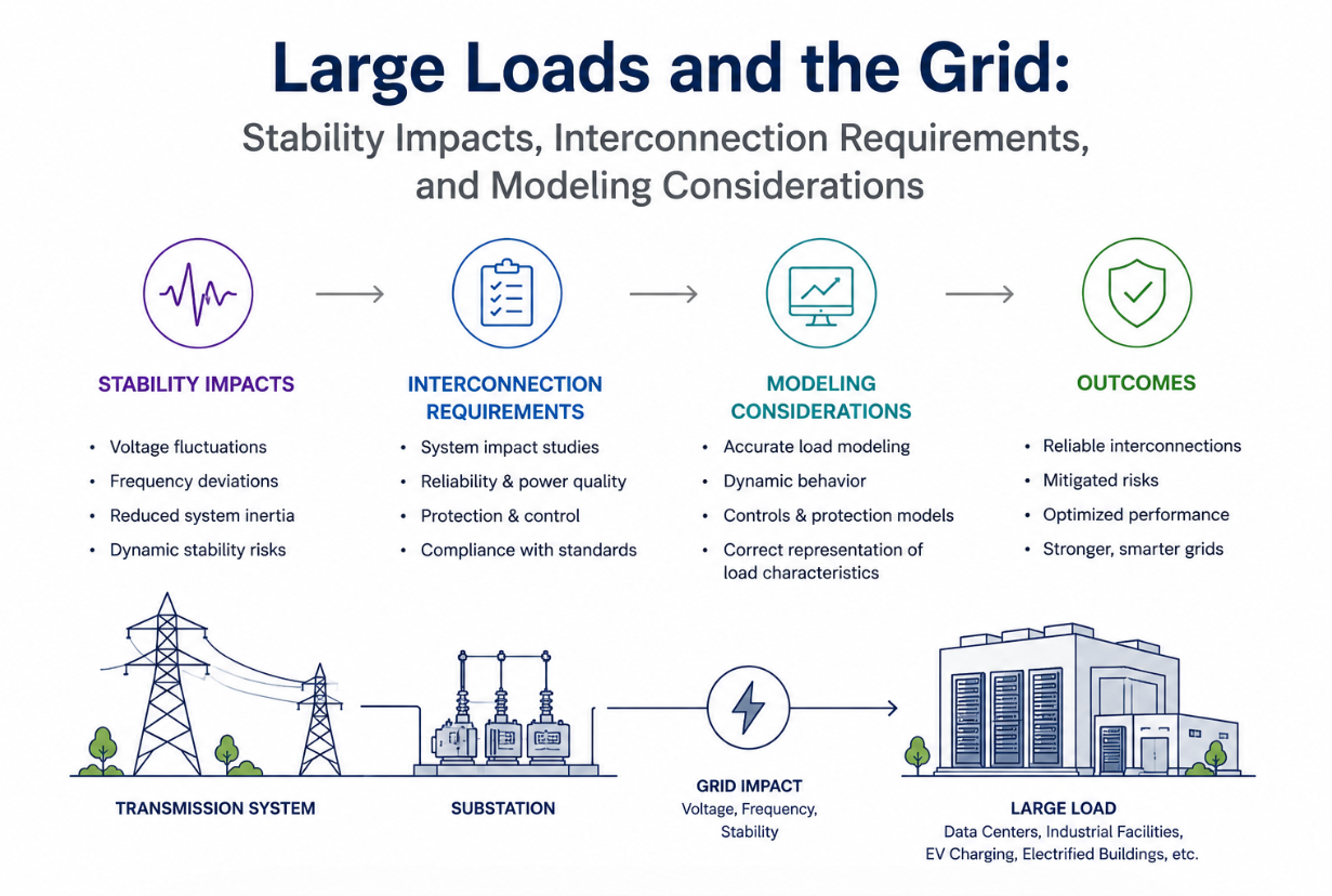
May 29, 2026 | Blog
Why Large Loads Suddenly Matter
For most of the last century, load was something the grid simply served. Forecasts were reasonably smooth, ramp rates were modest, and the dynamic behavior of demand rarely threatened system stability. That assumption is breaking down.
Modern data centers, particularly those built around AI training and inference, can reach hundreds of megawatts at a single site, with announced campuses approaching one to two gigawatts. At many utilities, the data center interconnection queue now exceeds the entire existing peak load of the system. A utility serving roughly 8.5 gigawatts at peak may find itself holding a few gigawatts of firm data center commitments and an interconnection queue larger than its whole footprint. This is not an incremental planning problem; it is a structural shift in what the demand side of the grid looks like.
The challenge is compounded by uncertainty. AI loads do not draw power smoothly. They cycle, ramp, and pulse in ways that depend on the workload, the orchestration software, and the physical architecture of the facility. When asked what their load will look like in the future, many operators honestly answer that they do not know. That single uncertainty cascades into nearly every downstream engineering decision.
How Large Loads Are Modeled
The three load categories inside a data center
A data center load is not monolithic. It is generally decomposed into three categories: electronic loads, cooling loads, and static loads. Electronic loads dominate, both because they represent the majority of the consumption and because they exhibit the unusual dynamic behaviors that create grid concerns. Cooling and static loads have their own characteristics, but the electronic load is where the stability story lives.
At the rack level, power supply units convert low-voltage AC (typically 400 to 480 volts) down to roughly 50 volts DC through a series of conversion stages: a front-end diode rectifier, a power-factor-correction stage, and a final chopper stage that steps the voltage down. Many facilities also include uninterruptible power supply (UPS) systems at the low-voltage side, in double-conversion, line-interactive, or rotary configurations, designed to bridge a grid outage for a few minutes. Battery backup units connect to the same DC bus through DC-DC converters and kick in when the grid is disturbed.
Constant power behavior and negative incremental impedance
A defining trait of these electronic loads is that they tend to behave as constant power loads: when voltage drops, current rises to keep power constant. From the grid's perspective, this presents a negative incremental impedance — a behavior engineers do not like but must capture accurately in their models, because ignoring it produces optimistic and misleading results. Importantly, these loads do not behave as constant power across the entire voltage range. In certain regions they switch to constant current behavior, which becomes critical when studying ride-through events and control interactions.
Choosing the right model fidelity
There is no single correct model for a data center load.
The right choice depends on the study. Three broad levels of electromagnetic transient (EMT) modeling fidelity are commonly used:
The **average model** represents the load with an adjustable RLC and appropriate current-limit controls. It reproduces constant power behavior over a range, captures oscillations the load forces onto the system, and scales well to very large systems.
It is well suited to subsynchronous oscillation and load-smoothing studies and gives conservative ride-through results. Its weakness is that it carries no switching detail, no harmonics, and no control interaction, and it can be unreliable during transitions.
The **average switching model** includes the control interactions but stops short of modeling the pulse-width-modulation (PWM) signals at the final stage, using a dependent voltage or current source instead.
It retains control dynamics well enough for many control interaction studies and preserves the interaction between battery backup units and power supply units.
The **detailed
switching model** includes the full switching and PWM detail. These models are typically built when a facility wants to specify and validate power supply unit performance against requirements.
They carry the full harmonic spectrum and are the right tool for high-frequency power quality and harmonic studies — but they are computationally expensive and do not add much value for the majority of grid-side studies.
A practical rule emerges: match fidelity to purpose. Grid-side studies often tolerate substantial simplification on the DC side, while device-level and power quality studies demand the detailed switching model. Scalability and simulation runtime differ dramatically across the three, and choosing more detail than the study requires wastes time without improving the answer.
The validation gap
A persistent problem is that vendor-specific models are often unavailable, and the information manufacturers do provide may be limited to specifications and occasional reference models of uncertain accuracy.
To close this gap, engineers have turned to hardware-in-the-loop lab testing. A representative setup uses two grid simulators — one emulating the AC side at 480 volts and one emulating the DC side — with the actual power supply unit in between.
This allows the team to subject the unit to severe and unusual disturbances and tune models until they reproduce the observed behavior.
One illuminating finding from this validation work concerns the handoff between the power supply unit and the battery backup unit during a voltage drop.
In a deep three-phase voltage sag (for example, an 80 percent drop), the power supply unit initially tries to hold constant power, so its current rises. As its hold-up energy depletes — reaching roughly half within tens of milliseconds — the DC bus voltage sags slightly, and the battery backup unit begins to share the load.
The two then share power for a period that can extend well over a hundred milliseconds for a severe sag, until the hold-up energy is exhausted and the battery carries the load.
Capturing this transition correctly matters for ride-through and control interaction studies, and it is precisely the kind of behavior that simplified models miss.
The Stability Problem: When Loads Make Generators Dance
Communication delay and the 20-millisecond trap
When
large loads are paired with on-site generation, batteries, and islanding capability — increasingly common in gigawatt-scale campuses targeting "five nines" (99.99 percent) uptime — the modeling problem becomes a system-of-systems problem, and small errors compound. An engineer might accept three percent error in an inverter model, three percent in the data center model, three percent in the generator model, and a larger margin in the poorly understood AI load itself.
Stacked together, these errors translate into very real money on a facility where an hour of lost output can represent tens of millions of dollars in revenue, plus reputational damage and litigation exposure.
One of the most under-appreciated sources of error is communication and measurement delay. A battery deployed to damp AI-load-induced oscillations must measure the load and counteract it, but the measurement signal arrives with delay from the communication bus.
In real-time studies using physical controllers, even a half-millisecond delay introduces visible oscillation.
At five milliseconds, a large fraction of the battery's damping capability is lost. At twenty milliseconds — a duration that sounds trivial — the battery's mitigating effect can essentially vanish, and the system can violate oscillation-based interconnection requirements that it appeared to satisfy in an idealized offline simulation.
The lesson is blunt: if the simulation does not model communication and measurement delay, the field results will not match, and by the time the equipment is installed, there may be nothing the engineer can do to fix it.
Torsional resonance and the synchronous machine shaft
The deepest stability concern involves synchronous generators near large variable loads. A generator's turbine-and-shaft system is a chain of masses connected by springs, and like any mechanical system it has torsional resonant modes at specific frequencies, each with different masses participating.
If a varying load excites the generator at one of these torsional frequencies and keeps doing so, the masses begin to move together at the resonant frequency, and the resonance grows.
Left unchecked, this mechanical resonance fatigues or breaks the shaft. This is the physical mechanism behind the "load makes the generator dance" metaphor, and it is one of the primary drivers behind the variability limits now appearing in interconnection requirements.
Studies on simple test systems — a load in parallel with an infinite grid and a synchronous machine with a torsional model — show that the load shape determines how active power variation propagates and amplifies at the machine shaft.
Certain continuously varying load shapes produce extreme amplification, on the order of several per unit of torque. A perfectly continuous, constant-phase forcing function exactly on a torsional frequency produces continuously growing torque; in an islanded condition this will, with certainty, eventually break the shaft. Even very small requirements — a few megawatts at a specific frequency — are not safe if the excitation lands precisely on a torsional mode under island conditions.
The mitigating reality is that real loads are unlikely to behave like the worst-case continuous forcing function.
Real load profiles show phase shifting, periods without torsional content, and discontinuity. When the phase shifts, damping is added for a while before the resonance can rebuild, producing growing and shrinking torques rather than unbounded growth.
The engineering question becomes probabilistic: how likely is a sustained, in-phase, constant-frequency excitation on a torsional mode? If the honest answer is "it could be anything," then requirements must be extremely tight or the load cannot connect. If the community can collectively quantify the risk as low, requirements can be relaxed.
The full stability umbrella
Torsional shaft damage is the most constraining concern, but it is not the only one.
The full list of stability and performance issues associated with large loads includes degradation of system damping, power quality and harmonics, ride-through failure impact, interactions with inverter-based resources, machine-mode and inter-area oscillations, subsynchronous oscillations, forced oscillations from nearby load processes, periodic transients, rotor angle and transient instability, frequency stability, resonance, converter-driven instability, resource adequacy, and steady-state thermal and voltage constraints.
Large loads exacerbate rotor angle instability in particular, which is not a risk the industry takes lightly.
Building Interconnection Requirements
Why existing frameworks fall short
Utilities generally have well-developed facility connection requirements for inverter-based resources, built up over a decade of integrating solar, storage, and grid-forming inverters.
There is meaningful overlap between that journey and the data center challenge, but it is not a one-to-one mapping, and existing documents written for generation cannot simply be pointed at a large load.
Many utilities are therefore drafting dedicated large-load interconnection requirements from a base of load study agreements, design-construction-and-operations agreements, and service agreements that historically offered little dynamic-performance specificity beyond references to harmonic, flicker, and electromagnetic-field standards, plus a general right to curtail.
The dimensions of a modern requirement
A comprehensive large-load interconnection requirement addresses several dimensions:
**Load variability (ramp) limits.** Utilities are converging on ramp-rate requirements expressed in megawatts per minute — figures such as 10, 20, or 30 MW/min appear across the industry.
Setting the number involves examining the utility's own generation ramp capability, historical variable-resource losses (such as several hundred megawatts of solar lost over a few minutes), and the behavior of other variable loads like arc furnaces.
One utility, after this analysis, landed on roughly 10 MW/min as a starting point — explicitly acknowledging it is not perfect and will be refined over time.
The terminology matters too; some prefer "load variability" over "ramp limit," which carries narrower connotations.
**Ride-through.** With no established industry standard for ride-through settings, this is widely viewed as low-hanging but urgent fruit. Real events have already occurred in which a fault caused a data center to drop a large fraction of its load and return online seconds later — exactly the abrupt load swing the system must be coordinated to handle. Strong coordination between utility and facility on UPS behavior and internal protection settings is essential.
**Power factor.** Though not strictly a reliability issue, power factor is a live topic.
Utilities generally want to move toward unity, since a low power factor creates cost consequences for the customer and reinforces a shared interest in correction.
**Harmonics, voltage distortion, and flicker.** Established standards such as IEEE 519 have existed for a long time, but real installations can exceed current or voltage harmonic limits, and requirements need to become more specific over time.
Connecting large loads at high transmission voltages (230 or 500 kV) helps, but more analysis with trusted experts is needed, particularly on flicker.
**Monitoring.** Requirements increasingly specify monitoring equipment — power quality monitors, phasor measurement units, and digital fault recorders — and the metering granularity needed to observe intra-second behavior and feed it into control-room standards.
**System stability and load modeling.** Requirements must ultimately address the full stability umbrella and specify the load models the customer must provide for interconnection studies.
**Forecasting, outage coordination, and recovery.** Gigawatt-scale loads take outages, which raises a question the industry has not fully addressed: what happens when a massive load suddenly drops or returns? Existing outage coordination protocols were built for generation and transmission, not for loads of this scale.
And observing major system events abroad has prompted a further question: ride-through requirements focus on behavior during and shortly after a disturbance, but should they also address the recovery phase? Some electronics might survive the disturbance itself yet fail during restoration — and rapid restoration is exactly what limits the damage of a major blackout.
Two philosophies for variability limits
Two broad frameworks exist for limiting active power variation. A **surgical** approach uses frequency-domain analysis to target specific frequencies — for instance, a very small limit (a few megawatts) at a particular frequency known to be problematic.
A **blunt** approach simply caps active power variation more broadly.
Both appear in current requirements. Because they are being written conservatively on the basis of limited real-world data and incomplete confirmation from equipment manufacturers, these limits will need continuous tuning as better data arrives.
A Programmatic Approach: Operational Readiness
Rather than treating data center integration as a series of isolated engineering fixes, some utilities are adopting a programmatic approach modeled on their inverter-based-resource integration journey.
One such "operational readiness" model organizes the work into a handful of themes — covering reliability and cost roughly equally — and a portfolio of supporting projects, with the explicit goal of preparing for the future grid safely, reliably, and cost-effectively.
A distinguishing feature of this approach is broad stakeholder involvement.
Rather than letting transmission planning or the transmission operator lead in isolation, the model gives economic development, system planning, power delivery engineering, project management, account management, energy management, operations, and operational technology all a seat at the table.
This breadth tends to surface creative solutions that a narrower, single-department effort would miss.
Applied to
data centers
the approach typically proceeds through level-setting and gap analysis — summarizing industry efforts, soliciting internal concerns, and cataloging gaps — before defining a strategy and a set of projects covering ride-through, power quality monitoring, bulk-system balancing under AI variability, and interconnection studies and modeling.
A small cross-functional team is often tasked with refining scope and, most importantly, drafting the interconnection requirements themselves.
The Road Ahead
Several threads point toward where this field is heading.
Industry bodies have begun publishing technical conference papers and white papers on large loads, with a prominent recommendation to seek a formal reliability functional designation for large loads and to develop standards on an aggressive timeline. The regulatory arc that brought inverter-based resources from voluntary guidance to mandatory reliability standards offers a template, and utilities are choosing not to wait for that process to complete before acting.
Equipment manufacturers are also rising to the challenge. There are demonstrations of electronics engineered to meet — and reportedly exceed — even the most stringent ride-through requirements published to date. Solutions are emerging from multiple directions at once: from the large-load sector, from utilities, from grid-forming inverter and battery groups, and from specialized consultants.
Techniques such as back-to-back battery conversion — placing two inverters back-to-back so that AI-load oscillations are absorbed on the DC side rather than passed through to the system — offer a path to compliance with strict oscillation limits, albeit at higher capital cost that can nonetheless be justified against the enormous value at stake.
The honest summary is that this is an evolving continuum.
The requirements being written today are first drafts, conservative by necessity and built on thin data.
They will be tuned and re-tuned as measurements accumulate, as manufacturers confirm what their equipment can and cannot do, and as the community collectively decides how much reliability risk it is willing to accept.
If risk is framed in operational terms — the imperative to keep the lights on — the solutions are within reach.
The work now is to integrate those solutions rather than simply accumulate the risks.
Case Studies
The following three case studies are anonymized and composited to illustrate common situations.
Identifying details have been omitted intentionally.
Case Study 1: The Commissioning Delay That Modeling Could Have Prevented
A developer building a large facility with on-site generation, battery storage, and islanding capability completed extensive offline studies in both phasor-domain and EMT software.
Every model behaved acceptably in simulation, and the project moved to field commissioning with confidence.
In the field, the picture changed. Field tests revealed mismatches above the acceptable threshold between measured behavior and the models.
The original equipment manufacturer maintained that its models were correct; the study team maintained that the models contained errors.
The dispute stalled commissioning. What had been a confident schedule slipped into weeks, and the cumulative delay ultimately proved fatal to the project's economics.
The root cause traced back to unmodeled dynamics — most notably communication and measurement delays in the control loop responsible for damping load-induced oscillations. In the idealized offline studies, the damping appeared fully effective. In reality, even a few milliseconds of delay sharply reduced the battery's ability to counteract oscillation, and the field behavior diverged from the model.
The lesson the team carried forward was unambiguous: communication and measurement delays must be represented in the study phase, because once equipment is installed, cable lengths and hardware cannot be retrofitted to recover lost margin.
**Takeaway:** Validate models against realistic, delay-inclusive conditions before procurement.
A modeling assumption that looks negligible — a handful of milliseconds — can determine whether a project commissions on time or not at all.
Case Study 2: Drafting Interconnection Requirements From a Blank Page
A vertically integrated utility serving several gigawatts at peak found its data center interconnection queue had grown larger than its entire existing peak load, with a few gigawatts of firm commitments already on the books.
Its existing agreements — load study, design-construction-and-operations, and electric service — referenced harmonic, flicker, and electromagnetic-field standards and preserved a right to curtail, but offered little dynamic-performance specificity.
Its dedicated facility connection requirements had been written for inverter-based generation and could not legitimately be pointed at a large load.
Rather than retrofitting old documents, the utility stood up a cross-functional team and tasked it specifically with drafting new large-load interconnection requirements.
The team began by summarizing the existing interconnection process and surveying industry efforts, then worked through each requirement dimension in turn.
For load variability it examined its own generator-by-generator ramp capability, historical events in which several hundred megawatts of variable generation were lost over a few minutes, and the behavior of other variable loads, ultimately adopting a ramp-rate figure as a deliberately imperfect starting point to be refined.
It addressed ride-through coordination after a real event in which a facility dropped a large fraction of its load following a fault and returned seconds later.
It moved power factor toward unity, tightened its approach to harmonics and flicker, specified monitoring equipment, and connected new large loads at high transmission voltages.
**Takeaway:** Existing generation-oriented frameworks are a poor fit for large loads. A structured, cross-functional effort that catalogs gaps and addresses each requirement dimension explicitly — while accepting that first-draft numbers will need tuning — is a more durable path than stretching legacy documents to cover a problem they were never designed for.
Case Study 3: Quantifying Torsional Risk to Avoid Over-Conservative Limits
A studies-and-simulation team spent considerable effort on a single, deceptively small technical problem with outsized consequences: how to set active power variation limits that protect synchronous generator shafts from torsional resonance without being so conservative that large loads simply cannot connect.
Using a simple test system — a load in parallel with an infinite grid and a synchronous machine with a torsional model — the team showed that the shape of the load's power variation determines how strongly it amplifies at the machine shaft.
Some continuous, constant-phase load shapes on a torsional frequency produced amplification of several per unit of torque and, in islanded conditions, unbounded growth that would certainly damage a shaft.
When the team asked equipment vendors whether their loads could ever take such a worst-case shape, the honest answer was that they could not rule it out.
That uncertainty created a dilemma.
If the load could behave like the worst case, limits would have to be extremely small or zero, effectively barring connection.
But measured real-world profiles looked far more benign — showing phase shifting, periods without torsional content, and discontinuity, all of which interrupt resonance growth. The team's conclusion was that the path forward is probabilistic: rather than designing for an unbounded worst case nobody can confirm, the community must collectively quantify how likely sustained in-phase torsional excitation actually is.
If that risk can be shown to be low, limits can be relaxed responsibly. In the interim, the team recommended protecting generators directly by monitoring the synchronous components of terminal currents and increasing inspection frequency.
**Takeaway:** Setting variability limits is as much a risk-acceptance question as a technical one. Without better data on real load behavior, requirements default to extreme conservatism.
Quantifying the probability of worst-case torsional excitation — and protecting machines directly in the meantime — is what allows requirements to be both safe and workable.
Frequently Asked Questions
Q1.What exactly makes AI data center loads different from traditional large loads?
Traditional large loads draw power relatively smoothly and predictably. AI computing loads cycle, ramp, and pulse based on workload and orchestration, producing variability with frequency content, ramp rates, and duty cycles that can interact adversely with the grid. Critically, their future behavior is uncertain even to their operators, which forces planners to design around a range of possibilities rather than a known profile.
Q2.Why is "constant power" behavior a concern?
Electronic data center loads tend to hold power constant as voltage changes, so when voltage drops, current rises. From the grid's perspective this creates a negative incremental impedance, which can degrade stability and damping. Models must capture this behavior — and the fact that the load may switch to constant current in some voltage ranges — or they will produce misleadingly optimistic results.
Q3.What is torsional resonance and why does it threaten generators?
A synchronous generator's shaft is a chain of masses and springs with natural torsional resonant frequencies. If a nearby load varies its power at one of those frequencies and sustains it, the shaft begins to oscillate at that frequency and the oscillation grows. Sustained growth fatigues or breaks the shaft. In an islanded system with a sustained in-phase excitation on a torsional mode, shaft damage is essentially certain over time.
Q4.Why does a 20-millisecond delay matter so much?
Batteries used to damp load-induced oscillations rely on measuring the load and reacting to it. Communication and measurement delays mean the battery acts on slightly stale information. Even a few milliseconds of delay erodes damping effectiveness substantially, and around twenty milliseconds the damping benefit can disappear entirely — turning a design that looked compliant in an idealized simulation into one that violates oscillation limits in the field. Because cable lengths and hardware cannot be changed after installation, the delay must be modeled up front.
Q5.Which load model should I use for my study?
Match fidelity to the study. Use an average model for subsynchronous oscillation and load-smoothing studies and for large, scalable system simulations where switching detail is unnecessary. Use an average switching model when control interactions matter but full harmonic detail does not. Use a detailed switching model for device-level, harmonic, and high-frequency power quality work. More detail than the study requires only costs runtime without improving the answer.
Q6. Why do utilities need new interconnection requirements instead of reusing existing ones?
Existing facility connection requirements were written for inverter-based generation, not for large loads, and cannot simply be repurposed. While the integration journeys overlap, large loads introduce distinct concerns — ramp variability, torsional interaction, ride-through of computing electronics, and outage behavior at gigawatt scale — that demand dedicated requirements.
Q7. What is a typical ramp-rate limit, and how is it set?
Limits are commonly expressed in megawatts per minute, with figures such as 10, 20, or 30 MW/min in use. Utilities set them by examining their own generation ramp capability, historical variable-resource loss events, and the behavior of comparable variable loads, then choosing a starting value they expect to refine as data improves.
Q8.Are the strictest requirements enough to guarantee safety?
Not necessarily. Even very small limits at specific frequencies can be unsafe if the excitation lands precisely on a torsional mode under island conditions. Safety depends not just on magnitude but on frequency, phase persistence, and system configuration — which is why quantifying the probability of worst-case excitation is so important.
Q9. What can be done to protect generators in the meantime?
Until the loads are better understood, monitor the synchronous components of generator terminal currents, watch for growth, and consider acting on that information. Increasing the depth and frequency of rotor and machine inspections is also prudent, though it carries cost.
Q10.Is there a hardware solution for oscillation compliance?
Yes. Back-to-back battery conversion — placing two inverters back-to-back so AI-load oscillations are absorbed on the DC side and not passed to the system — is one emerging technique. It costs more than a simple parallel battery but can be justified by the very large financial and reliability stakes involved.

About the Author:
Sandip "Sonny" R. Patel, P.E.
IEEE Senior Member · Founder & CEO, Keentel Engineering
In 1995, Sonny Patel earned his Electrical Engineering degree from the University of Illinois. But degrees don't build legacies — action does.
For three decades, he has worked the power industry from every side of the table: 16 years as a utility engineer at Exelon/Commonwealth Edison; generation leadership across hydroelectric, industrial steam turbine, and a 9 GW renewable fleet; NERC Regional Entity Senior Compliance Engineer and Audit Team Lead, auditing some of the nation's largest utilities; and testing and commissioning lead on equipment up to 765 kV — the very top of the North American grid.Utility. Generator. Regulator. Consultant. Few engineers have seen all four seats. Fewer still have sat in them.
His experience spans nuclear, hydro, conventional generation, renewables, oil and gas, mining — and today's data centers, where he is authoring a three-book series on data center design. He is a Licensed Professional Engineer in six states and a Licensed Electrical Contractor in Florida (Unlimited EC) — he doesn't just design the work; he's qualified to stand behind its execution.Today, as Founder and CEO of Keentel Engineering, Sonny leads a nationwide team of engineers delivering substation design, power system studies, NERC compliance, and commissioning — done right, coast to coast.Three decades. Every side of the table. One standard: accountable engineering.
Services

Let's Discuss Your Project
Let's book a call to discuss your electrical engineering project that we can help you with.
About the Author:
Sandip "Sonny" R. Patel, P.E.
IEEE Senior Member · Founder & CEO, Keentel Engineering
In 1995, Sonny Patel earned his Electrical Engineering degree from the University of Illinois. But degrees don't build legacies — action does.
For three decades, he has worked the power industry from every side of the table: 16 years as a utility engineer at Exelon/Commonwealth Edison; generation leadership across hydroelectric, industrial steam turbine, and a 9 GW renewable fleet; NERC Regional Entity Senior Compliance Engineer and Audit Team Lead, auditing some of the nation's largest utilities; and testing and commissioning lead on equipment up to 765 kV — the very top of the North American grid.
Utility. Generator. Regulator. Consultant. Few engineers have seen all four seats. Fewer still have sat in them.
His experience spans nuclear, hydro, conventional generation, renewables, oil and gas, mining — and today's data centers, where he is authoring a three-book series on data center design. He is a Licensed Professional Engineer in six states and a Licensed Electrical Contractor in Florida (Unlimited EC) — he doesn't just design the work; he's qualified to stand behind its execution.
Today, as Founder and CEO of Keentel Engineering, Sonny leads a nationwide team of engineers delivering substation design, power system studies, NERC compliance, and commissioning — done right, coast to coast.Three decades. Every side of the table. One standard: accountable engineering.
Leave a Comment
Thank you for contacting us.
We will get back to you as soon as possible.
We will get back to you as soon as possible.
Oops, there was an error sending your message.
Please try again later.
Please try again later.
Related Posts

By SANDIP R PATEL
•
October 3, 2026
Engineering guide to PRC-028 disturbance recording, PRC-029 ride-through and PRC-030 event detection for inverter-based resources.

By SANDIP R PATEL
•
October 3, 2026
A practical guide to SSO classification, SSR, PEDI, Wind-SSCI, EMT analysis, mitigation and protection based on CIGRE TB 909.

By SANDIP R PATEL
•
October 3, 2026
Learn ERCOT generator testing for PFR, MOD-025 and MOD-026/027, including staged tests, capability verification, dynamic models and field testing.

By SANDIP R PATEL
•
October 3, 2026
Learn how PV string I-V curve testing identifies hidden solar performance losses, including soiling, shading, mismatch, degradation, and wiring faults.

By SANDIP R PATEL
•
October 3, 2026
Learn how active harmonic filters work, how to size AHF systems, reduce VFD harmonics, calculate losses, and meet IEEE 519 TDD limits at the PCC.
By SANDIP R PATEL
•
October 3, 2026
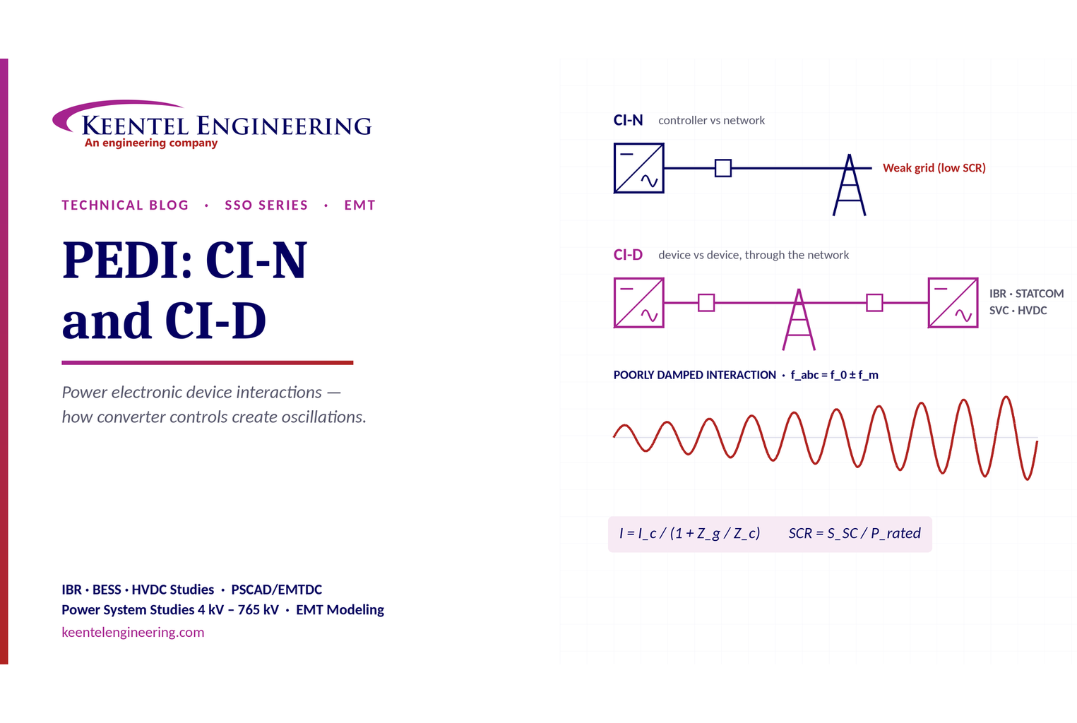
Learn power electronic device interactions (PEDI), including CI-N and CI-D, weak-grid stability, SCR, EMT studies, impedance analysis and mitigation for IBRs.
By SANDIP R PATEL
•
October 3, 2026
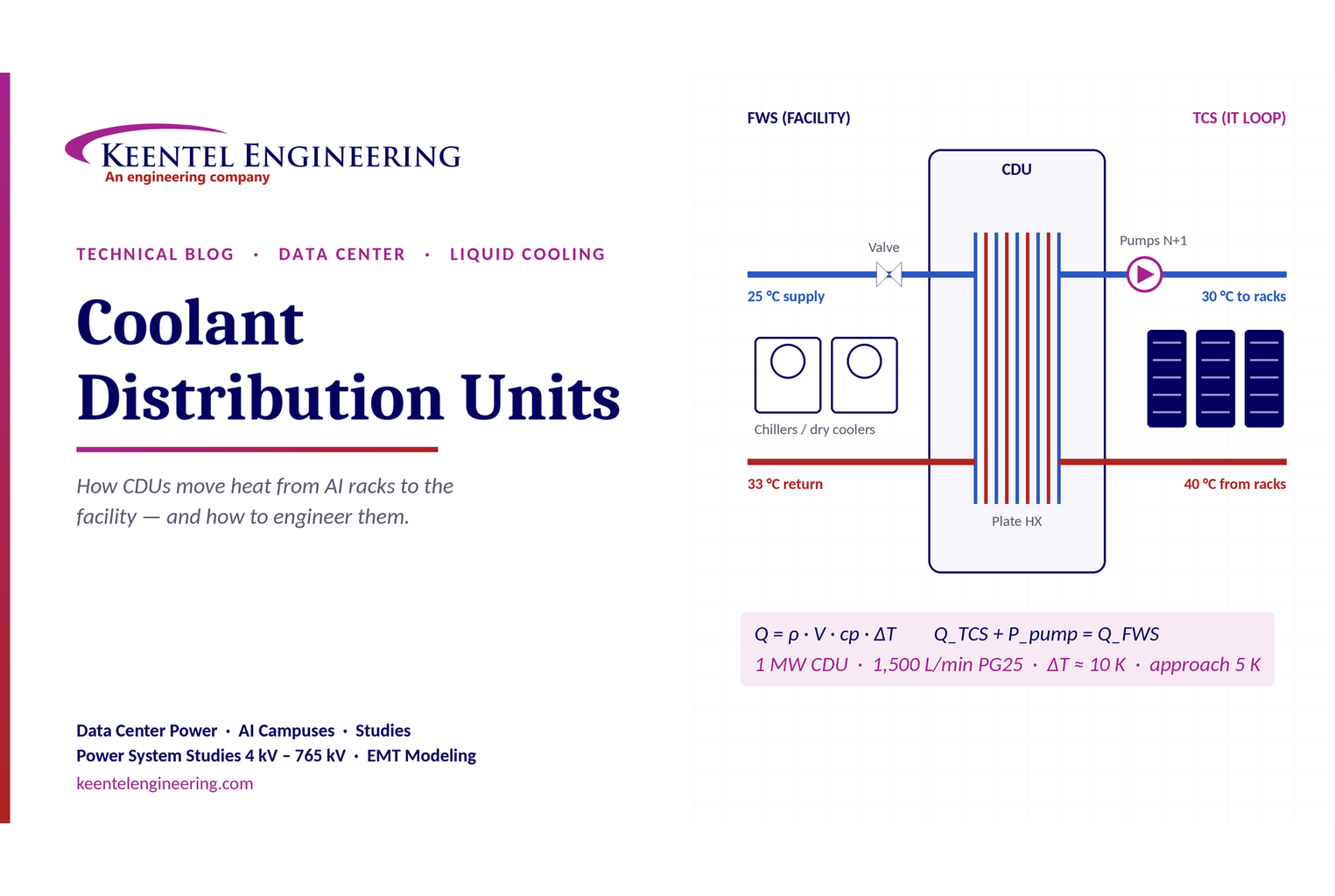
Learn how data center coolant distribution units (CDUs) work, including FWS and TCS loops, heat transfer, sizing, redundancy and liquid cooling for AI data centers.
By SANDIP R PATEL
•
October 3, 2026
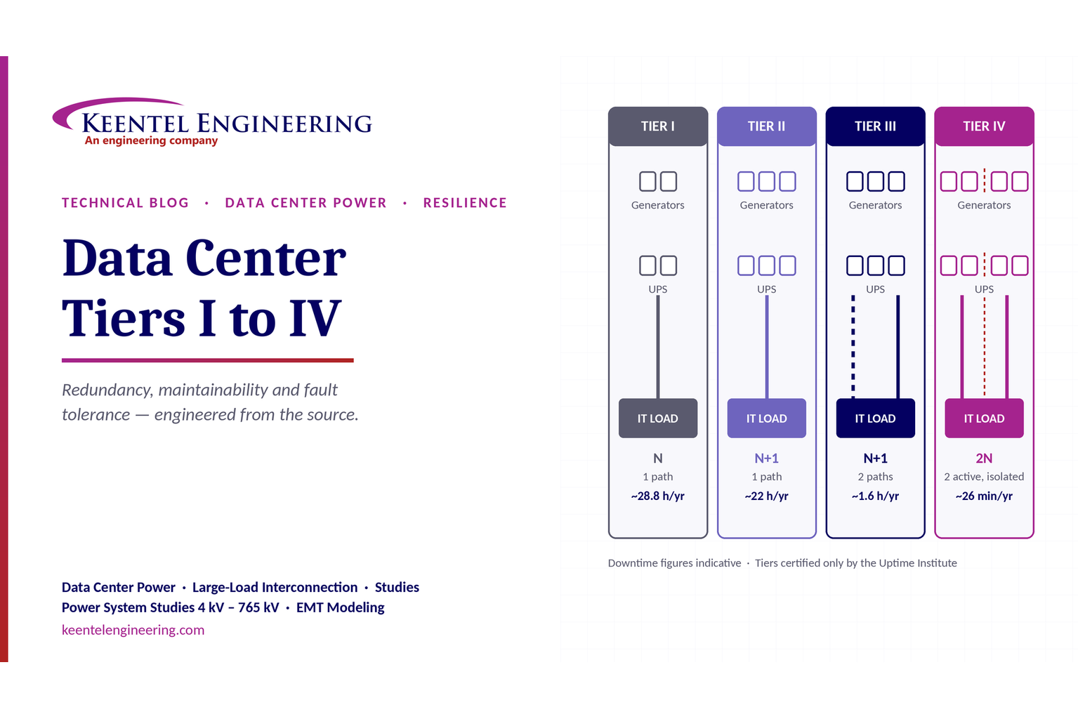
Compare Data Center Tiers I–IV, including redundancy, uptime, Tier III concurrent maintainability, Tier IV fault tolerance, UPS, generators and power design.

By SANDIP R PATEL
•
October 3, 2026
Learn how BESS supports grid stability through fast frequency response, voltage support, oscillation damping, black start, grid-forming controls and EMT studies.





