
A Coordinated Electric System Interconnection Review—the utility’s deep-dive on technical and cost impacts of your project.
Challenge: Frequent false tripping using conventional electromechanical relays
Solution: SEL-487E integration with multi-terminal differential protection and dynamic inrush restraint
Result: 90% reduction in false trips, saving over $250,000 in downtime
Power Transformer Testing &Commissioning
Jul 02, 2026 | Blog
How disciplined pre-energization testing protects the most expensive asset in your substation from nameplate verification and TTR to winding resistance, insulation evaluation, and final trip checks.
1. Why Transformer Commissioning Testing Matters
High-voltage power transformers are among the most important — and most expensive — pieces of equipment in any substation. Whether a unit arrives new from the factory or is relocated from another site, it cannot simply be bolted down, filled with oil, and energized. Before the first energization, the commissioning team must verify that the transformer is dry, that no damage occurred during shipping, that internal connections have not loosened in transit, that the measured ratio, polarity, and impedance agree with the nameplate, that the major insulation structure is intact, and that no wiring insulation has been bridged or scraped.
The scope of that verification scales with the machine. Physical size, voltage class, and kVA rating dictate how much preparation, how many auxiliary devices, and how much testing is required before a transformer can be certified ready for energization. A distribution-class unit may need only a handful of checks; a large EHV autotransformer bank demands a coordinated campaign of insulation, ratio, impedance, winding-resistance, CT, cooling-system, and protection testing — and a single responsible test engineer who confirms every item is satisfactorily complete before the final go/no-go decision.
The Keentel Perspective
Commissioning test data is not just a gate to energization — it is the fingerprint of the transformer in its healthy, as-installed condition. Every ratio, impedance, winding-resistance, and insulation reading taken on day one becomes the diagnostic baseline against which every future maintenance test, post-fault assessment, and end-of-life decision will be compared. Sloppy baseline data devalues the asset for its entire service life.
2. The Recommended Test Sequence
Transformer testing is most efficient and safest when it follows a deliberate sequence. A proven field sequence looks like this:
- Inspect the transformer and all shipped components for shipping damage and moisture ingress.
- Verify nameplate data and drawings for correct voltages and the external phasing connection to the line or bus.
- Check calibration of all thermal gauges, the hot-spot heater circuit, and RTDs, and verify alarm contact settings (typical staging: one cooling stage running continuously, second stage near 80 °C, third stage near 90 °C, hot-spot alarm near 100 °C with trip near 110 °C where applicable).
- Point-to-point wire check and megger all transformer wiring: fans, pumps, alarms, heaters, tap changers, and interconnecting cables.
- Vacuum-dry large banks (a common threshold is units above roughly 150 MVA). Never apply test voltage to windings during vacuum drying, and keep terminals shorted and grounded during oil circulation because of static charge buildup on the winding.
- After oil filling, confirm an oil sample has gone to the chemistry lab and record oil level and temperature at completion.
- Power-operate pumps and fans to verify rotation, and exercise the under-load (UL) tap changer, heaters, and alarms.
- Perform winding tests: ratio and polarity (TTR preferred for units above 1 MVA), impedance, DC winding resistance, and megger/power-factor of windings, bushings, and arresters waiting 24 hours after oil filling before power-factor testing.
- Load CT circuits overall and flash CTs for polarity.
- Trip-check all bank protection schemes and confirm the gas-collection relay is free of gas before energization.
- Energize while monitoring bank currents, voltages, and UL tap-changer operation; verify phasing to the system before picking up load. Where possible, let large units soak energized for eight hours before carrying load.
- Make in-service checks on meters and relays, release to operations, and turn in complete test reports including all test data, moisture and oil data, problems encountered, and in-service readings.
3. Nameplate Data and Terminal Markings
Recording nameplate data is not a test, but it is mandatory — and it forces the test crew to become intimately familiar with the unit. The main tank, the under-load tap changer, bushing CTs, bushings, fuses, fan and pump motors, surge arresters, and disconnect switches all carry individual nameplates, and every pertinent field on the test data sheet should be completed.
Terminal marking follows ANSI convention. Two-winding transformers use H for the higher-voltage winding and X for the lower-voltage winding; viewed from the high-voltage side, the H1 bushing is on the right. Transformers with three or more windings add Y and Z designations in order of decreasing voltage rating, with H assigned to the highest-voltage (or, for equal voltages, highest-kVA) winding.
4. Auxiliary Wiring Checks and Hand Meggering
Every wire on the transformer should be verified before energization control panels, terminal cabinets, cables routed to the unit, and every screw, nut, and bolt terminal torqued for tightness, including CT leads where they originate at the bushing connection boxes. A thorough wire check protects a unit that may be difficult, expensive, or impossible to replace; it also cross-checks the drawings against physical reality and familiarizes the crew with the equipment.
All low-voltage wiring should be meggered at 250 or 500 VDC. The emphasis is deliberate: large transformers carry numerous small terminal boxes interconnected by conduit that can accumulate moisture or leak, and wire pulled through metal conduit is occasionally scraped down to bare copper. Boxes mounted on vertical surfaces should have small drain holes; horizontal-surface boxes need sound weather seals, and any questionable gasket should be replaced. Completing wire checks and low-voltage meggering early allows control and alarm power to be applied safely which in turn makes tap-changer and cooling-system testing far faster than hand-cranking mechanisms.
5. Bushing CT Testing: Ratio, Polarity, and the Flash Test
5.1 Ratio Verification
Bushing CTs are best tested by the Current Ratio method — ideally before they are mounted, or with high-capacity current leads pulled through the CT windows before bushings are inserted. Where primary current injection is impossible, a Tap Voltage Ratio test (energizing the full winding and measuring the drop across each tap) can verify tap ratios, since voltage ratios are directly proportional to turns ratios. But the voltage method is a last resort: it cannot establish the true installed polarity or verify the primary-to-secondary ratio, and testing at rated current always provides more assurance that the CT will perform in service.
5.2 Flashing CTs for Polarity
CT polarity is commonly verified by “flashing” — applying 6–12 VDC to the transformer bushings and making/breaking the circuit with a hot stick. Battery positive connects to the polarity (high-voltage) terminal; battery negative is touched to the non-polarity end or station ground through the hot-stick lead. An analog voltmeter across the CT secondary (polarity side to X1) should deflect upscale on make and downscale on break if polarity is correct. Series current-limiting resistance is advisable with automotive batteries, and shorting the windings on the side opposite the flash limits arc energy.
Safety Warnings — DC Flash Testing
A winding carrying DC current generates a large voltage kick when the circuit is opened. Always make and break the connection with an insulated hot stick never by hand.
Never make or break connections directly on a lead-acid battery terminal; charging batteries evolve hydrogen and have exploded from connection sparks.
Never place your body in series with the test circuit by holding a battery clip in one hand while touching the terminal with the other.
Flashing does leave residual magnetism in the CT core which, in theory, could contribute to CT saturation and improper relay operation on initial energization. After a high-current DC flash, demagnetize the core: apply AC excitation gradually, drive the CT just into saturation with the secondary open, then slowly reduce the AC quantity to zero.
6. Insulation Power Factor Testing
Bushings first
Every bushing should be power-factored before insertion into the transformer. If no power-factor set is available during assembly, at minimum measure C1 and C2 capacitance with a bridge — a capacitance shift can flag a serious internal bushing problem before it is buried in the tank — and megger the bushing and its tap at 2,500 V (checking first that small bushing taps may be limited to 500–1,000 V).
Then the transformer
Power-factor the complete transformer soon after drying and oil filling, and re-test all bushings, since readings shift slightly after assembly. A complete data set includes winding-to-winding, winding-to-ground, and bushing tests, plus a winding excitation test where the test set has sufficient capacity. Critically, wait 24 hours after completion of oil filling before power-factor testing — oil and insulation need time to reach equilibrium for meaningful readings.
7. Ratio and Polarity Testing
7.1 Subtractive vs. Additive Polarity
Winding polarity describes the relative direction of instantaneous voltage at the terminals, determined by winding direction and lead routing. If adjacent HV/LV terminals share the same instantaneous polarity, the transformer is subtractive; if diagonally opposite terminals match, it is additive. Polarity matters whenever windings or transformers are paralleled, and when establishing three-phase connections. As a rule, transformers above 500 kVA are built subtractive.
7.2 DC Flashing Method
With a small dry-cell battery intermittently connected to the HV winding and a DC voltmeter on the LV terminals, an upscale kick on make and downscale kick on break indicates subtractive polarity; the reverse indicates additive. The inductive kick on break is much larger than on make. Crisp “make/break” call-outs between the battery operator and meter observer, a healthy battery, and low-resistance bushing connections make deflections easy to read.
7.3 AC Method
Energize the HV winding, jumper the two adjacent HV/LV bushings together, and read a polarity voltmeter across the open pair: VPOL = VH − VX indicates subtractive polarity; VPOL = VH + VX indicates additive. The AC polarity check is conveniently performed during the voltage-ratio test.
7.4 Voltmeter Ratio Method
The voltmeter method uses a fused 115 VAC source, a variable autotransformer, an ammeter, and precision voltmeters (0.5%-class or 4½-digit DVMs for 1% ratio accuracy). Test voltage is typically 1/1000 of winding rating or less, which makes evaluation intuitive: if the nameplate tap says 112,750 V : 13,800 V, energize the HV winding at 112.75 V and expect 13.80 V on the low side. Read every tap-changer position, pre-calculate expected values on the data sheet, connect voltmeter leads directly to bushing terminals (never through the source leads), and monitor input current to catch shorted turns or connection problems immediately.
7.5 TTR — The Preferred Method
The Transformer Turns Ratio test set compares the unit under test against an adjustable-ratio reference transformer using a null detector, determining polarity by comparison in the same operation. TTR is the preferred ratio method, with accuracy on the order of 0.1%, and should be performed on every new high-voltage power transformer at installation and on any unit that has been overhauled or relocated. Its repeatability makes it the diagnostic base for future maintenance comparisons — and the single most useful data set when a shorted turn is suspected. The voltmeter method still earns its place: it verifies proper tap-changer make/break behavior and converts easily into the impedance test setup.
High-Ratio Hazard
Extreme caution is required when test-energizing high-ratio transformers. Even low test voltages applied to a low-voltage winding are stepped up at the HV terminals — for example, 120 V applied to the wye side of a 230 kV delta / 13.8 kV wye bank can generate roughly 3.5 kV between H-side bushings. Apply test voltage to the highest-voltage winding whenever the hands-on nature of the test allows, fence off exposed areas, and warn all personnel.
8. Short-Circuit Impedance Testing
Impedance measurements — compared against nameplate and retained for future diagnostics — detect shipping damage, loose or high-resistance connections, and in some cases shifting of the core and coils from mechanical or electrical damage. A short-circuit impedance test should be performed on:
- Installation as a new unit
- Any overhaul
- Any internal connection change (other than tap-changer operation)
- Reinstallation at another location
- Any unit subjected to a severe fault where winding or tap-changer damage is possible
Because power transformers are highly linear, impedance can be measured at rated frequency using currents and voltages that are a small fraction of rating. Practical rules: use a sinusoidal (preferably regulated) source above 7 V, RMS meters of 0.5% class or 4½ digits, measure voltage directly at the transformer terminals, and record ratio and impedance for every tap position. Short-circuit jumpers must be heavy (2/0 or 4/0), short, and clamped tight — a high-resistance short reads as high impedance. In practice the resistance of heavy shorting leads introduces well under 0.5% error even on high-ratio windings; contact resistance is the more likely culprit.
Acceptance guidance:
measured impedance should compare with nameplate within about 5% (nameplate comparison is only valid on the nominal tap); if it deviates more, re-measure from the alternate direction or use phase-to-phase methods. Comparisons between phases of the same unit should agree within about 2%. On a 9.0% impedance transformer, expect field values between roughly 8.8% and 9.2%.
8.1 Connection-Specific Nuances
Percent-impedance formulas depend on winding connection, and this is where mistakes happen. A few field-critical points:
- Delta-delta units read double. A single-phase impedance measurement on a delta-delta transformer yields roughly twice the nameplate %Z, because the nameplate lists a three-phase wye-equivalent through-impedance. Matching nameplate requires a three-phase short on the opposite winding, phase-to-phase test quantities, and averaging the three measurements.
- You cannot short one winding of a delta. Any short applied to one delta winding also short-circuits the other two; test current flows in all windings. The same limitation applies to wye windings without an accessible neutral.
- Zero-sequence impedance. For grounded-wye windings, short all three phase bushings together, apply single-phase voltage from the shorted bushings to neutral, and compute %Z0 with the appropriate 3× KVA factor. Zero-sequence quantities matter because delta-wye grounded banks are the principal sources of zero-sequence current during ground faults, and correct ground-relay operation depends on them. Zero-sequence impedance is infinite looking into an ungrounded wye or a delta winding.
- Verify before tear-down. Always calculate %Z from measured quantities and confirm agreement with the nameplate before dismantling the test setup, so anomalies can be re-checked on the spot.
9. DC Winding Resistance Measurement
Winding resistance verifies that no loose connections, discontinuities, or internal lead problems exist and that shipping has not loosened connections inside the tank. Field data is compared with factory values to validate the as-received condition, used to determine average winding temperature, and retained as a diagnostic benchmark for the transformer's later life.
9.1 Method Selection and Technique
Two families of methods are used: bridge measurement and the volt-amp (V/I) method. The Wheatstone bridge suits windings above 1 Ω (accuracy around 0.05%, but test-lead resistance must be measured immediately after the test and subtracted). The Kelvin bridge and four-terminal volt-amp methods suit low-resistance windings below 1 Ω, because four-terminal measurement excludes lead resistance — connect current leads outside the potential leads, closest to the unknown resistance. Universal rules: connect directly to winding/bushing terminals (never through bus), keep test current below 15% of winding rating to avoid heating, allow 30 seconds to several minutes for current to stabilize before reading, measure winding temperature before and after, bridge every tap position where time allows (at minimum the maximum-winding tap and nominal tap), and operate tap changers several times beforehand so contact wiping establishes low resistance.
9.2 Temperature Correction
Resistance readings are only comparable when normalized. For copper windings, RB = RX × (234.5 + TB) / (234.5 + TX), with standard base temperatures of 20 °C, 75 °C, or 85 °C. For aluminum windings the constant becomes 228.1, and for 97% hard-drawn copper, 241.5. The same relationship, inverted, converts a measured resistance into average winding temperature — the basis of heat-run temperature determination.
The Stored-Energy Hazard
A transformer winding is a very large inductor. Unlike a capacitor, which discharges through a short circuit, an inductor releases its stored energy when the current path is opened — and the voltage generated by a collapsing field can reach kilovolts, arc through open switches, destroy test instruments, and deliver a potentially fatal shock.
Always provide a discharge path (short circuit, discharge resistor, or a temporarily shorted second winding) before de-energizing the DC source. Do not open the short until a series ammeter reads zero — discharge can take 30 seconds to 2 minutes, and prudent practice is to wait at least five minutes before touching connections. Sizing the discharge resistor at R = 100/Ix limits peak discharge voltage to 100 V.
Operate shorting switches with an insulated stick, never watch the discharge arc, never circulate test current through fused switches without jumpering the fuses, and never position yourself in series with a test lead.
10. Tap Changers: NLTC and ULTC
Tap changers are either no-load (NL) — requiring de-energization to move — or under-load (UL), which permit voltage regulation while carrying power. During ratio, impedance, resistance, and TTR testing, every available tap position should be exercised and recorded, especially on new units.
NL tap changers create an open circuit during transitions. While testing, excite the tap winding with a small current and watch the output meter to confirm contacts drop out and pick up at the correct points, that contacts seat firmly, and that spring pressure feels consistent position-to-position. Anything unusual demands investigation. UL tap changers must never open-circuit the winding — monitor excitation current continuously through the full range. Verify local and remote (SCADA) operation across the entire range, confirm the mechanism cannot drive past its stops, check position agreement between local and remote indication, and test the supervisory cutoff switch in both positions.
Three single-phase installations with UL tap changers also carry an out-of-step alarm scheme built on odd/even cam contacts and a time-delay relay. Test it by deliberately placing one phase a single tap off — and understand its blind spot: the scheme only alarms for odd-numbered position differences. Phases sitting at taps 3, 5, and 7 are all two steps apart and generate no alarm, yet the resulting circulating currents cause imbalance, heating, and possible overload. The companion interlock cam set should block remote operation until all phases are back on identical taps.
11. Power Meggering, Polarization Index, and Dielectric Absorption
Winding insulation is evaluated with a 2,500 VDC power megger: winding-to-winding for all combinations, winding-to-ground for all windings, and windings/bushings-to-CTs, with CT secondaries and other low-level circuits tested at 500 V. High-voltage cables tying the transformer to the system are meggered at 2,500 V as well.
A flat one-minute reading tells you very little about a transformer: the winding is a large RC/RL structure, and readings may keep climbing for 30 minutes or more. Ten minutes is the industry-standard interval. A liberal screening rule for the 10-minute reading is 1 megaohm per kV of winding rating a transformer meggering below that line is definitely not safe to energize. Because insulation resistance falls as temperature rises, normalize all readings to 20 °C using published correction tables or a curve-fit correction.
Polarization Index
(PI) is the 10-minute reading divided by the 1-minute reading. Above 2 indicates good insulation; below 1 indicates poor condition; between 1 and 2 is marginal. PI is most meaningful when the 10-minute reading is low a low PI with a high absolute megger value can simply reflect a unit with a naturally high 1-minute reading, and should be ignored.
Dielectric Absorption Ratio
(DAR) is the 60-second reading divided by the 30-second reading; below 1.25 warrants investigation. Plotting the first ten minutes on log-log paper produces a dielectric absorption curve good insulation plots as a rising straight line, while wet or deteriorated insulation flattens and finishes low. These DC tests complement AC power factor testing and become essential when power factor testing is unavailable, on new installations, or when moisture or damage is suspected. Note the physics: DC megger voltage stresses primarily the paper (about 75%), while AC power-factor voltage stresses primarily the oil.
12. Surge Arresters
Because transformer BIL is relatively low, a surge arrester belongs on every transformer bushing connected to a line or high-voltage bus. Each arrester and each section of stacked arresters should be meggered at 2,500 VDC. Verify the nameplate kV rating matches the application (mismatches cause failures and outages), confirm stacking order against manufacturer recommendations, and record all nameplate data. Hardware matters: grading rings for arresters 115 kV and above, proper standoff insulators where required, and ground connections routed so discharges actually pass through the surge counter arresters have been installed with counters inadvertently shorted past. Newer metal-oxide voltage limiters often omit counters entirely, since they clip surges faster than counters can respond.
13. Temperature Devices and the Thermal Image
All large transformers carry temperature indication top-oil, hot-spot, or both — feeding alarms, cooling controls, recorders, and SCADA. Every indicator, recorder, and control must be functionally checked and calibration-verified, classically by immersing all sensor bulbs in a slowly heated oil bath against a reference thermometer while recording all devices simultaneously. Alarm/control contacts are set and verified for pickup on rising temperature and dropout on falling temperature (typical dropout 5–10 °C below pickup). Handle capillary tubes with extreme care — a kink is unrepairable — and know which wells are true oil wells before removing anything from a pressurized tank.
Hot-spot indication is a thermal image
Hot-spot indication is a thermal image: a replica temperature, not a direct winding measurement. A dedicated low-iron bushing CT drives well heaters whose thermal characteristics are factory-designed from heat-run data, so the well tracks the hottest point in the winding. Field verification injects heater current in steps through a resistive load box (the CT wiring need not be lifted its high reflected impedance forces test current through the heaters), monitoring the RTD with a resistance bridge until temperature stabilizes at each step, and comparing against the manufacturer's time-current/temperature curves. The heater tap is factory-set and should not be adjusted the goal is functional verification, not recalibration. Afterward, confirm the CT is actually terminated to the heater circuit: a DC ohmmeter across the injection terminals should read near zero (the CT looks like a short to DC the opposite of its AC behavior). Overheating is the enemy of insulation life: oil temperatures above 100 °C are presumed to accelerate paper deterioration.
14. Auxiliary Power, Transfer Switches, and Cooling
Transformers that depend on forced air/oil cooling need reliable auxiliary power usually two independent sources through an automatic transfer switch, since many large units are rated for an hour or less of operation without cooling. Commissioning must include phase-rotation checks on every source feeding the transfer switch (fans and pumps provide no cooling running in reverse), deliberate source-kill/restore sequences to prove transfer logic, and verification of transfer-switch alarms. On the cooling system itself, verify all manual and automatic control functions, observe every fan and pump for correct rotation by watching oil and air flow, and prove remote cooling-status indication and loss-of-cooling alarms. Work the bugs out during commissioning once the bank is released to operations, getting coolers out of service for troubleshooting is difficult.
15. Mechanical Protection: Pressure Relief, Buchholz, and Sudden-Pressure Relays
Every main tank and UL tap-changer tank has its own pressure relief, usually with a lever that can be manually tripped and reset to prove alarm contacts (pressure relief alarms it does not trip breakers). Oil-level indicators on every tank and bushing must be verified before energization; magnetically coupled gauges can be exercised with an external magnet, and some can only be proven by jumpering the alarm wiring.
Buchholz relays
Buchholz relays provide two protective actions: a fast pressure-gate response to internal faults, wired to trip the lockout relay (which trips and blocks all associated breakers until manually reset after inspection), and a slower gas-accumulation function that alarms or trips depending on accumulation rate gas typically originating from corona breaking down oil into combustible gases. A sampling tube and shutoff valve allow gas collection for laboratory analysis. Most models test via levers or buttons; some require forcing dry air or nitrogen through per the manufacturer's book.
Sudden-pressure relays
Sudden-pressure relays serve units without Buchholz protection. Early designs were notorious for false trips from mechanical shock or external close-in faults; modern practice pairs improved relays with time-delay or overcurrent supervision. A field functional test simulates differential pressure by valving off the relay, bleeding a small amount of oil, closing the bleeder, and reopening the main valve the oil inrush operates the relay. Never open the bleeder with the main valve open (a geyser of oil results), and never bleed an in-service relay without first disabling the tripping circuits at the lockout relay.
16. Overall CT Loading, Trip Checks, and Energization
Before energization, CT circuits are loaded overall. On an assembled transformer, primary injection is impractical, so simulated current is injected at each CT secondary termination in the transformer terminal cabinet, with a return path from the control-house relay insertion points so magnitude and polarity can be verified end-to-end typically a two-person job using spare cable conductors.
Trip checks are the final gate. Transformer protection packages can include sudden-pressure, differential, phase/neutral/tertiary overcurrent, delta-winding ground detection, distance elements, and transfer trip, marshalled through lockout relays that multiply contacts, isolate control circuits, and provide interrupting capacity that protective relay contacts lack. Every contact of every protective device must be proven to its tripping function before the equipment enters service — though once breaker trip paths from the lockout are verified, further scheme testing can trip only the LOR to spare unnecessary breaker operations. Even slow-acting protections such as loss-of-cooling deserve rigor: a transformer that never trips for sustained overheating quietly loses service life.
Then, energization: confirm the gas relay is clear, energize while monitoring currents, voltages, and tap-changer behavior, verify phasing against the system before picking up load, and where practical let large transformers soak energized for eight hours before loading. Complete the record test data, oil and moisture results, problems encountered, in-service readings, and energization times because that record is the asset's baseline for the next several decades.
17. How Keentel Engineering Supports Transformer Commissioning
Keentel Engineering provides substation engineering, owner's engineer, and commissioning advisory services for utility, IPP, data center, and industrial clients including transformer test plan development, factory and site acceptance test review, energization plans, protection trip-check matrices, and baseline data management for fleet diagnostics. If you are installing, relocating, or repowering large power transformers, our licensed professional engineers can help you get the baseline right the first time.
Case Studies
Case Study 1: Impedance Testing Uncovers Transport Damage on a Relocated Transformer
Background
A transmission asset owner relocated a medium-sized, three-phase, delta-wye power transformer in the 12–50 MVA class from a decommissioned position to a new substation bay. The unit had a clean service history, and the construction schedule assumed a straightforward re-commissioning: assembly, oil processing, standard electrical tests, and energization within the outage window.
Challenge
Relocated units carry a specific risk profile: transport shock and handling can shift core and coil assemblies or loosen internal connections in ways that leave no external evidence. Industry practice is explicit that a short-circuit impedance test is required not only for new installations, but for any unit reinstalled at another location — precisely because impedance is one of the few field measurements sensitive to internal geometry.
Approach
The commissioning test plan treated impedance and ratio as fingerprint tests, executed per-phase with single-phase methods so results could be compared between phases:
- Voltage ratio was verified at every tap position with precision meters connected directly to the bushing terminals, followed by TTR confirmation at 0.1%-class accuracy, since TTR data forms the diagnostic base for future maintenance.
- Short-circuit impedance was measured phase-by-phase with heavy 4/0 shorting jumpers clamped tight to the bushing terminals, a regulated sinusoidal source above 7 V, and 4½-digit RMS instrumentation, with exciting voltage read directly at the transformer terminals to eliminate lead drop.
- Percent impedance was calculated from measured quantities and compared to nameplate before the test setup was dismantled, so any anomaly could be re-verified on the spot.
Findings
Two phases measured within the expected band — comfortably inside the 2% phase-to-phase agreement criterion and within 5% of the nameplate value at the nominal tap. The third phase deviated beyond the 5% nameplate threshold and disagreed with its sister phases by well over 2%. Ratio and polarity on that phase were correct, and input current during the ratio test showed no evidence of a shorted turn — pointing away from a winding electrical fault and toward mechanical displacement. A re-measurement from the alternate winding direction and a phase-to-phase cross-check reproduced the deviation, ruling out test-lead and contact-resistance error (a high-resistance short reads as high impedance, so jumper quality was re-verified first). The pattern was consistent with core-and-coil shift sustained in transport.
Outcome
The unit was held out of energization and referred for internal inspection rather than being placed in service on schedule and discovered later through gassing or failure. Because it is unlikely that all phases of a transformer would sustain identical damage, the per-phase, single-phase test strategy was decisive: a three-phase average alone might have blurred the deviation. The owner avoided energizing a mechanically compromised unit, and the documented test data including both measurement directions gave the repair facility a precise starting point.
Key Takeaways
Impedance testing is mandatory for relocated units, not just new ones — transport damage is exactly what it detects.
Compare phases against each other (2% criterion) as well as against nameplate (5% at nominal tap); per-phase comparison is the sensitive indicator.
Calculate %Z from measured values before tearing down the test setup, and re-verify anomalies from the alternate direction before condemning a unit.
Case Study 2: CT Flash Testing Prevents a Differential Misoperation on First Energization
Background
A utility-scale substation project included a new large power transformer protected by a differential scheme fed from bushing CTs. The bushing CTs had passed factory tests, and secondary wiring had been installed by the construction contractor against issued drawings. The project was in the final pre-energization phase: CT circuits were to be loaded overall, flashed for polarity, and the protection scheme trip-checked before the bank was released.
Challenge
Differential protection depends entirely on CT polarity and ratio integrity: a single rolled CT connection converts a healthy transformer's inrush and load current into a false differential signal, tripping the bank on first energization — or worse, desensitizing the scheme to a real internal fault. Because CTs were already mounted in the transformer, primary current-injection ratio testing was no longer practical, and the verification burden shifted to secondary injection, overall loading, and DC flash polarity testing.
Approach
- Each CT circuit was loaded overall by injecting simulated current at the secondary termination points in the transformer terminal cabinet, with a return path established from the relay insertion points in the control house over spare cable conductors — a two-person procedure verifying magnitude and polarity end-to-end through every terminal block.
- CT polarity was then flash-tested: battery positive to the polarity (high-voltage) terminal through a current-limiting load box, battery negative made and broken with a hot-stick lead, and an analog meter across each CT secondary referenced to X1. Correct polarity shows upscale deflection on make and downscale on break, with the break kick notably larger.
- Windings opposite the flashed side were short-circuited to limit arc energy, and all safety rules for DC flash work were enforced — insulated make/break only, no connections made or broken at battery terminals, and no one in series with the test circuit.
Findings
On one bushing CT circuit, the meter deflected downscale on make and upscale on break — the signature of reversed polarity. Tracing the circuit found the secondary leads rolled at the bushing connection box, an error invisible to point-to-point continuity checks because the conductors themselves matched the drawing designations. The overall-loading records for the remaining circuits confirmed correct magnitude and polarity through to the relays.
Outcome
The rolled connection was corrected and re-flashed, and because DC flashing leaves residual magnetism that could contribute to CT saturation and relay misoperation on energization each flashed CT core was demagnetized by applying AC excitation, driving the core just into saturation with the secondary open, and slowly reducing the excitation to zero. Trip checks then proved every protective contact through the lockout relay, and the bank energized cleanly, soaking energized before load pickup while currents, voltages, and relays were monitored in service. A first-energization differential trip with its outage extension, re-testing, and credibility cost was avoided entirely.
Key Takeaways
Flash every bushing CT for polarity before energization; wiring that passes continuity checks can still be rolled.
Overall loading from the CT secondaries to the relay panels verifies the complete measuring chain, not just the CT.
Always demagnetize CT cores after DC flash testing so residual flux cannot bias relay performance on first energization.
Case Study 3: Polarization Index Testing Catches Moisture Before Energization
Background
A new large power transformer arrived at a greenfield substation after extended storage and a long shipping sequence. Assembly proceeded normally: auxiliary wiring was checked and meggered at 500 VDC, bushings were capacitance-checked and power-factored before insertion, the tank was oil-filled, and an oil sample was dispatched for laboratory analysis. The electrical test program then moved to insulation evaluation of the main winding structure.
Challenge
Moisture is the silent schedule-killer in transformer commissioning. It does not announce itself in ratio or impedance data, and a single one-minute megger reading — the minimum many test forms require — provides almost no insight, because a transformer's large insulation structure can continue charging for 30 minutes or more. The team needed a defensible, quantitative basis for the energize/dry-out decision.
Approach
- A 2,500 VDC power megger was applied winding-to-winding for all combinations and winding-to-ground for all windings, with readings recorded at 30 seconds, at each minute through ten minutes, and again at 15 and 20 minutes on a dedicated data sheet.
- All readings were normalized to 20 °C using standard temperature-correction practice for oil-filled transformers, since insulation resistance falls as temperature rises.
- Polarization Index (10-minute / 1-minute) and Dielectric Absorption Ratio (60-second / 30-second) were computed, and the ten-minute data was plotted on log-log paper as a dielectric absorption curve.
- Results were screened against the basic energization rule of 1 megaohm per kV of winding rating on the 10-minute reading — a deliberately liberal threshold below which energization is definitely unsafe.
Findings
One winding-to-ground measurement told the story three different ways. The absolute 10-minute reading sat uncomfortably close to the megaohm-per-kV screening line; the PI computed in the marginal-to-poor band (well below 2, trending toward 1); the DAR fell below the 1.25 investigation threshold; and the dielectric absorption curve, instead of rising as a straight line on log-log axes, flattened early and finished low — the classic signature of moisture contamination rather than a localized defect. Because the 10-minute value itself was low, the low PI was meaningful (a low PI paired with a high absolute reading can be ignored, but this was not that case). The oil laboratory results, entered into the bank test record per standard practice, corroborated elevated moisture.
Outcome
Energization was deferred and the unit was processed for drying — with test discipline maintained throughout: no test voltages applied to the windings during vacuum processing, terminals shorted and grounded during hot-oil circulation to control static charge, and no personnel walking the tank under full vacuum. After processing, the insulation program was repeated in full. The 10-minute readings rose decisively clear of the screening rule, PI recovered above 2, the absorption curve straightened, and — 24 hours after oil filling was completed — power-factor tests confirmed the insulation system. The transformer energized on a revised but controlled schedule, and its post-dry-out insulation data set became the healthy baseline for the fleet diagnostics program.
Key Takeaways
One-minute megger readings are nearly meaningless on large transformers — record a timed series to ten minutes or beyond and compute PI and DAR.
Interpret PI in context: it matters most when the 10-minute absolute reading is low; normalize everything to 20 °C before comparing.
A flattened dielectric absorption curve plus low PI and low DAR is a moisture signature — dry the unit, then re-baseline before energization.
Frequently Asked Questions
Q1. What must be verified before a power transformer is energized for the first time?
Commissioning must confirm that the transformer is dry, that no damage occurred during shipping, that internal connections have not loosened in transit, that measured ratio, polarity, and impedance agree with the nameplate, that the major insulation structure is intact, and that no control wiring insulation has been bridged or damaged. In practical terms that means a structured campaign: nameplate and drawing verification; auxiliary wiring point-to-point checks and 250/500 VDC meggering; thermal gauge, RTD, and alarm-contact calibration; CT ratio and polarity tests; bushing and transformer power-factor tests; ratio/polarity (TTR preferred), impedance, and DC winding-resistance tests across all tap positions; surge-arrester and cable meggering at 2,500 VDC; cooling-system, transfer-switch, and temperature-device functional checks; overall CT circuit loading; and trip checks of every protective contact. Only when every item is satisfactorily complete can the responsible test engineer certify the bank ready for energization.
Q2. Why is the TTR method preferred over the voltmeter method for ratio testing?
The TTR (Transformer Turns Ratio) set compares the transformer under test against an adjustable-ratio reference transformer through a null detector, delivering accuracy on the order of 0.1% — roughly ten times better than a carefully executed voltmeter test, which needs 0.5%-class or 4½-digit meters just to reach 1%. TTR results are highly repeatable, which makes them the diagnostic baseline for all future maintenance comparisons and the most meaningful data when a shorted turn is suspected. TTR also determines polarity in the same operation. A TTR test should be made on every new high-voltage power transformer at installation, and on any unit that has been overhauled or relocated. The voltmeter method remains valuable for one specific reason: it clearly reveals tap-changer make-and-break behavior as taps are moved, and the same setup converts directly to the impedance test.
Q3. What is the difference between subtractive and additive polarity?
Polarity describes how winding leads are brought out to the bushings. If the instantaneous polarity of adjacent high-voltage and low-voltage terminals is the same, the transformer is subtractive; if diagonally opposite terminals match, it is additive. In an AC polarity test, a voltmeter across the open terminal pair reads the difference of the two winding voltages for a subtractive unit and the sum for an additive unit. Polarity matters whenever windings are paralleled, when paralleling transformers of identical ratio and voltage rating, and when establishing three-phase connections that must operate in parallel with the power system. As a general rule, transformers above 500 kVA are built with subtractive polarity.
Q4. How is CT polarity verified, and what is “flashing the CTs”?
Flashing applies 6–12 VDC (commonly an automotive or lantern battery) to the transformer bushings: battery positive to the polarity/high-voltage terminal, battery negative touched to the non-polarity end or station ground using a hot-stick lead. An analog voltmeter connected across the CT secondary — meter polarity referenced to X1 — deflects upscale when the circuit is made and downscale when it is broken if CT polarity is correct. The transformer winding resistance usually limits current from a 12 V battery, but adding a series load box is advisable; lantern batteries have enough internal resistance on their own. Shorting the windings on the side opposite the flash limits arc energy.
Critical Safety Points
A winding carrying DC generates a large voltage kick when disconnected — always make and break with an insulated hot stick.
Never make or break a connection directly on a lead-acid battery terminal; spark-ignited hydrogen has exploded batteries.
Never put yourself in series with the test circuit.
Q5. Does DC flashing harm the CT?
It can leave residual magnetism in the CT core. In theory, a magnetized core can saturate more easily, contributing to improper relay operation on initial energization. After a high-current DC flash, demagnetize the core: gradually apply AC excitation (current into the primary or voltage into the secondary with the secondary otherwise open), drive the CT just into saturation, then slowly reduce the AC quantity to zero. The residual flux is removed and the CT restored to its design accuracy.
Q6. Why must power-factor testing wait 24 hours after oil filling?
Insulation power-factor readings on a freshly filled transformer are not representative until the oil and cellulose insulation reach equilibrium — gas bubbles dissipate, oil fully penetrates the paper, and moisture distribution stabilizes. Standard practice is therefore to wait 24 hours after completion of oil filling before power-factor testing the windings, bushings, and arresters. Bushings should also be re-tested after assembly even if they were power-factored beforehand, because installed readings shift slightly. Related timing rules: never apply any test voltage to windings during vacuum drying, and keep terminals shorted and grounded during oil circulation because of the static charge that builds on windings.
Q7. How much impedance deviation from nameplate is acceptable?
Field-measured percent impedance should compare with the nameplate within about 5%, and comparisons between phases of the same unit should agree within about 2%. On a 9.0% impedance transformer, expect field values between roughly 8.8% and 9.2%. Remember that nameplate comparison is only valid at the nominal tap — percent impedance differs at every tap position, so record the nominal tap plus both extremes at minimum. If a measurement is more than 5% off, re-measure from the alternate winding direction or apply the phase-to-phase methods before condemning the unit; leakage-flux geometry, connection type, and test technique can all shift readings slightly.
Q8. Why does a delta-delta transformer measure roughly twice its nameplate impedance?
Manufacturers list impedance as a three-phase wye-equivalent through-impedance. When a delta-delta unit is measured single-phase, the test actually sees the total leakage impedance of the short-circuit path — effectively two nameplate impedance values in series — so the raw measurement calculates to about double nameplate %Z. Matching nameplate requires shorting all three secondary bushings together, applying test quantities phase-to-phase on the unshorted side, and averaging the three phase-to-phase measurements. A related trap: you cannot short just one winding of a delta (or of a wye without an accessible neutral) — any short on one winding short-circuits the other two, and test current flows in all of them.
Q9. What does DC winding resistance testing reveal, and how are readings temperature-corrected?
Winding resistance confirms there are no loose connections, discontinuities, or internal lead problems, and that shipping has not loosened connections inside the tank. It is compared against factory data to validate as-received condition, used to compute average winding temperature before and after heat runs, and retained as a lifetime diagnostic benchmark for tap and connection condition. Readings must be temperature-normalized to compare: for copper windings, R at base temperature = R measured × (234.5 + T-base) / (234.5 + T-measured), using standard bases of 20 °C, 75 °C, or 85 °C. The constant becomes 228.1 for aluminum windings and 241.5 for 97% hard-drawn copper. Method selection: a Wheatstone bridge for windings above 1 Ω (subtract measured test-lead resistance), and a Kelvin bridge or four-terminal volt-amp setup for windings below 1 Ω, where four-terminal measurement excludes lead resistance entirely. Keep test current under 15% of winding rating, connect directly to bushing terminals, and operate tap changers several times first so contact wiping establishes low resistance.
Q10. What is the biggest safety hazard in winding-resistance testing?
The stored magnetic energy in the winding. A transformer winding is a massive inductor; interrupting its DC test current without a discharge path generates kilovolt-level voltages as the field collapses — enough to arc across open switches, destroy instruments, and deliver a potentially fatal shock, or trigger a fall from the tank. Always establish a discharge path (short circuit, discharge resistor, or a temporarily shorted companion winding) before de-energizing the source; monitor discharge with a series ammeter and never open the short until it reads zero. Discharge takes 30 seconds to 2 minutes depending on size — waiting five minutes before touching any connection is prudent. A discharge resistor sized at R = 100 / I-test limits the peak discharge voltage to 100 V. Operate shorting switches with an insulated stick, never watch the discharge arc, and jumper any fuses in the test-current path.
Q11. What are Polarization Index (PI) and Dielectric Absorption Ratio (DAR), and what values are acceptable?
Both are DC insulation-quality indicators derived from megger readings over time — valuable because a flat one-minute megger reading tells you little about a structure that may keep charging for 30 minutes or more (ten minutes is the industry-standard interval). PI is the 10-minute reading divided by the 1-minute reading: above 2 indicates good insulation, between 1 and 2 is marginal, and below 1 indicates poor insulation. PI is most useful when the 10-minute reading itself is low; if the absolute megger value is high but PI is low, the low PI should simply be ignored — some transformers just have a high 1-minute reading. DAR is the 60-second reading divided by the 30-second reading; below 1.25 warrants investigation. Plotting readings on log-log paper produces a dielectric absorption curve: good insulation rises as a straight line, wet or deteriorated insulation flattens and finishes low. These tests complement AC power-factor testing and become essential for new installations or when moisture or damage is suspected.
Q12. What is the minimum acceptable megger reading before energization?
A basic screening rule for the 10-minute reading at 2,500 VDC is 1 megaohm per kV of winding rating. The rule is deliberately liberal — a transformer that meggers below it is definitely not safe to energize. Test winding-to-winding for all combinations and winding-to-ground for all windings, plus windings/bushings-to-CTs at 2,500 V and CT secondaries at 500 V. Because insulation resistance on oil-filled transformers decreases as temperature increases, normalize every reading to 20 °C using standard correction tables before comparing against limits or historical data. Small bushing taps deserve a caution: verify the tap insulation rating first, as some withstand only 500–1,000 V.
Q13. How do no-load and under-load tap changers differ during testing?
A no-load (NL) tap changer must be de-energized to operate — and it actually creates an open circuit during each tap transition. Testing excites the tap winding with a small current while an output meter confirms contacts drop out and pick up at the correct points, seat firmly, and show consistent spring pressure between positions. An under-load (UL) tap changer regulates voltage while carrying power, so during testing the excitation current must be monitored continuously to verify the winding is never open-circuited. UL commissioning also covers local and remote operation across the full range, stop-limit verification, SCADA control over the entire range, local/remote position agreement, and supervisory cutoff operation in both positions. On three-unit installations, the out-of-step alarm scheme should be tested by setting one phase one tap off — while remembering the scheme only detects odd-numbered position differences, so phases parked at taps 3, 5, and 7 alarm nothing yet still drive circulating current and heating.
Q14. What protection does a Buchholz relay provide, and how is it tested?
A Buchholz relay provides two distinct actions. The fast action responds to sudden pressure changes from internal electrical faults: a pressure-gate contact trips the transformer's lockout relay, which trips and blocks all associated breakers until the LOR is manually reset after inspection. The slow action responds to gas accumulating in the relay — typically produced by corona discharge breaking oil down into combustible gases — and alarms or trips depending on accumulation rate. A tube and shutoff valve permit collecting gas samples for laboratory analysis, and the gas-collection relay must be verified free of gas before energization. Most relays test via built-in levers or buttons; some require forcing dry air or nitrogen through per the manufacturer's instructions. Units without Buchholz protection often carry sudden-pressure relays instead — tested by valving off the relay, bleeding a little oil, closing the bleeder, and reopening the main valve so the oil inrush operates it. Never open the bleeder with the main valve open, and never bleed an in-service relay without first disabling its tripping circuit at the lockout relay.
Q15. Why should a large transformer be energized for eight hours before carrying load?
An energized soak lets the bank prove itself under excitation without the added thermal and mechanical stress of load current. During the soak and initial loading, crews monitor bank currents and voltages, watch UL tap-changer behavior, verify phasing and voltage against the system before load is picked up, and make in-service checks on meters and relays. Where possible, large transformers (above roughly 1 MVA) should remain energized for eight hours before carrying load. The commissioning record is then completed — all test data, moisture and oil results, problems encountered, in-service data, and energization/release times — because that record becomes the reference for every future diagnostic comparison.
Q16. What is a thermal-image (hot-spot) temperature device, and why can't winding temperature be measured directly?
Insulation requirements and design constraints prevent placing a sensor directly on the hottest point of an energized winding. Instead, a replica is built: a dedicated low-iron bushing CT supplies load-proportional current to heaters in an oil well, and the heater/well thermal characteristics are engineered from factory heat-run data so the well temperature tracks the winding hot spot riding on top-oil temperature. Field verification injects heater current in steps through a resistive load box — the CT leads need not be lifted, since the open CT primary's high reflected impedance forces test current through the heaters — while a resistance bridge monitors the RTD until temperature stabilizes at each step (ten to twenty amps and 15–30 minutes per step are typical). Results are compared against the manufacturer's characteristic curves; the factory-set heater tap should never be adjusted. The stakes are insulation life: any time oil exceeds 100 °C, paper insulation is presumed to be deteriorating at an accelerated rate.
Q17. What do trip checks cover, and why are lockout relays used?
Trip checks prove that every contact of every protective device actually removes the transformer from service — sudden-pressure, differential, phase/neutral/tertiary overcurrent, delta-winding ground detectors, distance elements, and transfer trip where applied. Lockout relays (LORs) are used because most protective relays provide only one contact per function, while a transformer event may require tripping several breakers, blocking reclose, and driving alarms simultaneously; the LOR multiplies contacts, isolates control circuits, and provides far greater current-interrupting capacity. Once each breaker's trip path from the LOR has been verified, remaining scheme tests can trip only the lockout to avoid unnecessary breaker operations. Slow protections deserve equal rigor: a loss-of-cooling trip that never operates will quietly cost the transformer years of service life, and for severe internal faults, instantaneous de-energization is imperative to prevent irreparable damage, explosion, or fire.
Q: Why doesn't a ring bus need its own differential protection?
In a ring bus, each bus section sits between the protections of the lines or transformers connected on either side. Those existing zone protections already encompass the bus sections, so a dedicated bus differential is redundant.
Q: Are old electromechanical relays still acceptable?
They still function and remain in service in many substations, prized for ruggedness and simplicity. But they have moving parts that wear, need periodic recalibration, impose a high burden on CTs, and offer none of the metering, recording, communication, or self-monitoring of numerical relays. New installations and major refurbishments almost always favor numerical relays for those reasons.
Q: What's the difference between a digital relay and a numerical relay?
Both are computer-based. "Digital" broadly denotes microprocessor- or microcontroller-based relays with selectable functions, recording, and communication. "Numerical" emphasizes the signal-processing heart: sampling the waveform, converting to digital, then applying numeric filtering and measurement algorithms. In everyday use the terms overlap heavily; numerical is the more precise description of how the modern relay actually computes.
Q: What is a bay-level controller?
A modern numerical relay does so much more than trip that it effectively manages an entire substation "bay" — protection, metering, control, recording, and communication in one device — rather than acting as a single-purpose protection element. That expanded role is what "bay-level controller" describes.
Work With Keentel
Contact Keentel Engineering to discuss transformer commissioning support,
substation design, protection & control, and grid interconnection engineering for your next project.
How Keentel Engineering Can Help
Keentel Engineering supports utilities, IPPs, data center developers, and industrial owners with transformer commissioning test plans, acceptance criteria, energization plans, protection trip-check matrices, owner's engineer oversight, and baseline data management. If your project involves installing, relocating, or re-commissioning power transformers, contact our licensed professional engineers before the outage clock starts.

About the Author:
Sonny Patel P.E. EC
IEEE Senior Member
In 1995, Sandip (Sonny) R. Patel earned his Electrical Engineering degree from the University of Illinois, specializing in Electrical Engineering . But degrees don’t build legacies—action does. For three decades, he’s been shaping the future of engineering, not just as a licensed Professional Engineer across multiple states (Florida, California, New York, West Virginia, and Minnesota), but as a doer. A builder. A leader. Not just an engineer. A Licensed Electrical Contractor in Florida with an Unlimited EC license. Not just an executive. The founder and CEO of KEENTEL LLC—where expertise meets execution. Three decades. Multiple states. Endless impact.
Services

Let's Discuss Your Project
Let's book a call to discuss your electrical engineering project that we can help you with.
About the Author:
Sonny Patel P.E. EC
IEEE Senior Member
In 1995, Sandip (Sonny) R. Patel earned his Electrical Engineering degree from the University of Illinois, specializing in Electrical Engineering . But degrees don’t build legacies—action does. For three decades, he’s been shaping the future of engineering, not just as a licensed Professional Engineer across multiple states (Florida, California, New York, West Virginia, and Minnesota), but as a doer. A builder. A leader. Not just an engineer. A Licensed Electrical Contractor in Florida with an Unlimited EC license. Not just an executive. The founder and CEO of KEENTEL LLC—where expertise meets execution. Three decades. Multiple states. Endless impact.
Leave a Comment
Thank you for contacting us.
We will get back to you as soon as possible.
We will get back to you as soon as possible.
Oops, there was an error sending your message.
Please try again later.
Please try again later.
Related Posts
By SANDIP R PATEL
•
July 29, 2026
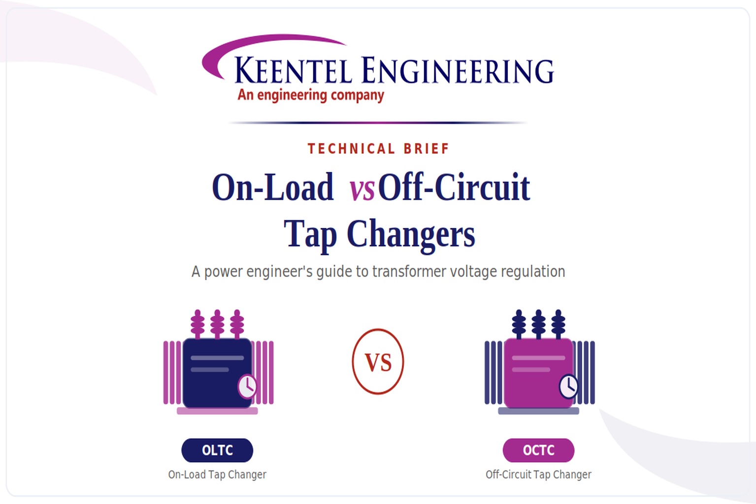
Learn the differences between On-Load and Off-Circuit Tap Changers, including OLTC vs OCTC operation, voltage regulation, IEEE standards, maintenance, and transformer selection.
By SANDIP R PATEL
•
July 28, 2026
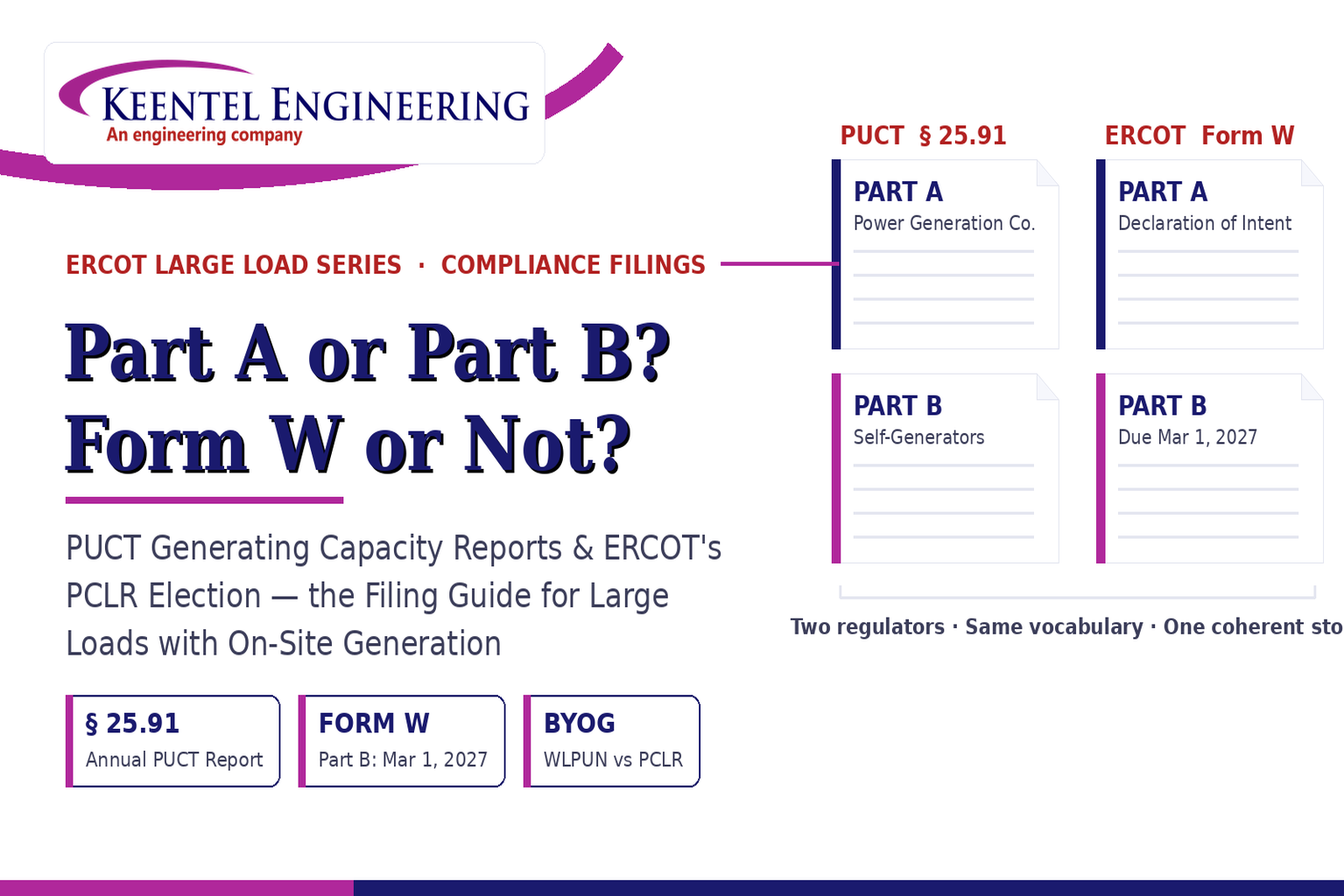
Learn the differences between the PUCT Generating Capacity Report and ERCOT Form W, including Part A vs Part B, PCLR, WLPUN, BYOG projects, and Batch Zero compliance.

By SANDIP R PATEL
•
July 28, 2026
Learn how PGRR144, Batch Zero, and Batch 1 affect ERCOT large-load interconnections, dynamic model requirements, MQT testing, PERC1, and project readiness.

By SANDIP R PATEL
•
July 28, 2026
ERCOT PCLR Batch Zero large-load interconnection pathway
By SANDIP R PATEL
•
July 27, 2026
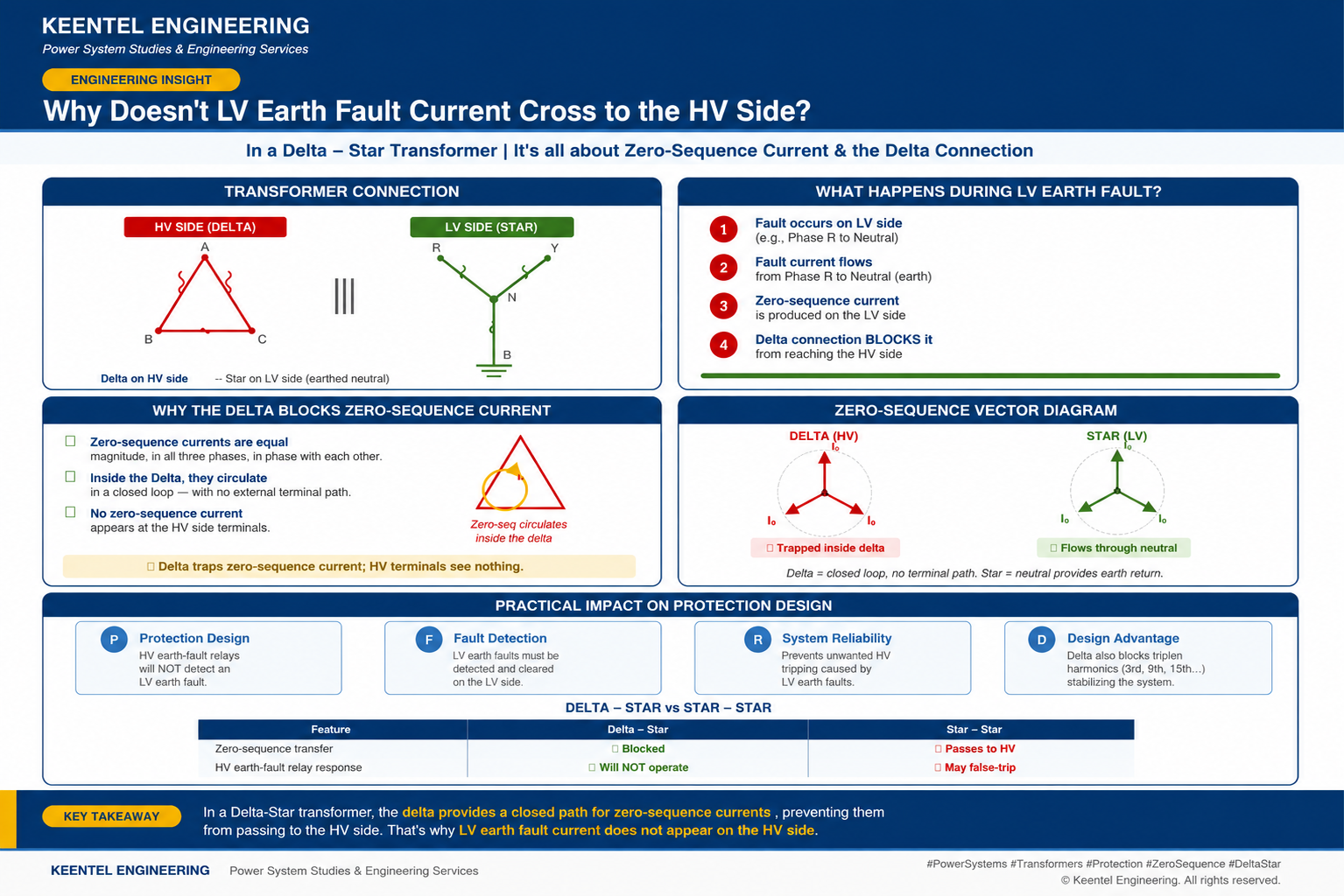
Learn why LV earth-fault current cannot cross a Delta-Star transformer, how zero-sequence current behaves, and what it means for protection design.

By SANDIP R PATEL
•
July 27, 2026
Learn how gas-insulated substations (GIS) improve safety, reliability, and space efficiency with 138 kV design, protection, insulation coordination, and real-world case studies.

By SANDIP R PATEL
•
July 25, 2026
Learn how Class I–IV electrical systems, defence-in-depth, standby and emergency power, DC systems, protection, and load transfer ensure nuclear power plant safety.

By SANDIP R PATEL
•
July 24, 2026
Learn GIS substation safety best practices, SOPs, commissioning, maintenance, interlocking, earthing, and testing to improve grid reliability and uptime.
By SANDIP R PATEL
•
July 23, 2026
Learn how injection and withdrawal studies, 8760 headroom modeling, zero-injection engineering, and SPP HILLGA improve large load grid interconnections