
A Coordinated Electric System Interconnection Review—the utility’s deep-dive on technical and cost impacts of your project.
Challenge: Frequent false tripping using conventional electromechanical relays
Solution: SEL-487E integration with multi-terminal differential protection and dynamic inrush restraint
Result: 90% reduction in false trips, saving over $250,000 in downtime
ERCOT enforces all of the above through simulation, which means your model is your compliance case. The bar is now high:
- Whole-facility scope. The model must represent everything the IT load, the UPS and power conversion, the cooling plant, the protection and control systems in formats compatible with ERCOT's study platforms (PSS/E, PSCAD, TSAT).
- Real control loops, not approximations. Generic textbook representations are unacceptable. The model must capture the actual inner control behavior of your power electronics.
- Hardware-validated converter models. For electronic loads, the PSCAD model must be benchmarked against actual hardware testing including voltage ride-through and subsynchronous response. A model assembled from standard PSCAD library blocks fails by definition, because a generic block has never been tested against your vendor's hardware. The good news: validation is a hardware-type test, so results for a given converter product are reusable across every facility that uses it.
- Format migration. Facilities that previously submitted the older composite load model (CMLD) format must transition to EPRI's PERC1 format.
- Three checkpoints. Models are reviewed before the stability study begins (no model, no study), before each quarterly stability assessment, and for electronic loads one final time before energization, when you must submit as-built models with a documented comparison against the previously studied data and a sworn attestation that the model matches actual field settings. ERCOT's review takes 10 business days, extendable by 20 put it on your critical path.
- A living obligation. Change your technology, controls, or relay settings in a way that affects ride-through including converting a crypto mining site to an AI data center — and you've triggered a new interconnection study, even if your megawatts don't change.
| Parameter | Detail |
|---|---|
| System | 230 kV / 138 kV transmission corridors, wind and wet-snow icing exposure |
| Data basis | 15 years of minute-resolution forced-outage records + regional weather observations |
| Core methods | Event grouping, MVA performance curves, time-to-95%-restore, area outage rate curves, fragility modeling, rerun-history benefits, exceedance and log-domain risk metrics |
| Headline result | ≈85% of maximum resilience benefit at 60% of original capital; worst-event restoration window cut from 11 days to 5 in rerun-history terms |
| Decision supported | Capital portfolio selection; resilience plan filing; post-investment verification framework |
| System / Topic | Governing Standard(s) | What It Controls |
|---|---|---|
| Overall plant electrical distribution | IEEE 141 (Red Book); IEEE 666 | Distribution architecture, voltage selection, design of generating station auxiliary service systems |
| Power system studies | IEEE 399 (Brown Book); IEEE 551 | Load flow, symmetrical/asymmetrical short circuit, motor starting methodologies down to the lowest LV panelboard |
| Protection & coordination | IEEE 242 (Buff Book); IEEE 3004.5; IEEE C37 series | Generator relaying (21, 59N, 87G), time-current coordination, selective clearing between LV and MV tiers |
| GSU / UAT / SST transformers | IEEE C57.12.00 and C57 family | Transformer ratings, impedance, testing, loading |
| HV switchyard breakers | IEEE C37.06 | AC high-voltage circuit breaker preferred ratings |
| MV switchgear (13.8 kV) | IEEE C37.20.2; IEEE C37.20.7 | Metal-clad construction, compartmentalization, vacuum breakers; arc-resistant design with plenum venting |
| MV cable | UL 1072; ICEA S-93-639 (NEMA WC 74) | Type MV-105 shielded cable, 133% insulation level for HRG systems |
| LV switchgear (480 V) | IEEE C37.13; UL 1558 | Metal-enclosed LV power circuit breaker switchgear to 635 V, draw-out ACBs with electronic trip units |
| Motor control centers | UL 845; NEMA ICS 18 | LV-MCC construction, MCCB/MCP protection for motors under ~200 HP |
| Motors | NEMA MG-1 | Motor performance, starting characteristics, service factors |
| DC & battery systems | IEEE 485; IEEE 946 | Lead-acid battery sizing (125/250 VDC), DC auxiliary system design |
| Grounding | IEEE 80; IEEE 142 (Green Book) | Ground grid step/touch potential limits; system grounding including high-resistance grounding |
| Lightning protection | IEEE 998 | Direct-stroke shielding of switchyard and outdoor generator structures |
| Arc flash & electrical safety | IEEE 1584; NFPA 70E | Incident energy calculation; worker safety boundaries and PPE |
| Fire protection | NFPA 850 | Fire protection and risk management for combustion turbine generating plants |
| Installation code | NEC (NFPA 70); NESC | Wiring methods inside the plant fence; overhead/outdoor clearances at the switchyard |
| Interconnection & compliance | FERC LGIP; NERC MOD-025/026/027, PRC-019/024/029, FAC-008 | Interconnection process, model validation, protection/ride-through coordination, facility ratings |
| IFC / Construction Deliverable | Purpose |
|---|---|
| Stamped IFC packages | Legal basis for construction; P.E. responsible charge |
| Final relay settings & TCCs | Protection as-installed matches the coordination study |
| Calculation archive | Owner records; NERC audit evidence trail |
| Commissioning procedures | Safe, sequenced energization; MOD field testing |
| Construction support | RFIs, field changes, FAT/SAT witness |
| As-builts & model handoff | Operating baseline; future study currency |
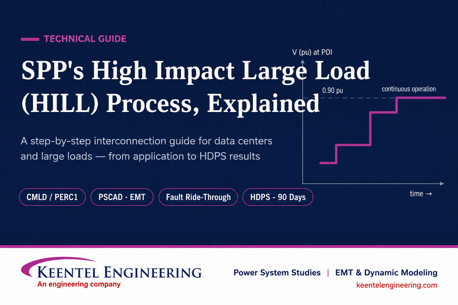
SPP's High Impact Large Load (HILL) Process Explained
Jul 09, 2026 | Blog
By Keentel Engineering — Power System Studies | EMT & Dynamic Modeling | Interconnection Support
AI data centers, crypto mining facilities, hydrogen electrolyzers, and large industrial plants are connecting to the grid at a scale the power industry has never seen. A single AI campus can now demand more power than a mid-size city — and unlike a city, it can appear on the system in 18 months and change its consumption by hundreds of megawatts in seconds.
The Southwest Power Pool (SPP) responded with one of the most comprehensive large-load interconnection frameworks in North America: the High Impact Large Load (HILL) process, established through Revision Request 696 (effective January 15, 2026) and unanimously approved by FERC in January 2026. If you are developing a data center or any large load in the SPP footprint — Kansas, Oklahoma, Nebraska, the Dakotas, and beyond — this process now governs how your project gets studied, what your equipment must be capable of, and what models you must deliver before SPP will run a single simulation.
This guide walks through the entire process step by step, explains the engineering behind each requirement, and answers the technical questions we hear most often from developers, owner's engineers, and EPCs.
Part 1: What Is a HILL?
A HILL is a classification of load defined in the SPP Open Access Transmission Tariff (OATT). Your project is a HILL if it is a new commercial or industrial load — or an increase in load at a single site that meets either threshold:
10 MW or more connected at a voltage of 69 kV or below, or- 50 MW or more connected above 69 kV.
Electric storage resources are excluded from the definition. Virtually every hyperscale or co-location data center, and most AI training campuses, will exceed these thresholds by an order of magnitude.
Why the special treatment?
Because large power-electronic loads behave nothing like the aggregate residential and commercial load the grid was planned around. A 245 MW data center is, electrically, a massive rectifier plant: UPS front ends, server power supplies, and variable-speed cooling drives. During a transmission fault, that entire load can disconnect in a few cycles — and either stay off or slam back on. Uncontrolled tripping of gigawatts of load during a voltage sag can turn a routine fault into a regional frequency and voltage event. SPP's HILL framework exists to make sure that doesn't happen.
Part 2: Choosing Your Pathway Attachment AQ, Attachment AX, or CHILL
Before any study begins, the Transmission Customer (typically the load-serving entity or network customer sponsoring your project) must choose a study pathway. As of RR720 (effective July 1, 2026), customers with sufficient Designated Resources have a choice.
Attachment AQ — the Delivery Point Assessment path.
This is the traditional route, used when the Transmission Customer already has enough Designated Resources (contracted generation) to serve the new load. The HILL is studied through a HILL Delivery Point Study (HDPS) alongside the host Transmission Owner's Load Connection Study.
Attachment AX — the Provisional Load Process.
This newer path addresses the reality that many large loads want service faster than new generation can clear the traditional interconnection queue. Under AX, the HDPS incorporates planned generation identified to serve the load, including a Generator Outlet Facility (GOF) analysis. The load receives provisional service tied to that generation; once the resource obtains firm service through the Aggregate Transmission Service Study, both move to a standard Network Integration Transmission Service Agreement (NITSA). Network upgrade costs are directly assigned to the customer during the provisional period, then migrate to Base Plan funding.
CHILL — Conditional HILL service.
For projects with the most aggressive energization timelines, SPP offers conditional access: quick study results and interconnection in exchange for accepting potential curtailment during periods of system stress.
Co-located generation: HILLGA and HILLGIA.
If your project pairs on-site or near-site generation with the load behind a common point of interconnection (POI) — increasingly the default for AI campuses — SPP's HILL Generation Assessment (HILLGA) process provides an interconnection agreement (HILLGIA) path, with requirements including a POI no more than two substations from the HILL and commercial operation within five years of the study agreement.
How Keentel helps:
Pathway selection is a commercial decision with deep technical consequences. Keentel Engineering supports developers and owner's engineers in evaluating AQ vs. AX vs. CHILL against Designated Resource positions, generation development timelines, and curtailment risk tolerance — before the application is filed, when the decision is still cheap to change.
Part 3: The Application Package What You Must Submit
There is no cluster window or filing deadline. HILL requests are processed on a rolling basis, which means the real "deadline" is self-imposed: the 90-day study clock does not start until your package is complete and validated. An incomplete submittal doesn't get rejected — it just sits, burning schedule.
For an Attachment AQ request, the submittal (sent to SPP's load studies group) must include:
- A fully completed Delivery Point Assessment (DPA) Request Form (Addendum 1 to Attachment AQ).
- A fully executed HDPS Agreement (template on SPP's OASIS studies page).
- A ten-year load forecast with summer, winter, and light-load values for the delivery point, plus any associated changes at other delivery points.
- A one-line diagram showing the anticipated load and changes to local delivery facilities.
- Associated IDEV files (SPP's power-flow model change files).
- The completed Additional HILL Characteristics Form (Business Practice 7850) — the detailed load-behavior questionnaire introduced by RR724.
- Load modeling data — a CMLD and/or PERC1 model, with PERC1 preferred by SPP.
- Any useful supplemental information — and SPP explicitly recommends including a PSCAD model at the time of submission (more on why below).
The Attachment AX list is similar but adds details of the planned generation — location, capacity, and the associated IDEV and DYR (dynamics) files. Under AX, the customer has 30 calendar days after submitting the request form to deliver the executed HDPS Agreement and study deposit.
The item that trips up most projects is #7.
Ten-year forecasts and one-lines are familiar territory. A validated PERC1 or CMLD parameter set that actually represents
your UPS topology, cooling plant, and IT load ramp behavior is specialized power-systems work — and it is now a gating item for the study clock.
Part 4: The HDPS Step by Step
Once the package is complete:
Step 1 — Scoping call (within 10 days).
SPP, the Transmission Customer, and the host Transmission Owner meet to validate the request data, agree on study scope and assumptions, and set the study due date. Data validation at this call is what officially starts the 90-day clock.
Step 2 — The 90-day base study stage.
SPP performs the HDPS while the host TO simultaneously performs its Load Connection Study, and affected-system impacts are screened. The base stage comprises five analyses:
- Thermal overload study. Power-flow analysis under specified contingencies and operating conditions, comparing pre- and post-project loading on transmission equipment to identify overloads and required mitigations.
- Voltage stability study (steady state). Power-flow analysis across dispatch scenarios and contingencies to confirm the load does not cause voltage violations or non-convergent (voltage-collapse) conditions, identifying reactive support needs.
- Short circuit study. Fault-duty analysis per NERC TPL-001-5.1, comparing pre- and post-project fault levels to determine whether breaker or equipment mitigation is needed.
- RMS dynamic performance study. Transient stability analysis using SPP's network model and your RMS load model (this is where your CMLD/PERC1 gets exercised). SPP evaluates frequency response, voltage recovery, transient stability, load tripping and reconnection, ramping, energization, and fault ride-through against the SPP Disturbance Performance Requirements and NERC TPL-001-5.1.
- EMT screening — the SCRCCT gate. SPP screens the POI's system strength using Short Circuit Ratio (SCR), Weighted SCR (WSCR), Composite SCR (CSCR), and Critical Clearing Time (CCT). The thresholds: SCR/WSCR/CSCR ≥ 6.0 and CCT ≥ 0.15 seconds. Fall below either, and your project proceeds to the supplemental stage.
Step 3 — The supplemental study stage (if screening fails).
Here is the schedule trap: supplemental studies are performed outside the 90-day window, and they require a detailed EMT (PSCAD) model of your facility. If you didn't submit one with the application, you now build one while your project waits. This is precisely why SPP recommends — and we insist — that the PSCAD model be part of the original package.
The supplemental stage can include:
- EMT dynamic performance study — detailed electromagnetic-transient simulation of the facility against the transmission network.
- Sub-synchronous oscillation (SSO) screening and detailed studies — impedance frequency scans at the POI per CIGRE Technical Brochure 909, under contingencies up to N-5, checking for sub-synchronous resonance (SSR) and sub-synchronous control interactions (SSCI) between your converters and the network.
- Converter-driven stability studies — screening via SCR and weighted Multi-Infeed Interaction Factor (wMIIF), with detailed EMT analysis of control interactions between your facility, nearby converters, and third-party equipment.
- Emergency power control (EPC) study — verification that the facility's emergency power controls and ramp-rate capability perform as designed, tested against a Thévenin network equivalent.
- Active/reactive power capability and controller studies — confirmation of P/Q capability at the POI and step-response verification of the facility's power controllers.
- Power quality study — harmonic compliance, energization voltage-step limits, and operation under unbalanced conditions.
- Fault ride-through EMT study — direct demonstration of the facility riding through the required voltage/frequency envelopes.
- Network model verification and HILL model verification — SPP checks its own RMS-vs-EMT network consistency, and critically, checks that your RMS and EMT models agree with each other.
Step 4 — Study report and next steps.
SPP delivers the HDPS report within the 90 days (base stage). Results are valid for one year, and the Transmission Customer has one year from posting to notify SPP of intent to add the load to its NITSA (or Provisional Service Agreement under AX).
Part 5: The Fault Ride Through Requirements What Your Facility Must Actually Do
SPP's HILL Fault Ride-Through Requirements are where the framework moves from paperwork to physics. These are binding performance expectations, evaluated through modeling, commissioning tests, and operational monitoring. The highlights:
Voltage ride-through (measured at the POI).
The facility must operate continuously between 0.90 and 1.10 per-unit voltage. It must ride through 0.80–0.90 pu for at least 2.0 seconds, 0.50–0.80 pu for 0.5 seconds, voltages below 0.50 pu for 0.15 seconds, and overvoltage of 1.10–1.20 pu for 0.5 seconds. The envelope is aligned with the ITIC (formerly CBEMA) curve and ERCOT's large electronic load proposal.
Behavior during sags — not just survival.
During shallow sags (0.5–0.8 pu), the load must keep drawing power from the grid, with load reduction proportional to the voltage dip. For deep sags below 0.5 pu, the load may transfer to UPS or trip — but it must return to at least 90% of pre-disturbance consumption within one second of voltage recovering to 0.9 pu. In weak-grid conditions, that recovery time can be extended in consultation with SPP and the TO to avoid post-fault oscillations.
Constant current, not constant power.
Power-electronic loads must use constant-current control during disturbances. Constant-power control is prohibited — because a constant-power load increases its current draw as voltage falls, which is exactly the behavior that deepens sags and drives voltage collapse.
Reclosing ride-through.
Transmission faults are often cleared by breakers that automatically reclose — sometimes into a still-faulted line. Your facility must withstand up to six voltage fault-clearing attempts within a 90-second period before protection-driven disconnection is acceptable.
Transient overvoltage and frequency.
Instantaneous overvoltage withstand follows IEEE 2800-2022 Table 14 (cumulative durations over a one-minute window — e.g., 3 ms above 1.40 pu, 15 ms above 1.20 pu). Frequency ride-through follows a PRC-029-1-based profile: continuous operation from 58.8 to 61.2 Hz, and 299 seconds of ride-through out to 57.0 and 61.8 Hz.
The VSD exemption opportunity.
The requirements include a pragmatic carve-out: variable-speed drives (a large fraction of any data center's cooling plant) may be exempted from the constant-current requirement, the deep-sag minimum duration, and the transient overvoltage requirements — but only if the HDPS demonstrates the exemption will not adversely affect SPP grid reliability. That demonstration is a modeling exercise. Done well, it can meaningfully reduce your equipment specification and compliance cost.
Co-located generation has its own rules.
Inverter-based resources behind the same POI must meet IEEE 2800-2022 Clause 7 (with SPP-specified decision points, including reactive-current priority during faults); synchronous machines follow NERC PRC-024-4.
How Keentel helps:
Keentel performs facility-level FRT gap assessments — comparing your actual UPS transfer settings, VSD behavior, and protection philosophy against the SPP tables
before models are built — and prepares the technical justification for VSD exemptions where the physics supports them. Finding a ride-through gap in Week 1 costs a design memo; finding it in the SPP study report costs a restudy.
Part 6: The Models CMLD, PERC1, and PSCAD
Three models sit at the heart of every HILL submittal, and SPP will formally verify that they agree with each other.
CMLD (Composite Load Model – Dynamic).
The WECC composite load model (CMPLDW) represents the facility as a mix of motor types, electronic load, and static load behind a feeder/transformer equivalent, with protection-based tripping and reconnection. For a data center, the parameterization must capture the electronic (UPS-served) fraction, the VSD-driven cooling fraction, any direct-connected motors, and the trip/reconnect thresholds that mirror the FRT envelope.
PERC1 — SPP's preferred model.
PERC1 is the newer performance-based electronic load model developed through industry load-modeling efforts specifically for power-electronic-dominant facilities. Rather than approximating a data center as a motor mix, PERC1 directly represents the behaviors SPP's FRT requirements are written around: proportional load reduction during sags, constant-current disturbance behavior, deep-sag transfer/trip logic, and the timed recovery ramp. SPP's submittal requirements list load modeling data as "CMLD and/or PERC1 (preferred)" — submitting a well-parameterized PERC1 signals to SPP's study engineers that your team knows the current framework.
PSCAD (EMT).
The electromagnetic-transient model represents the facility at the converter level: UPS rectifier front-ends with their ride-through, transfer, and recovery controls; VSD drive stages; transformers and the collector system; and facility protection logic. Because the supplemental studies exercise this model against Thévenin equivalents, impedance scans, unbalanced faults, energization events, and multi-reclose sequences, the model must be built to a much higher standard than "it runs": stable initialization, flat start, numerical robustness, and validated ride-through behavior.
Model verification is not optional.
SPP's HILL Model Verification study compares the responses of your RMS and EMT models to confirm consistency. If your CMLD/PERC1 and PSCAD models were developed by different parties at different times from different data, discrepancies surface during SPP's study — the most expensive possible moment. The models should be developed as a matched pair and benchmarked before submittal.
A note on PNNL reference models.
Pacific Northwest National Laboratory has published excellent reference models and parameterizations for data center loads, and many projects rightly start there. But reference models represent a generic facility. SPP's process — particularly the FRT validation and model verification steps — requires parameters traceable to your equipment: your UPS topology and transfer settings, your chiller and DLC plant, your block-load ramp rates, your protection settings. Refinement from PNNL baselines to site-specific, SPP-format models is exactly the specialized scope most project teams need help with.
How Keentel helps:
Keentel Engineering develops CMLD and PERC1 parameter sets and PSCAD facility models as a matched, mutually benchmarked pair — validated against the full SPP FRT envelope (voltage sag tables,
IEEE 2800 TOV cumulative-duration logic, frequency profiles, six-reclose sequences, and one-second recovery) and packaged in SPP-submittal formats, including IDEV-compatible records and Business Practice 7850 documentation. We build every PSCAD model supplemental-stage-ready, so a failed SCRCCT screen costs your project analysis time, not model-development time.
Part 7: A Realistic Timeline
For a well-prepared project, the sequence looks like this:
| Phase | Duration | Critical Path Item |
|---|---|---|
| Model development & submittal package assembly | 2–6 weeks | Load model + PSCAD readiness |
| Submittal → scoping call | ~10 days | Complete, validated data |
| HDPS base stage (+ TO Load Connection Study, affected systems) | 90 calendar days | — |
| Supplemental EMT studies (only if SCRCCT screening fails) | Additional months, outside the 90 days | Having a PSCAD model already on file |
| Results validity / NITSA election | 1 year | Commercial decision |
The two levers a developer actually controls are at the top of the table: how fast the package gets complete, and whether the PSCAD model is in it. Everything after that runs on SPP's clock.
Part 8: The Seven Most Common Mistakes We See
- Submitting without load models and assuming SPP will "work with you." The clock simply doesn't start.
- Submitting CMLD only, when SPP prefers PERC1. At best a data-validation comment cycle; at worst, a model that can't represent the required disturbance behaviors.
- Skipping the PSCAD model to save budget. If SCRCCT screening fails at a weak POI — common in load pockets — the project waits months while a model is built.
- Developing RMS and EMT models independently. SPP's model verification study will find the inconsistencies for you.
- Modeling a facility the equipment can't deliver. If the UPS transfer settings or VSD ride-through don't actually meet the FRT tables, a beautiful model just documents non-compliance.
- Ignoring the VSD exemption pathway. Teams over-specify equipment to meet requirements the tariff would have exempted them from — if anyone had run the demonstration.
- Treating the Additional HILL Characteristics Form as paperwork. The form's answers must match the models. Inconsistencies between the form, the forecast, and the model parameters are the fastest route to a deficiency notice.
How Keentel Engineering Supports HILL Projects
Keentel Engineering provides end-to-end dynamic modeling and study support for large load interconnections in SPP and across North American markets:
- CMLD and PERC1 dynamic load model development — site-specific parameterization from your equipment data, benchmarked against reference models (including PNNL baselines), encoded to the SPP FRT envelope, and delivered in SPP submittal formats with Business Practice 7850 documentation.
- PSCAD EMT model development and validation — supplemental-stage-ready facility models covering UPS front-ends, VSD cooling plant, protection and reconnection logic; validated against the full SPP ride-through requirements including reclose sequences, TOV cumulative-duration logic, and recovery performance.
- RMS-vs-EMT model verification — matched-pair benchmarking that pre-satisfies SPP's HILL Model Verification study.
- FRT gap assessments and VSD exemption studies — equipment-versus-requirement gap analysis before model build, and HDPS-basis technical justification for VSD exemptions.
- Submittal package support — Additional HILL Characteristics Form, IDEV files, and coordination of the load forecast data set.
- Study-cycle coordination — scoping call support, SPP/TO comment response, model resubmittals, and on-call engineering through base and supplemental study stages.
- Pathway and strategy advisory — AQ vs. AX vs. CHILL evaluation, co-located generation (HILLGA/HILLGIA) coordination, and weak-grid mitigation planning.
Every engagement is performed under the responsible charge of a licensed Professional Engineer, with mobilization typically within two business days of notice to proceed.
Ready to start — or stuck in a comment cycle?
Contact Keentel Engineering at contact@keentelengineering.com or visit keentelengineering.com to schedule a technical consultation. Bring your one-line and your UPS datasheets; we'll bring the roadmap.
Keentel Engineering — Power System Studies | EMT & Dynamic Modeling | Interconnection Support
This article reflects the SPP HILL framework as of mid-2026, including RR696, RR720, and RR724, the HDPS Overview, and SPP's HILL Fault Ride-Through Requirements (V2.0). SPP's requirements continue to evolve through the stakeholder process; always confirm current requirements against SPP's OASIS studies page and governing documents before submittal.
Frequently Asked Questions
Q1: What exactly triggers the supplemental EMT study stage, and how likely is my project to trigger it?
The trigger is the SCRCCT screening in the base stage: if the short circuit ratio metrics (SCR, WSCR, or CSCR) at your POI fall below 6.0, or the critical clearing time falls below 0.15 seconds, supplemental studies are mandated. Likelihood depends entirely on system strength at your POI relative to your load size. A 245 MW power-electronic load at a rural 115 kV or 161 kV POI in a load pocket has a meaningful probability of failing; the same load at a strong 345 kV hub may pass comfortably. SPP also uses tools like EPRI's grid strength assessment tool for rapid screening, and the WSCR/CSCR methods account for multiple HILLs in an area — meaning a neighbor's project can weaken your screening result. Prudent practice: assume supplemental studies are possible, submit the PSCAD model up front, and ask the TO informally about POI fault duty early in siting.
Q2: What is the practical difference between CMLD and PERC1 for a data center?
CMLD (CMPLDW) was designed to represent a mixed distribution feeder — induction motors of several types, electronic load, and static load. You can approximate a data center with it by pushing the electronic fraction high and tuning the motor blocks to represent cooling, but the electronic-load branch's disturbance behavior is a simplification. PERC1 was purpose-built for power-electronic-dominant loads: it directly parameterizes the sag response (proportional power reduction), the current-limiting behavior, the deep-sag trip/transfer decision, and the timed recovery ramp — the exact behaviors SPP's FRT requirements regulate. For a facility that is 90%+ UPS-served IT load plus VSD cooling, PERC1 both models reality better and maps one-to-one onto the compliance requirements, which is why SPP prefers it.
Q3: Our UPS vendor won't release a PSCAD model. Can we still submit?
Yes — this is one of the most common situations. There are three workable approaches, in descending order of fidelity: (1) obtain the OEM's black-boxed (compiled) PSCAD model under NDA, which protects vendor IP while giving SPP a high-fidelity model; (2) have your modeling consultant develop a generic OEM-representative model of the rectifier front-end and controls from datasheets, ride-through certificates, and factory test data, then validate its terminal behavior against vendor-published curves; (3) use published reference models (e.g., PNNL) re-parameterized to your equipment. Option 2 is the standard fallback and is fully acceptable to SPP when documented — but it adds development and validation effort, which is why model scopes are often quoted with and without OEM data availability.
Q4: What does "constant current control during disturbances" actually mean for my facility, and why is constant power prohibited?
A double-conversion UPS naturally regulates its DC bus to deliver constant power to the IT load. Seen from the grid, constant power means that when voltage sags 20%, current rises 25% to compensate. Multiply that across hundreds of megawatts and dozens of facilities, and a voltage sag becomes self-reinforcing — rising current draw depresses voltage further, which is the mechanism of fast voltage collapse. SPP therefore requires the rectifier front-end to switch to constant-current (or current-limited) operation during disturbances: as voltage falls, power drawn falls proportionally, which is stabilizing. Practically, this is a firmware/control requirement on the UPS front-end, and it's one of the first things to verify with your UPS vendor — and to represent correctly in both the PERC1 and PSCAD models.
Q5: Why must the load recover to 90% within one second of voltage recovery? Our UPS could carry the load longer.
The requirement isn't about protecting your load — it's about protecting the system's supply-demand balance. When 245 MW transfers to batteries during a fault, the grid instantly has 245 MW of excess generation, which accelerates every synchronous machine in the region and raises frequency. If the load stays off (or drifts back over tens of seconds), generators may trip on overfrequency or the system may enter unstable swings. A fast, predictable reconnection — at least 90% of pre-disturbance consumption within one second of voltage reaching 0.9 pu — lets SPP's stability studies rely on the load coming back before frequency excursions grow. Note the flexibility built in: in weak-grid conditions, SPP and the TO can agree to a slower recovery ramp specifically to avoid exciting post-fault oscillations. The right recovery time for your facility is a study outcome, not a guess.
Q6: What does "six fault-clearing attempts within 90 seconds" mean in practice?
Transmission protection commonly uses automatic reclosing: after a fault trips a line, the breaker recloses to test whether the fault (often a lightning flashover) has cleared. If the fault persists, the breaker trips again. Your facility, sitting near that line, experiences a sequence of voltage sags in quick succession. Facility protection schemes that count sags or use cumulative-disturbance logic can lock the plant out after the second or third event — precisely the uncontrolled load-loss behavior SPP is guarding against. The requirement: as long as POI voltage stays within the ride-through envelope, the facility must tolerate at least six such clearing attempts in 90 seconds before protection-driven disconnection is acceptable. Verifying this requires simulating full reclose sequences in EMT — single sags don't reveal cumulative-logic problems.
Q7: We're planning on-site generation (gas turbines / BESS / solar) behind the same POI. How does that change the process?
Substantially, in three ways. First, the generation follows its own requirements: IBRs must comply with IEEE 2800-2022 Clause 7 (with SPP decision points, including reactive-current priority and specified positive/negative-sequence current injection behavior), and synchronous machines follow PRC-024-4 — coordinated with the load's ride-through so the combined facility behaves predictably at the POI. Second, the interconnection path may run through SPP's HILLGA process, producing a HILLGIA — with its own milestones, a five-year commercial-operation requirement, and locational constraints (POI within two substations of the HILL). Third, your models get more complex: the PSCAD model must now capture load-generation control interactions behind the POI, and the supplemental studies (particularly converter-driven stability and SSO) take on added importance. Budget more modeling scope and start the coordination earlier.
Q8: What makes a PSCAD model "SPP-ready"? Ours runs fine on our machine.
Running is table stakes. An SPP-ready HILL model must: initialize cleanly and reach a flat start (no start-up transients contaminating study results); run stably against a Thévenin network equivalent, since many supplemental studies (EPC, FRT, controller verification) test the facility against simplified sources; support impedance/frequency scanning at the POI for SSO screening per CIGRE TB 909; represent unbalanced conditions correctly (single-line-to-ground faults, not just three-phase); execute at reasonable simulation speed for study throughput; be delivered with documentation, snapshot files, and a defined interface bus; and — critically — produce responses consistent with the submitted RMS model, because SPP's HILL Model Verification study explicitly compares the two. Models failing these criteria generate comment cycles that consume weeks each.
Q9: Can we really get VSDs exempted from the ride-through requirements?
Potentially, yes — for three specific requirements: constant-current control, the sub-0.5 pu minimum ride-through duration, and transient overvoltage withstand. VSDs may also use a relaxed recovery criterion (90% within one second, with more flexibility on the path). The condition in every case: the HDPS must demonstrate that the exemption "will not adversely affect the reliability of the SPP grid." That demonstration is sensitivity analysis — modeling the facility with VSDs tripping/behaving per their actual capability, and showing system performance still meets SPP's Disturbance Performance Requirements across the contingency set. Whether it succeeds depends on the VSD fraction of your load, POI strength, and local contingency severity. For a data center where cooling is 15–25% of load, a successful exemption case can avoid specifying exotic drive ride-through hardware across the entire mechanical plant — often a seven-figure capital saving justified by a five-figure study.
Q10: How long does the whole process take, end to end?
If the package is complete at submittal and the POI passes SCRCCT screening: roughly 10 days to the scoping call, 90 calendar days for the HDPS base stage (with the TO's Load Connection Study and affected-system screening run in parallel), then commercial steps — results are valid for one year, and the NITSA election is due within one year of posting. Call it four to five months from complete submittal to actionable study results. If screening fails, add the supplemental EMT stage, which runs outside the 90 days and is heavily dependent on model quality and comment-cycle efficiency — typically several additional months. The two schedule risks a developer controls are model readiness at submittal and model quality during review.
Q11: What data should we start gathering today, before we even engage a modeling consultant?
Start with: facility one-line diagrams (even preliminary); UPS make/model/topology, ratings, and ride-through/transfer settings (request the OEM's ride-through certification and any available dynamic models now — vendor lead times are the long pole); cooling plant equipment lists with VSD data; IT load block sizes, ramp-rate expectations, and phasing plan; protection philosophy and settings; the ten-year load forecast by season; and any prior utility correspondence or screening results. If you have this on day one, a competent modeling team can deliver submittal-ready models in two to four weeks. If the UPS data takes six weeks to extract from the vendor, that's your critical path — not the modeling.
Q12: We already submitted and SPP issued data-validation comments on our load models. Now what?
This is recoverable and common. Triage the comments into categories: format issues (records not in SPP-compatible form — quick fixes), parameterization issues (values inconsistent with the Additional HILL Characteristics Form or physically unreasonable — require re-derivation from equipment data), and capability issues (the model honestly reflects equipment that doesn't meet the FRT requirements — a design conversation, not a modeling one). Respond with a comment-response matrix mapping each SPP comment to a specific model change and its technical basis. Speed matters: the study clock is paused, and every review cycle typically costs two to four weeks. This is also the moment to upgrade a CMLD-only submittal to include PERC1 and a PSCAD model, resolving the current comments and pre-empting the next round.

About the Author:
Sandip "Sonny" R. Patel, P.E.
IEEE Senior Member · Founder & CEO, Keentel Engineering
In 1995, Sonny Patel earned his Electrical Engineering degree from the University of Illinois. But degrees don't build legacies — action does.
For three decades, he has worked the power industry from every side of the table: 16 years as a utility engineer at Exelon/Commonwealth Edison; generation leadership across hydroelectric, industrial steam turbine, and a 9 GW renewable fleet; NERC Regional Entity Senior Compliance Engineer and Audit Team Lead, auditing some of the nation's largest utilities; and testing and commissioning lead on equipment up to 765 kV — the very top of the North American grid.Utility. Generator. Regulator. Consultant. Few engineers have seen all four seats. Fewer still have sat in them.
His experience spans nuclear, hydro, conventional generation, renewables, oil and gas, mining — and today's data centers, where he is authoring a three-book series on data center design. He is a Licensed Professional Engineer in six states and a Licensed Electrical Contractor in Florida (Unlimited EC) — he doesn't just design the work; he's qualified to stand behind its execution.Today, as Founder and CEO of Keentel Engineering, Sonny leads a nationwide team of engineers delivering substation design, power system studies, NERC compliance, and commissioning — done right, coast to coast.Three decades. Every side of the table. One standard: accountable engineering.
Services

Let's Discuss Your Project
Let's book a call to discuss your electrical engineering project that we can help you with.
About the Author:
Sandip "Sonny" R. Patel, P.E.
IEEE Senior Member · Founder & CEO, Keentel Engineering
In 1995, Sonny Patel earned his Electrical Engineering degree from the University of Illinois. But degrees don't build legacies — action does.
For three decades, he has worked the power industry from every side of the table: 16 years as a utility engineer at Exelon/Commonwealth Edison; generation leadership across hydroelectric, industrial steam turbine, and a 9 GW renewable fleet; NERC Regional Entity Senior Compliance Engineer and Audit Team Lead, auditing some of the nation's largest utilities; and testing and commissioning lead on equipment up to 765 kV — the very top of the North American grid.
Utility. Generator. Regulator. Consultant. Few engineers have seen all four seats. Fewer still have sat in them.
His experience spans nuclear, hydro, conventional generation, renewables, oil and gas, mining — and today's data centers, where he is authoring a three-book series on data center design. He is a Licensed Professional Engineer in six states and a Licensed Electrical Contractor in Florida (Unlimited EC) — he doesn't just design the work; he's qualified to stand behind its execution.
Today, as Founder and CEO of Keentel Engineering, Sonny leads a nationwide team of engineers delivering substation design, power system studies, NERC compliance, and commissioning — done right, coast to coast.Three decades. Every side of the table. One standard: accountable engineering.
Leave a Comment
Thank you for contacting us.
We will get back to you as soon as possible.
We will get back to you as soon as possible.
Oops, there was an error sending your message.
Please try again later.
Please try again later.
Related Posts

By SANDIP R PATEL
•
October 3, 2026
Engineering guide to PRC-028 disturbance recording, PRC-029 ride-through and PRC-030 event detection for inverter-based resources.

By SANDIP R PATEL
•
October 3, 2026
A practical guide to SSO classification, SSR, PEDI, Wind-SSCI, EMT analysis, mitigation and protection based on CIGRE TB 909.

By SANDIP R PATEL
•
October 6, 2026
Learn ERCOT generator testing for PFR, MOD-025 and MOD-026/027, including staged tests, capability verification, dynamic models and field testing.

By SANDIP R PATEL
•
October 3, 2026
Learn how PV string I-V curve testing identifies hidden solar performance losses, including soiling, shading, mismatch, degradation, and wiring faults.

By SANDIP R PATEL
•
October 3, 2026
Learn how active harmonic filters work, how to size AHF systems, reduce VFD harmonics, calculate losses, and meet IEEE 519 TDD limits at the PCC.
By SANDIP R PATEL
•
October 3, 2026
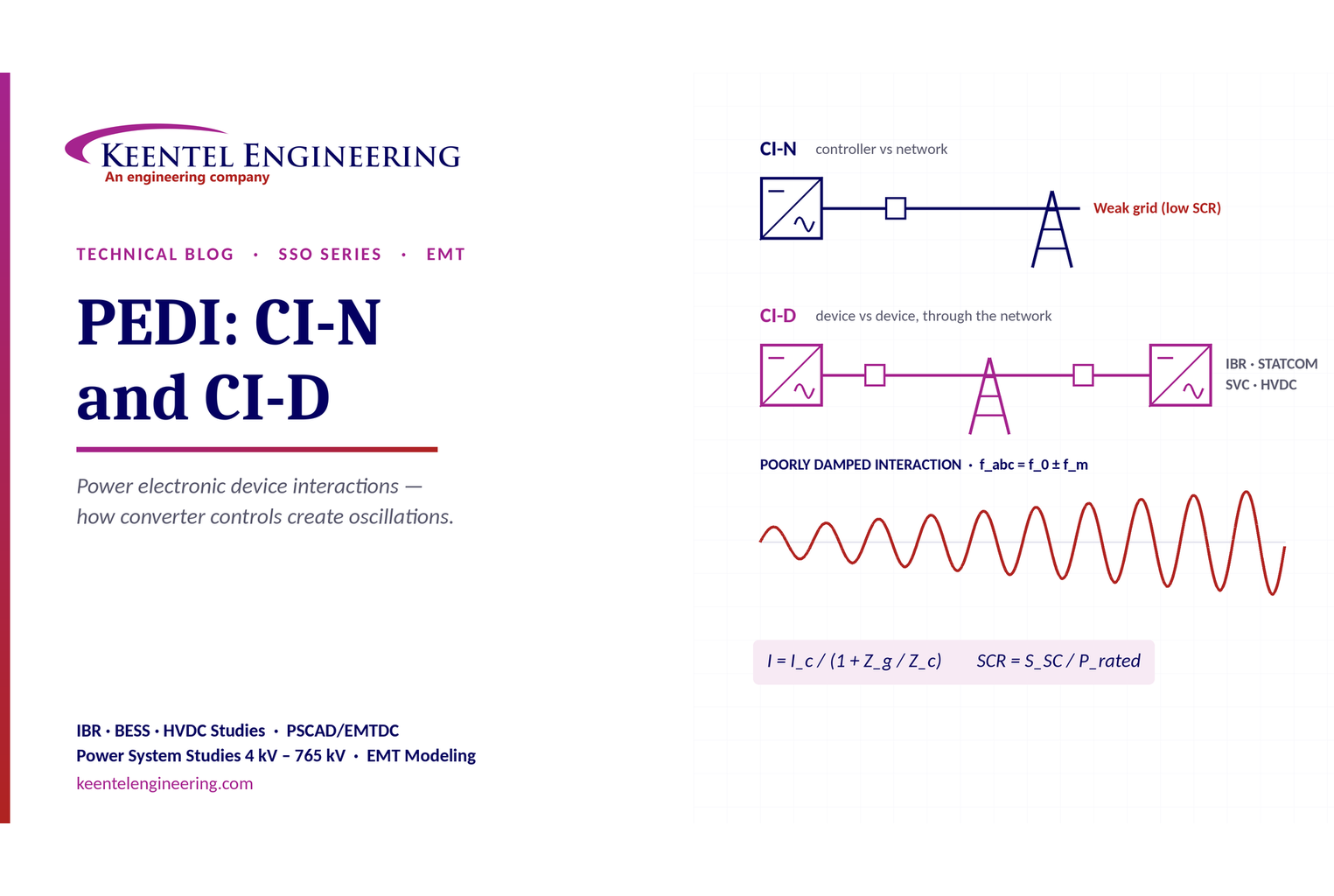
Learn power electronic device interactions (PEDI), including CI-N and CI-D, weak-grid stability, SCR, EMT studies, impedance analysis and mitigation for IBRs.
By SANDIP R PATEL
•
October 3, 2026
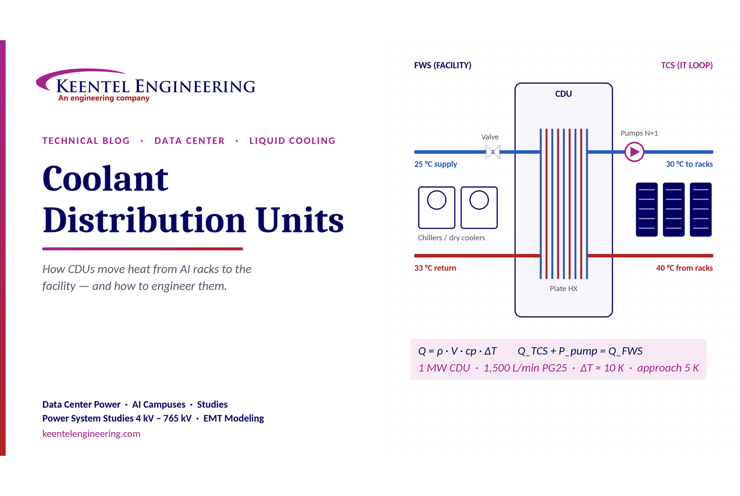
Learn how data center coolant distribution units (CDUs) work, including FWS and TCS loops, heat transfer, sizing, redundancy and liquid cooling for AI data centers.
By SANDIP R PATEL
•
October 3, 2026
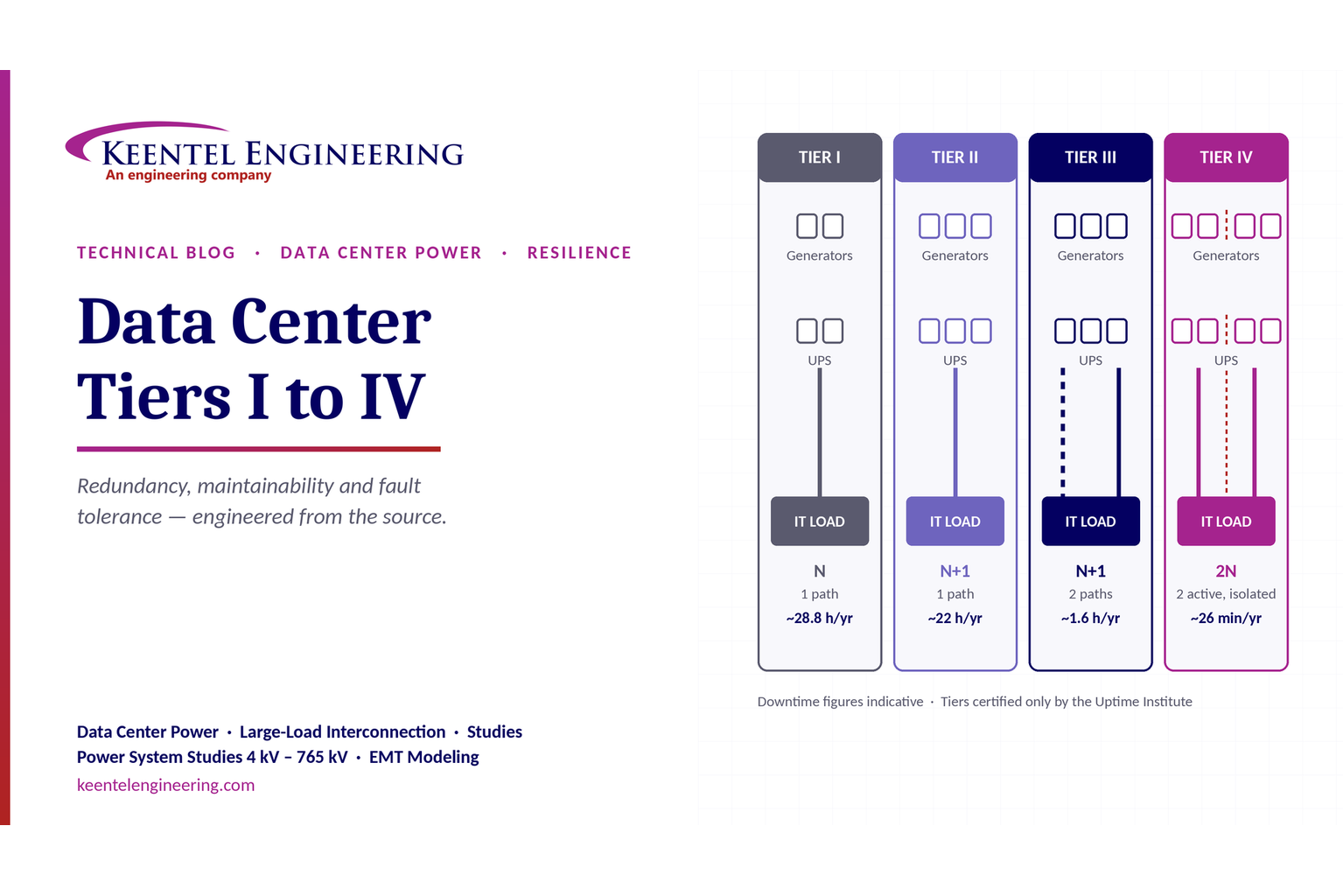
Compare Data Center Tiers I–IV, including redundancy, uptime, Tier III concurrent maintainability, Tier IV fault tolerance, UPS, generators and power design.

By SANDIP R PATEL
•
October 3, 2026
Learn how BESS supports grid stability through fast frequency response, voltage support, oscillation damping, black start, grid-forming controls and EMT studies.





