
A Coordinated Electric System Interconnection Review—the utility’s deep-dive on technical and cost impacts of your project.
Challenge: Frequent false tripping using conventional electromechanical relays
Solution: SEL-487E integration with multi-terminal differential protection and dynamic inrush restraint
Result: 90% reduction in false trips, saving over $250,000 in downtime
ERCOT enforces all of the above through simulation, which means your model is your compliance case. The bar is now high:
- Whole-facility scope. The model must represent everything the IT load, the UPS and power conversion, the cooling plant, the protection and control systems in formats compatible with ERCOT's study platforms (PSS/E, PSCAD, TSAT).
- Real control loops, not approximations. Generic textbook representations are unacceptable. The model must capture the actual inner control behavior of your power electronics.
- Hardware-validated converter models. For electronic loads, the PSCAD model must be benchmarked against actual hardware testing including voltage ride-through and subsynchronous response. A model assembled from standard PSCAD library blocks fails by definition, because a generic block has never been tested against your vendor's hardware. The good news: validation is a hardware-type test, so results for a given converter product are reusable across every facility that uses it.
- Format migration. Facilities that previously submitted the older composite load model (CMLD) format must transition to EPRI's PERC1 format.
- Three checkpoints. Models are reviewed before the stability study begins (no model, no study), before each quarterly stability assessment, and for electronic loads one final time before energization, when you must submit as-built models with a documented comparison against the previously studied data and a sworn attestation that the model matches actual field settings. ERCOT's review takes 10 business days, extendable by 20 put it on your critical path.
- A living obligation. Change your technology, controls, or relay settings in a way that affects ride-through including converting a crypto mining site to an AI data center — and you've triggered a new interconnection study, even if your megawatts don't change.
| Parameter | Detail |
|---|---|
| System | 230 kV / 138 kV transmission corridors, wind and wet-snow icing exposure |
| Data basis | 15 years of minute-resolution forced-outage records + regional weather observations |
| Core methods | Event grouping, MVA performance curves, time-to-95%-restore, area outage rate curves, fragility modeling, rerun-history benefits, exceedance and log-domain risk metrics |
| Headline result | ≈85% of maximum resilience benefit at 60% of original capital; worst-event restoration window cut from 11 days to 5 in rerun-history terms |
| Decision supported | Capital portfolio selection; resilience plan filing; post-investment verification framework |
| System / Topic | Governing Standard(s) | What It Controls |
|---|---|---|
| Overall plant electrical distribution | IEEE 141 (Red Book); IEEE 666 | Distribution architecture, voltage selection, design of generating station auxiliary service systems |
| Power system studies | IEEE 399 (Brown Book); IEEE 551 | Load flow, symmetrical/asymmetrical short circuit, motor starting methodologies down to the lowest LV panelboard |
| Protection & coordination | IEEE 242 (Buff Book); IEEE 3004.5; IEEE C37 series | Generator relaying (21, 59N, 87G), time-current coordination, selective clearing between LV and MV tiers |
| GSU / UAT / SST transformers | IEEE C57.12.00 and C57 family | Transformer ratings, impedance, testing, loading |
| HV switchyard breakers | IEEE C37.06 | AC high-voltage circuit breaker preferred ratings |
| MV switchgear (13.8 kV) | IEEE C37.20.2; IEEE C37.20.7 | Metal-clad construction, compartmentalization, vacuum breakers; arc-resistant design with plenum venting |
| MV cable | UL 1072; ICEA S-93-639 (NEMA WC 74) | Type MV-105 shielded cable, 133% insulation level for HRG systems |
| LV switchgear (480 V) | IEEE C37.13; UL 1558 | Metal-enclosed LV power circuit breaker switchgear to 635 V, draw-out ACBs with electronic trip units |
| Motor control centers | UL 845; NEMA ICS 18 | LV-MCC construction, MCCB/MCP protection for motors under ~200 HP |
| Motors | NEMA MG-1 | Motor performance, starting characteristics, service factors |
| DC & battery systems | IEEE 485; IEEE 946 | Lead-acid battery sizing (125/250 VDC), DC auxiliary system design |
| Grounding | IEEE 80; IEEE 142 (Green Book) | Ground grid step/touch potential limits; system grounding including high-resistance grounding |
| Lightning protection | IEEE 998 | Direct-stroke shielding of switchyard and outdoor generator structures |
| Arc flash & electrical safety | IEEE 1584; NFPA 70E | Incident energy calculation; worker safety boundaries and PPE |
| Fire protection | NFPA 850 | Fire protection and risk management for combustion turbine generating plants |
| Installation code | NEC (NFPA 70); NESC | Wiring methods inside the plant fence; overhead/outdoor clearances at the switchyard |
| Interconnection & compliance | FERC LGIP; NERC MOD-025/026/027, PRC-019/024/029, FAC-008 | Interconnection process, model validation, protection/ride-through coordination, facility ratings |
| IFC / Construction Deliverable | Purpose |
|---|---|
| Stamped IFC packages | Legal basis for construction; P.E. responsible charge |
| Final relay settings & TCCs | Protection as-installed matches the coordination study |
| Calculation archive | Owner records; NERC audit evidence trail |
| Commissioning procedures | Safe, sequenced energization; MOD field testing |
| Construction support | RFIs, field changes, FAT/SAT witness |
| As-builts & model handoff | Operating baseline; future study currency |
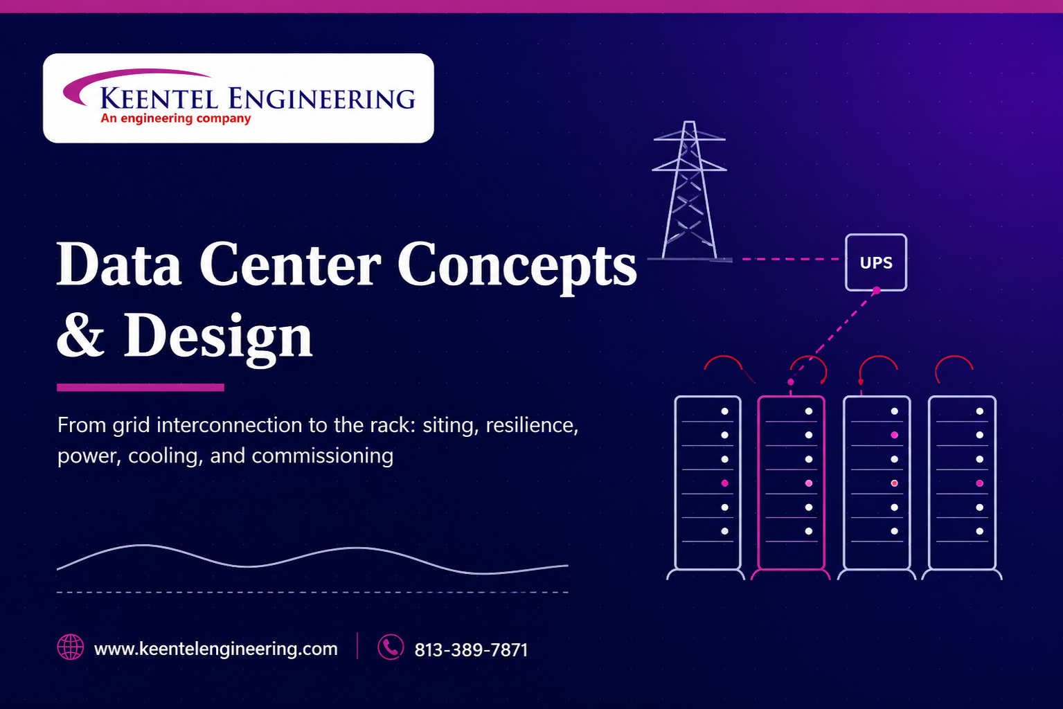
Data Center Concepts and Design From Grid Interconnection to the Rack
Jul 11, 2026 | Blog
Executive Overview
This content package presents Keentel Engineering's integrated perspective on data center concepts and design, organized in three parts. A long-form technical blog walks the complete design chain: what a data center functionally is; site selection in a power-constrained market; resilience philosophy and topology selection; electrical systems from the utility intake through UPS, generation, and rack distribution; mechanical and cooling systems; air and thermal management; energy, PUE, and the widening sustainability ledger; fire safety; network and physical security; commissioning through integrated systems testing; operational governance; and the industry's trajectory under AI-scale demand. A practitioner FAQ addresses the fifteen questions developers, enterprises, and operators raise most often. Three anonymized case studies then demonstrate the approach on representative project archetypes: a hyperscale AI campus interconnection, an enterprise commissioning rescue, and a high-density liquid-cooling retrofit in a live legacy facility.
The unifying thesis: the data center industry's binding constraint has moved outside the building. Power availability, interconnection timelines, large-load reliability obligations, and grid-interactive load behavior now pace projects more than any construction trade — which makes utility-grade power engineering, applied on both sides of the meter as one system, the discipline that determines whether a data center project succeeds and on what schedule.
A data center is a building wrapped around an electrical system. Every other discipline — cooling, fire protection, security, networking, controls — exists to keep conditioned, uninterrupted, high-quality power flowing into IT equipment whose failure the business cannot tolerate. That framing matters because it determines where design risk actually concentrates: not in the architecture, not even primarily in the mechanical plant, but in the power chain that begins at the utility point of interconnection and ends at the server power supply. In the current market — where individual AI training halls request more power than small cities and utility interconnection queues stretch for years — the grid end of that chain has become the single largest determinant of whether a data center project succeeds, and on what schedule.
Keentel Engineering works this problem from both ends: as power systems and interconnection engineers who take large loads through utility and regional reliability processes, and as electrical design engineers who carry the campus from the intake substation through the UPS to the rack. This article lays out the complete design chain for a modern data center — siting, resilience philosophy, electrical and mechanical systems, air and thermal management, fire safety, commissioning, and operations — with particular attention to the decisions that are hardest to reverse later.
1. What a Data Center Actually Is: The Functional Anatomy
Strip away the vendor language and every data center resolves into the same functional blocks. A secure envelope encloses one or more data halls of IT cabinets. Utility power enters through an intake substation, flows through medium- and low-voltage switchgear, is conditioned and bridged by uninterruptible power supply (UPS) systems, backed by standby generation, and delivered to racks through power distribution units (PDUs), busway, or rack power panels. Heat leaves through a cooling chain — room or row-level air handlers, chilled water or refrigerant loops, and external heat rejection — sized to remove essentially every watt the electrical system delivers. Around this core sit the support spaces: plant rooms, battery rooms, network intake rooms at diverse building entries, loading and build/test areas, a network operations center, and the security layers that control movement among them all.
Rack power density is the design variable that drives everything else. Legacy enterprise cabinets at 2–5 kW, virtualized and blade environments at 8–15 kW, dense compute at 20–40 kW, and current-generation AI training racks at 80–150 kW and climbing represent fundamentally different electrical distribution, cooling, and structural problems — not scaled versions of one problem. A hall designed for uniform 8 kW air-cooled racks cannot absorb a 120 kW liquid-cooled AI pod without touching the power chain, the cooling topology, the floor loading, and often the utility supply itself. Because IT refreshes every two to five years while the building and plant last decades, the highest-value design decision is the one that keeps density growth from becoming a rebuild: oversized risers and containment routes, plant rooms with expansion positions, electrical architectures that scale in modules, and a site with secured headroom at the point of interconnection.
2. Site Selection: Power Availability Is the New Location
Traditional site-selection criteria fiber diversity, latency to markets, climate for free cooling, geotechnical and flood risk, planning environment, aviation and security exclusions, workforce access all still apply. But the ordering has changed. In today's market, the availability, schedule, and firmness of utility power is the first filter, and it eliminates more candidate sites than every other criterion combined. Interconnection of a large load is no longer a service application; it is a multi-year engineering and regulatory process involving utility system impact studies, potential network upgrades, contribution-to-cost allocations, and increasingly regional reliability requirements aimed specifically at large loads, including ride-through expectations, telemetry obligations, and curtailment provisions.
- Power due diligence Interrogate the utility early and quantitatively: available capacity at nearby transmission and distribution nodes, study queue position and timelines, upgrade scope and cost exposure, and the utility's posture on phased energization.
- Climate and water Climate drives operating cost through free-cooling hours and water availability; both are now board-level issues as water-use effectiveness joins PUE in sustainability reporting.
- Connectivity Dual diverse fiber entries, carrier presence, and latency or synchronous-replication distance to paired facilities constrain the shortlist further.
- Planning risk Noise (nighttime plant and generator testing), fuel storage volumes, visual massing, and traffic are the recurring planning friction points; early pre-application engagement measurably shortens determination.
- Risk analysis A formal risk schedule external threats, environmental exposures, utility futures, EMI sources, expansion capability compiled with all stakeholders and carried through design is the discipline that keeps siting decisions defensible.
The Keentel view
We treat the interconnection study and the site decision as one workstream. A site with land, fiber, and water but a five-year power timeline is not a site; it is an option. Quantifying that timeline with utility engagement, load-flow screening, and a realistic upgrade scope before land commitment is the cheapest risk mitigation available in data center development.
3. Resilience Philosophy: Choosing a Topology Before Choosing Equipment
Resilience language is standardized around a simple vocabulary. N is the capacity required to serve the load. N+1 adds redundant components so any single unit can fail or be maintained. A concurrently maintainable design allows any component or distribution path to be taken out of service, planned, without interrupting the critical load which forces dual paths at least in alternate form. A fault-tolerant design withstands any single unplanned failure, anywhere, without load interruption which forces two simultaneously active paths (2N or 2(N+1)) and compartmentalization so one event cannot take both. The industry tier framework (Tier I through IV) maps onto exactly these distinctions: single path; single path with redundant components; concurrently maintainable; fault tolerant.
The essential discipline is that a tier level is a business decision expressed in engineering, not an engineering aspiration. Fault tolerance roughly doubles the electrical plant, expands space and cost accordingly, and imposes operating complexity that must be staffed and maintained for decades. A facility serving genuinely continuous, intolerant workloads earns that cost; a facility whose workloads can migrate or tolerate structured maintenance windows does not. Distributed-redundant and block-redundant architectures occupy the middle ground, sharing reserve capacity across systems to approach dual-path availability at lower plant count. What is not acceptable is ambiguity: the resilience level must be declared in the brief, because it drives planning consent, space program, utility capacity, cost, and commissioning scope from day one and mixed halls (a 2N hall and an N+1 hall in one building) are legitimate and increasingly common, provided the boundaries are explicit.
4. Electrical Systems: The Spine of the Facility
4.1 From the intake down
Design proceeds top-down from the utility supply: voltage level, capacity and growth terms, metering point, and on-site substation scope are negotiated with the utility and frequently pace the entire program, since transmission-voltage interconnections for large campuses involve utility-grade substation engineering — bus configurations, protection and relaying, revenue metering, SCADA/RTU telemetry to the utility — that is precisely conventional power engineering, not building services. From there, medium-voltage switchgear architecture (main-tie-main, ring, or breaker-and-a-half at the largest campuses), transformation to utilization voltage using cast-resin or ester-filled units, and low-voltage switchgear rated for the fault duty and arc-flash requirements of very large busses complete the distribution frame. Busbar ratings, breaker interrupting duties, and selective coordination across the entire chain must be proven by short-circuit, coordination, and arc-flash studies — the same study discipline Keentel applies on utility systems, applied inside the fence.
4.2 UPS, energy storage, and standby generation
The UPS bridges the gap between a utility disturbance and generator assumption of load, while continuously conditioning power quality against sags, swells, and harmonics. Static (double-conversion) UPS with lithium-ion or advanced lead batteries dominates new construction, with modern units offering high-efficiency eco or dynamic modes that materially move facility PUE. Rotary and diesel-rotary (DRUPS) machines remain compelling at large unit sizes for their ride-through physics and fault-current contribution, at the cost of mechanical maintenance regimes. Configuration — N+1 within a system, 2N across systems, or distributed redundant — must mirror the declared resilience topology, and neutral-earthing arrangements across UPS, bypass, and generator operating modes require deliberate design: three- versus four-pole switching decisions made casually at design time surface later as nuisance trips, circulating neutral currents, or unsafe isolation conditions.
Standby generation is sized not just for the IT load but for the mechanical plant that must restart with it, with starting-sequence studies proving the block-load and motor-starting behavior. Fuel storage sizing (commonly 24–72 hours at full load), fuel polishing and refill logistics, emissions permitting, and — increasingly — the question of whether the generation asset can provide grid services or operate on renewable diesel are all design-stage decisions. The final meters of the chain — PDUs with static transfer switches, busway with tap-off units, rack power panels, dual-corded IT with A/B feeds — determine whether the facility's theoretical redundancy actually survives at the rack, and single-corded legacy equipment quietly defeats dual-path architectures unless caught by point-of-use transfer switches.
4.3 Monitoring and controls
A modern facility carries an electrical power monitoring system (EPMS/SCADA) over the switchgear, UPS, and generation; a building management system (BMS) over the mechanical plant; and increasingly a data center infrastructure management (DCIM) layer correlating both against IT load at the rack. Designing these as one instrumented architecture — consistent naming, synchronized time, a single alarm philosophy, sub-metering granularity that supports both PUE reporting and capacity management — is dramatically cheaper than reconciling three vendor silos after energization. The same discipline Keentel applies to substation SCADA points lists applies here verbatim.
5. Mechanical Systems: Cooling as a Chain, Not a Component
Cooling design begins with the environmental envelope. Modern IT hardware tolerates supply air across a wide band — the industry-consensus recommended range extends to 27 °C at the rack inlet and allowable ranges reach considerably higher — and every degree of supply-air setpoint increase expands free-cooling hours and refrigeration efficiency. The constraints are legacy hardware that cannot tolerate the modern envelope (and must be zoned for, not designed around), humidity limits that modern equipment has relaxed substantially, rate-of-change limits, and — critically — the thermal ride-through question: at higher setpoints, the time between a cooling failure and IT inlet over-temperature shrinks, so the failure scenario, continuous-cooling provisions (UPS-backed fans and pumps, chilled-water buffer vessels), and rate-of-rise analysis must be engineered as deliberately as the steady state.
System selection then follows density and scale. Perimeter CRAC/CRAH units with underfloor supply serve conventional air-cooled halls; in-row and rear-door heat exchangers extend air cooling into the 20–40 kW band; and above that, liquid arrives — direct-to-chip cold plates handling the majority of rack heat with an air-cooled residual, or immersion for the densest and most specialized deployments. The chilled-water plant behind these choices carries its own resilience design: N+1 or better chillers and economizers, buffer vessels sized for compressor-restart ride-through, dual risers and valved sectionalizing so any unit or pipe segment can be maintained concurrently, and free-cooling economizers — air-side, water-side, or adiabatic-assisted — that in temperate climates now carry the majority of annual cooling hours.
Electronically commutated fans, floor-void pressure control, and variable-speed pumping close the loop on part-load efficiency, which matters because facilities spend years below design load, and plant that only performs at nameplate wastes energy through the entire fill-up curve.
6. Air Management: The Cheapest Megawatt in the Building
In an air-cooled hall, the gap between installed cooling capacity and delivered cooling capacity is almost entirely an air management problem. Two loss mechanisms dominate. Bypass is conditioned air that returns to the cooling units without passing through IT equipment — leaking through cable cutouts, unsealed floor penetrations, and oversupplied grilles. Recirculation is IT exhaust that re-enters IT inlets — over the tops of rows, around row ends, through empty rack positions missing blanking panels. Bypass wastes fan energy and starves the hall; recirculation creates the hot spots that pressure operators into lowering setpoints, which destroys efficiency across the whole facility. It is entirely typical for a legacy hall to circulate twice the airflow its IT load requires and still run hot in the wrong places.
The remedies are physical segregation and measurement. Hot-aisle or cold-aisle containment, rack chimneys, blanking panels, brush-sealed penetrations, and balanced floor grilles convert the hall from a mixing volume into a ducted system; computational fluid dynamics (CFD) modeling validates layouts before racks land and diagnoses problems after; and inlet-temperature instrumentation at the rack face — not just at the cooling unit return — provides the control signal that lets setpoints rise safely. Containment interacts with fire protection (detection and suppression coverage inside contained aisles must be engineered, not assumed) and with occupational limits on hot-aisle working temperatures. Air management does not save energy by itself; it is the enabler that unlocks higher setpoints, lower fan volumes, and free cooling — which is why it is the highest-return retrofit in almost every legacy facility we assess.
7. Energy, PUE, and the Sustainability Ledger
Power usage effectiveness — total facility energy divided by IT energy, as an annualized value — remains the industry's shorthand metric. Legacy facilities commonly ran at 2.0 and above, dominated by compressor energy; current best-practice designs deliver 1.2–1.4, and free-cooling-led architectures in favorable climates press toward 1.1. The strategy stack is hierarchical and interdependent: rationalize and utilize the IT itself (the only watts that do revenue-bearing work); manage air so setpoints can rise; raise setpoints so refrigeration works less and economizers work more; strip electrical losses (high-efficiency UPS modes, right-loaded transformers — including amorphous-core units that cut no-load losses dramatically in the lightly-loaded redundant configurations data centers force — and LED lighting on controls); and only then consider supply-side measures such as on-site generation, heat recovery to district or campus users, and renewable procurement. PUE is also widely misused: it fluctuates with IT load and climate, reaches design value only at design load, and says nothing about water or carbon — so mature operators now report PUE alongside water usage effectiveness and carbon intensity, and increasingly against embodied-carbon assessments of the M&E plant itself, which typically exceeds the building structure's embodied footprint.
8. Fire Safety: Strategy First, Systems Second
Data center fire engineering starts with a documented strategy — business criticality, compliance basis, evacuation, smoke control, firefighting access, and protection philosophy — agreed among the operator, insurer, and authorities before systems are selected, because the systems are only the strategy's instruments. Detection in critical spaces is built on aspirating smoke detection (ASD/VESDA-class): networks of sampling pipes drawing air continuously to laser detectors sensitive enough to alarm at the incipient, pre-visible stage, positioned with the airflow (including in the return path to cooling units) rather than against a static ceiling assumption. Analogue addressable panels provide the per-device status and location precision the risk demands, and the entire response logic — first-knock investigation alarms, second-knock actions, air-handling shutdowns, damper closures, door releases, suppression release — is captured in a cause-and-effect matrix that is tested line-by-line at commissioning and after every subsequent change.
Suppression is layered. Pre-action sprinklers (dry pipes, water admitted only on independent detection) protect the building risk while making accidental discharge into live halls a two-failure event. Clean-agent gaseous systems (inert blends or fluoroketone agents) protect hall volumes without conductive residue — with design attention to room integrity testing, pressure relief venting, post-discharge purge, and the acoustic effect of discharge nozzles on hard drives, which is a real and documented failure mode addressed by low-noise nozzle design. Water mist suits generator and plant rooms; oxygen-reduction (hypoxic) systems, which hold the protected volume below combustion-supporting oxygen levels continuously, have matured into a credible prevention option for lights-out spaces. Containment changes all of it: a contained aisle is a separate compartment from the detection and suppression system's point of view, and retrofitting containment without re-engineering fire protection is a recurring and serious audit finding.
9. Network and Security: The Other Two Utilities
Network provision follows the same resilience logic as power: diverse building entries into physically separated intake rooms, carrier and route diversity verified to the street (not just contractually asserted), structured cabling engineered to current fiber and copper standards with containment, bend-radius, and capacity headroom for growth, and a core/distribution/access architecture that can absorb speed generations without recabling. Physical security is engineered in concentric layers — perimeter fence and PIDS, vehicle interlocks and crash-rated gates, gatehouse and lobby procedures, mantrap or interlocked corridor entries, and data hall access on multi-factor credentials with anti-tailgating measures — each layer instrumented with surveillance positioned to identify rather than merely observe. The design principle is that security, like resilience, is a documented threat-and-risk posture expressed in construction, and the loading bay — the one place where the perimeter deliberately opens — deserves the most careful interlock design in the building.
10. Commissioning and Completion: Where Paper Resilience Becomes Real
A data center's reliability is not designed in; it is proven in. The completion phase is structured as a five-level progression: factory acceptance tests on major plant (witnessed, at full and part load); installation verification by contractors; witnessed component and system demonstrations to the owner's team; inter-system interface testing — UPS to generator to BMS to fire cause-and-effect — proving the control logic among systems; and finally integrated systems testing (IST), the choreographed demonstration that the whole facility rides through every credible failure scenario at load, typically against heat-bank load simulating the IT. The black-building test — deliberately opening the utility supply and watching the facility carry itself — is the graduation exercise. IST is scheduled first and defended absolutely, because it is the only phase that ever gets compressed when construction slips, and every uncommissioned failure mode is simply an outage on deferral.
Completion management wraps the testing in evidence: a commissioning plan with defined key deliverables, a roles-and-responsibilities matrix across owner, contractors, and commissioning agent, test documentation packs, O&M manuals with plant replacement strategies, as-built records, clinical-clean certification of halls before IT wiring, operator training with proof of competency, and soft-landings support through the first operating seasons. The deliverable is not a certificate; it is an operations team that has already seen the facility fail safely, on purpose, before the business moved in.
11. Operations: Engineering the Decades After Handover
The disciplines that keep a commissioned facility at its designed availability are procedural, and they decay without governance. Change management treats every add, move, and maintenance activity in the critical envelope as a controlled event with method statements and approvals. Capacity management gates every new rack against measured — not nameplate — power and cooling headroom, preventing the slow accretion of hot spots and stranded capacity.
Environmental monitoring holds the hall to its envelope continuously; emergency operating procedures are drilled as walk-throughs until the night shift can execute them from memory; escalation paths are documented from first detection through business-continuity notification; and cable hygiene under floors and in containment is enforced so that the airflow paths and spare pathways the design assumed still exist in year twelve. Facilities of identical design diverge in availability over a decade almost entirely on the strength of these procedures — which is why operational readiness belongs in the design scope, not after it.
12. Where the Industry Is Going — and Why It Leads Back to the Grid
Every current trend line points the same direction. AI-class racks have pushed hall densities past what air can carry, making direct-to-chip liquid cooling standard in new high-performance builds and hybrid air/liquid halls the transitional norm. Higher IT thermal tolerance and better air management have pushed PUE toward its practical floor, moving the sustainability frontier to water, embodied carbon, and heat reuse. Modular and phased construction lets infrastructure follow load instead of preceding it by years. And facility scale has grown to the point where individual campuses are transmission-system events: hundreds of megawatts to gigawatts, drawing regional reliability attention, ride-through and telemetry requirements, curtailment frameworks, and interconnection study queues that now pace the industry more than any construction trade. Emerging supply-side options — on-site fuel cells, gas turbines with heat recovery, storage participating in grid markets, and eventually small modular reactors — are all, at bottom, grid-interconnection engineering problems wearing a real-estate costume.
The Keentel thesis
The data center industry's binding constraint has moved outside the building. The engineering disciplines that now determine project success — interconnection studies, transmission and substation design, protection and SCADA, large-load reliability compliance, power quality — are utility power engineering, applied to a private campus. Keentel brings exactly that practice to data center developers and operators: we take the project through the utility process and design the power infrastructure on both sides of the meter as one system, from the transmission tap to the busway tap-off.
Case Studies
The following case studies are drawn from representative Keentel Engineering project experience. All client names, project names, locations, and identifying details have been anonymized or generalized; quantitative parameters have been rounded or adjusted to preserve confidentiality while retaining engineering fidelity.
Case Study 1: Grid Interconnection and Power Infrastructure for a Hyperscale AI Campus
Background
A data center developer secured land for a multi-phase campus targeting AI training workloads — roughly 300 MW at ultimate build-out, phased from an initial 60 MW hall. The site's economics depended on a transmission-voltage interconnection to a 230 kV corridor, a dedicated customer substation, and an energization schedule that delivered first power inside the anchor tenant's contractual window. The developer's building and mechanical design was well advanced; the grid side of the project — utility studies, substation engineering reliability obligations — had been treated as a utility deliverable and was unmanaged.
The Challenge
- The utility's initial screening indicated the full 300 MW would trigger network upgrades with a timeline extending years past the anchor tenant's requirement, threatening the entire pro forma.
- The regional reliability framework imposed emerging large-load requirements — telemetry to the transmission operator, voltage and frequency ride-through expectations, and participation in a curtailment framework — that no one on the project had scoped, priced, or designed for.
- The AI load profile itself raised utility concern: multi-megawatt step changes as training jobs start, stop, and checkpoint, with power-quality and oscillatory behavior the utility required to be studied before it would finalize the interconnection agreement.
- Long-lead equipment — the 230 kV power transformers above all — had procurement lead times that would consume the entire schedule if released against the building program rather than the interconnection program.
Keentel's Approach
- Restructured the interconnection request into a phased capacity profile matched to hall build-out, allowing the utility to study and approve an initial tranche served by existing system capability while upgrades for later phases proceeded in parallel — converting a single cliff-edge study into a stageable program.
- Served as owner's engineer for the customer 230 kV substation: bus configuration selection, protection and relaying design coordinated with the utility's remote terminals, revenue metering, station SCADA/RTU points engineered to the transmission operator's telemetry specification, and grounding design from field-measured soil resistivity.
- Performed the load-behavior studies the utility required — modeling aggregate rectifier front-end harmonics against the applicable power-quality standard and characterizing training-load step and swing behavior — and engineered the mitigation: on-site BESS buffering specified to smooth the fastest load transients, with ride-through settings coordinated against the reliability framework's envelopes.
- Built the compliance map for the campus's large-load obligations — telemetry, ride-through, curtailment participation, and data submissions — into a single owner-facing document with design responsibilities assigned across the developer, utility, and tenant.
- Issued the long-lead procurement package (transformers, 230 kV breakers, MV switchgear) against interconnection milestones with factory-test witnessing scoped into each order.
Results
| Metric | Outcome |
|---|---|
| Schedule | Phase 1 energization achieved inside the anchor tenant's contractual window; phased study structure credited by the utility as the mechanism that made early energization approvable |
| Interconnection agreement | Executed with study-backed power-quality and load-behavior commitments in place of open-ended conditions; no post-execution reopeners through the reporting period |
| Compliance posture | Telemetry, ride-through, and curtailment obligations designed in from day one; transmission operator acceptance testing of station SCADA passed on first submission |
| Equipment risk | All long-lead 230 kV equipment delivered against the interconnection critical path; zero schedule days lost to procurement |
| Load behavior | BESS-buffered load transients measured within committed limits at energization; utility power-quality verification closed without findings |
Key takeaway
At campus scale, the interconnection is the project. Treating the grid side as a managed engineering program — phased studies, owner's-engineer substation design, load-behavior mitigation, and compliance mapping — converted a pro-forma-threatening timeline into a stageable one, and the building program inherited a schedule it could actually build to.
Case Study 2: Electrical Resilience Verification and Commissioning Rescue for an Enterprise Facility
Background
A financial-services enterprise was weeks from occupying a new 8 MW facility marketed to its board as concurrently maintainable with fault-tolerant power. Construction was substantially complete and individual systems had passed their component tests, but the integrated systems testing window had been compressed by construction slippage to a fraction of its planned duration, and the owner's operations team — inheriting a facility they had not operated — asked for an independent review before accepting handover. Keentel was engaged as the owner's independent power engineer.
The Challenge
- Design review against the declared resilience claims found three topology defects: a shared mechanical switchboard feeding both 'independent' chilled-water pump groups, a single non-redundant control power source supplying the paralleling switchgear controls, and UPS neutral-earthing arrangements that produced an undefined earth reference in one bypass operating mode.
- The short-circuit and coordination study of record predated a mid-construction switchgear substitution; breaker settings in the installed equipment did not match the study, and selective coordination between UPS output boards and downstream PDU breakers was unproven.
- The compressed IST plan covered normal transfers only — no black-building test, no failure-during-failure scenarios, no fire cause-and-effect integration under load.
- The generator plant had never been proven against the true block-loading sequence including mechanical restart, and heat-bank capacity on site was insufficient to load the facility realistically.
Keentel's Approach
- Issued a topology remediation package for the three defects — an independent second source and transfer arrangement for the shared mechanical board, redundant DC control power for the paralleling controls, and a corrected earthing scheme with four-pole switching at the defined transition points — sequenced so remediation ran parallel to remaining construction rather than behind it.
- Rebuilt the short-circuit, coordination, and arc-flash studies around the as-installed equipment, issued corrected settings across the chain, and verified selective coordination from the utility intake to the PDU branch level, including the UPS current-limit behavior that the original study had ignored.
- Re-scoped IST around a scenario matrix graded by risk: full black-building test, single-failure scenarios in every distribution block, failure-during-maintenance cases matching the concurrently-maintainable claim, and fire cause-and-effect actions executed with the plant at load — with rented heat banks bringing test load to a representative level.
- Ran the owner's operations team through every scenario as operators, not observers, converting IST into the training program the compressed schedule had eliminated; emergency operating procedures were corrected in real time as tests exposed gaps.
Results
| Metric | Outcome |
|---|---|
| Defects found pre-occupancy | Three topology defects and one settings-mismatch family corrected before load migration; the shared-switchboard defect alone would have invalidated the concurrently-maintainable claim on day one |
| IST findings | Fourteen additional discrepancies surfaced under scenario testing (control logic, alarm mapping, one generator sequencing fault) — all closed before handover instead of during operations |
| Black-building test | Passed on second execution; the first attempt exposed the generator sequencing fault under true block load, exactly the failure the compressed plan would never have found |
| Handover quality | Operations team certified on the actual failure scenarios; corrected EOPs and settings documentation delivered as controlled documents |
| Business outcome | Occupancy proceeded three weeks behind the original date — against an independent estimate that the uncorrected sequencing fault carried a high probability of a full facility outage within the first year |
Key takeaway
Component tests prove equipment; only integrated failure testing proves a facility. An independent power engineer's review — topology against the resilience claim, studies against the installed equipment, and an IST program defended at full scope — is the difference between a certificate at handover and a facility that has already failed safely, on purpose, before the business moved in.
Case Study 3: High-Density AI Retrofit — Power, Cooling, and Capacity Recovery in a Legacy Hall
Background
A colocation operator needed to land an AI inference customer requiring a pod of liquid-cooled racks at roughly 90 kW each inside an operating facility designed a decade earlier for 6 kW air-cooled cabinets. The facility was contractually full on paper — its power and cooling capacity fully allocated — yet measured utilization told a different story: hall-level metering showed substantial headroom stranded by conservative nameplate allocations, poor air management, and density drift. The operator's question was whether the pod could be accommodated without a new building phase, and without disturbing existing customers.
The Challenge
- Nameplate-based capacity accounting had allocated the electrical plant to roughly its rating while measured demand ran far lower — but recovering that headroom contractually and technically required defensible measurement, not assertion.
- The hall's air management was degraded in the classic pattern: missing blanking panels, unsealed floor penetrations, uncontained aisles, and cooling units in fan-speed competition — producing hot spots that had already forced setpoints down and would make any density addition appear impossible.
- The 90 kW pod needed a liquid cooling loop — coolant distribution units, secondary piping, water-quality management — introduced into a live hall with no shutdown tolerance, plus busway-fed A/B power at currents the original PDU architecture could not serve.
- Fire detection and suppression had been engineered for the original open-hall airflow; the retrofit's containment and the pod's enclosed architecture invalidated those assumptions.
Keentel's Approach
- Established the measured baseline first: three months of coincident-demand data at hall, UPS, and PDU level, reconciled against contractual allocations, quantifying recoverable electrical headroom with an engineering margin the operator's counsel could defend in customer discussions.
- Executed an air-management recovery program across the existing hall — containment on the highest-density existing rows, blanking and sealing throughout, floor-grille rebalancing, and unit fan coordination — validated by CFD before and instrumented rack-inlet measurement after, which eliminated the hot spots and allowed a staged setpoint increase.
- Designed the pod's power path as a dedicated block: new busway from a recovered UPS output position, A/B feeds to rack level, updated short-circuit, coordination, and arc-flash studies for the modified distribution, and EPMS integration so the pod's fast load swings were visible and alarmed distinctly from the legacy hall.
- Engineered the liquid loop as a closed secondary system with N+1 CDUs, leak detection zoned to isolate automatically, and commissioning procedures written for live-hall execution under the operator's change-management framework.
- Re-engineered fire protection for the new geometry: aspirating detection extended into the contained aisles and pod enclosure, cause-and-effect matrix revised and retested line-by-line, and suppression coverage analysis updated for the changed airflow.
Results
| Metric | Outcome |
|---|---|
| Capacity recovered | Measured-baseline accounting released electrical headroom sufficient for the full pod without new plant — capacity the nameplate ledger had recorded as sold |
| Thermal performance | Hot spots eliminated across the legacy hall; supply setpoint raised in stages with rack-inlet temperatures held inside the envelope at every step |
| Efficiency | Facility PUE improved measurably from the combined air-management and setpoint program — the retrofit paid a dividend to every existing customer, not just the new one |
| Deployment | 90 kW pod energized inside a live hall with zero customer-affecting incidents; liquid loop commissioned under change control with no unplanned isolations in the first operating year |
| Avoided capital | New-phase construction deferred entirely; the engagement cost was a small fraction of the building expansion it replaced |
Key takeaway
Most 'full' legacy facilities are full on paper and stranded in practice. Measured capacity accounting, disciplined air management, and a block-architected power and liquid design turned a decade-old 6 kW hall into a home for 90 kW AI racks — live, without a new building, and with the whole facility running more efficiently than before the project started.
Frequently Asked Questions: Data Center Design, Power, and Operations
1. What actually determines a data center project's schedule today?
Utility power, in the overwhelming majority of cases. Construction of the building and plant is a known quantity measured in months; interconnection of a large load — utility studies, potential transmission or substation upgrades, equipment lead times for large power transformers and switchgear, and regulatory processes — is measured in years and is far less controllable. The practical consequence is that power due diligence must precede land commitment, energization strategy (phased capacity, temporary supplies, bridge generation) must be engineered rather than assumed, and the interconnection workstream needs the same program management rigor as construction. Long-lead electrical equipment — large transformers especially — should be released against the interconnection milestone schedule, not the building schedule.
2. What is the real difference between N+1, concurrently maintainable, and fault tolerant?
N+1 means one spare component: any single chiller, UPS module, or generator can fail or be serviced while the remainder carry the load — but the distribution paths connecting them may still be single, so maintaining a switchboard or pipe header can still force an outage. Concurrently maintainable extends the guarantee to every component and path for planned work: anything can be isolated, deliberately, without dropping critical load, which in practice requires dual paths at least in an active/alternate arrangement. Fault tolerant extends it to unplanned events: any single failure, anywhere, at any time, is absorbed without interruption — requiring two simultaneously active paths and physical compartmentalization so one fire, flood, or arc event cannot reach both. Each step roughly compounds plant, space, cost, and operating complexity; the right level is a business-risk decision that should be made explicitly in the brief, not inherited from a template.
3. Is a formal tier certification worth pursuing?
It depends on who needs to trust the claim. For colocation and wholesale providers, third-party certification is a market credential that removes argument from customer due diligence. For an enterprise building for its own use, the engineering discipline of the tier framework — declared resilience objectives, demonstrated by design review and live testing — matters far more than the certificate, and a rigorous commissioning program with full integrated systems testing delivers most of the assurance at a fraction of the process overhead. What is never worth doing is claiming a tier level informally that the topology cannot support; 'built to Tier III principles' with a single chilled-water header is a phrase that surfaces in post-incident reviews.
4. How do we decide between air cooling and liquid cooling?
Rack density decides, with the transition band wider than commonly assumed. Well-executed air cooling with containment handles 15–20 kW per rack comfortably and can be stretched into the 30–40 kW range with close-coupled solutions such as rear-door heat exchangers. Above that — and certainly at the 80–150 kW densities of current AI training hardware — direct-to-chip liquid cooling becomes the primary path, typically removing 70–85% of rack heat through cold plates with the residual still air-cooled, which means liquid halls remain hybrid halls and the air system does not disappear. The design consequences reach beyond the hall: coolant distribution units, secondary fluid networks with quality management, higher-temperature return loops that actually improve free-cooling and heat-recovery economics, floor loading, and commissioning scopes that now include fluid systems adjacent to energized IT. Retrofitting liquid into an air-designed hall is feasible and increasingly routine, but it is a power-cooling-structural project, not a rack swap.
5. What supply-air temperature should we run, and what stops us from raising it?
Modern IT accepts rack-inlet temperatures across the industry-consensus recommended range extending to 27 °C, with allowable excursions well beyond, and every degree of increase buys refrigeration efficiency and free-cooling hours. Three things legitimately hold operators back. Legacy hardware with tighter envelopes — which should be zoned into a conservatively conditioned area rather than dictating the whole hall. Poor air management — if recirculation creates hot spots, raising the setpoint pushes the worst rack over its limit while the average looks fine; containment and rack-inlet instrumentation must come first. And thermal ride-through — higher operating temperatures shrink the time between a cooling failure and IT over-temperature, so continuous-cooling provisions (UPS-backed air movement and pumps, chilled-water buffer volume) and a rate-of-rise analysis for the failure scenario must be engineered before the setpoint moves. Done in that order, setpoint optimization is the cheapest efficiency program available; done out of order, it is how facilities discover their weakest rack.
6. What is PUE, what is a good value, and where does the metric mislead?
Power usage effectiveness is total facility energy divided by IT energy, expressed as an annual average. Legacy facilities commonly measure 2.0 or worse; competent current design lands at 1.2–1.4; free-cooling-led designs in favorable climates approach 1.1. The metric misleads in three ways. It is load-dependent: a facility at 20% fill runs a far worse PUE than its design value because fixed losses dominate, so comparing a new facility's actual to a mature facility's actual is not comparing designs. It is climate-dependent, so cross-region comparisons need normalization. And it is silent on water, carbon, and IT efficiency — a facility can improve PUE by evaporating enormous quantities of water, or run a flawless 1.2 serving idle servers. Mature reporting pairs PUE with water usage effectiveness and carbon intensity, and treats IT utilization as the first-order efficiency lever it actually is.
7. Why is aspirating smoke detection the standard in data halls?
Because the failure mode of interest is a slowly overheating component inside a rack, in a space with high airflow that dilutes and transports smoke away from where a ceiling-mounted point detector would expect it. Aspirating systems draw air continuously through sampling pipe networks — positioned with the airflow, including across return paths to cooling units — into laser detection chambers orders of magnitude more sensitive than spot detectors, generating an investigation-stage alarm while the event is still an incipient condition rather than a fire. That early window is what allows the staged response a data center needs: investigate on first knock, act (shutdowns, releases, suppression) only on confirmation, all governed by a cause-and-effect matrix that is tested line-by-line at commissioning and retested after every change to containment, airflow, or hall layout — because detection engineered for one airflow regime does not automatically survive a containment retrofit.
8. Do gaseous suppression discharges really damage hard drives?
The agent itself is clean and non-conductive; the documented damage mechanism is acoustic. Discharge through standard nozzles generates sound pressure levels intense enough to vibrate drive actuators and degrade or interrupt spinning media in the immediate vicinity. The mitigations are established: low-noise (acoustically optimized) discharge nozzles, nozzle placement analysis relative to storage arrays, and — structurally — the industry shift of critical data onto solid-state media. The broader engineering point stands for every suppression choice: room integrity testing to hold agent concentration, pressure-relief venting for the discharge transient, post-discharge purge ventilation, and coordination with aisle containment all have to be designed, not assumed, for the system to protect rather than merely comply.
9. What is integrated systems testing, and why do experienced owners refuse to compress it?
IST is the final commissioning stage in which the complete facility — electrical, mechanical, controls, and fire systems together — is demonstrated against every credible failure scenario, at representative load using heat banks, up to and including the black-building test where the utility supply is deliberately opened and the facility must carry itself through detection, ride-through, generator assumption, and recovery. It sits at the top of a five-level progression (factory tests, installation verification, witnessed system demonstrations, inter-system interface tests, then IST), and it is the only phase that exercises the interactions among systems — which is where real outages live. Owners who have operated through an incident defend IST absolutely because they have learned the alternative: every scenario not tested at commissioning is tested later, by accident, with production load on the floor.
10. How should we think about generator sizing, fuel, and runtime?
Size for the whole surviving facility, not the IT alone: the mechanical plant must restart under generator power, and the block-loading and motor-starting sequence needs study-grade verification, not rules of thumb. Runtime is a business-continuity decision expressed in tankage — commonly 24 to 72 hours at full load — backed by fuel-quality management (polishing, testing) and contracted refueling with realistic emergency logistics. The current-generation questions layered on top: emissions permitting and runtime limits on testing, renewable diesel as a drop-in decarbonization step, the extent to which the standby fleet can or should participate in grid programs, and whether alternative on-site generation (fuel cells, turbines, eventually storage-plus) changes the standby architecture. Each of those is simultaneously a facility decision and an interconnection-agreement decision — another place the two scopes are one scope.
11. What does 'stranded capacity' mean and how do we avoid it?
Stranded capacity is infrastructure you paid for but cannot use: cooling that exists in aggregate but not where the dense racks landed, UPS capacity walled off in the wrong redundancy block, floor positions with power but no network reach, utility capacity contracted but not deliverable to the hall that needs it. It accumulates through uncoordinated deployment — racks placed against nameplate rather than measured headroom, density drift the original zoning never contemplated, cable and containment congestion strangling airflow the design assumed. The countermeasures are operational: a capacity-management gate on every deployment using measured power and thermal data, DCIM or equivalent instrumentation that keeps the as-operated state visible against the as-designed state, periodic CFD revalidation as the hall evolves, and zoning discipline that concentrates density where the infrastructure actually supports it. Facilities that skip this governance routinely strand 20–30% of their built capacity.
12. We are an enterprise, not a hyperscaler. Does the interconnection story really affect us?
Increasingly, yes. Reliability authorities and utilities are extending large-load requirements — study processes, telemetry, ride-through behavior, curtailment frameworks — down to load sizes that capture large enterprise campuses, not just gigawatt AI sites. Queue congestion raises timelines for everyone connecting in a constrained area regardless of size. And utilities under load pressure are scrutinizing power quality, harmonics from large rectifier front-ends, and demand-profile behavior of data center customers more closely than the traditional service-application era ever did. An enterprise project that treats power as a utility application rather than an engineering workstream inherits schedule and compliance risk that was avoidable — usually at the moment it is most expensive to fix.
13. What belongs in the operations handover if we want the design availability to survive contact with reality?
Beyond the standard O&M manuals and as-builts: emergency operating procedures written for the actual installed plant and drilled as walk-throughs with the operating shifts; a change-management framework covering every activity in the critical envelope with method-statement discipline; a capacity-management process with the measured baselines from commissioning; standard operating procedures per system held in one controlled repository; the cause-and-effect matrix as a living controlled document; an escalation diagram from first detection through business-continuity notification; training records with demonstrated competency, not attendance; and a soft-landings period through the first seasonal cycle with the design and commissioning team on call. Two identical facilities diverge over a decade almost entirely on whether this layer exists and is governed.
14. How is AI demand actually changing data center design — beyond the headlines?
Four concrete ways. Density: training racks at 80–150 kW make direct-to-chip liquid cooling standard and turn halls into hybrid air/liquid systems with fluid networks, CDUs, and water-quality management as core disciplines. Electrical architecture: per-rack currents and busway ratings that were exotic five years ago are now baseline, and the load's dynamic behavior — large, fast swings as training jobs start and checkpoint — introduces power-quality and even grid-interaction phenomena that must be studied, filtered, or buffered. Utility scale: campuses have become transmission-system events with multi-year interconnection programs, dedicated substations, and regional reliability obligations. And siting: the search radius has expanded to wherever firm power exists, elevating markets with generation headroom over traditional connectivity hubs. All four converge on the same conclusion — the power engineering scope now leads the project.
15. What does Keentel Engineering actually do on a data center project?
We carry the power scope end to end, on both sides of the meter. On the grid side: siting-stage power due diligence, utility engagement, interconnection and system impact studies, large-load reliability compliance strategy, and the transmission/substation engineering the interconnection requires — protection and relaying, SCADA/telemetry, grounding, and power quality studies included. Inside the fence: campus electrical distribution design from intake through MV/LV switchgear, UPS and generation architecture against the declared resilience topology, short-circuit, coordination, and arc-flash studies, EPMS/SCADA and points-list engineering, and owner's-engineer support through factory testing, site acceptance, and integrated systems testing. Entry points scale from a siting power study or an electrical design review to full owner's engineer across the program — and everything is delivered as study-backed engineering documents built to survive both an incident and an audit.
Disclaimer
This document is published by Keentel Engineering for general informational and educational purposes. It does not constitute engineering services, and no engineering, procurement, or investment decisions should be made on the basis of this document without project-specific analysis performed by a licensed professional engineer. Standards, utility processes, reliability requirements, and industry practices referenced herein evolve; readers must consult the current requirements applicable to their jurisdiction, utility, and facility.
All product names, standards designations, organization names, rating frameworks, and trademarks referenced in this document are the property of their respective owners. Keentel Engineering is not affiliated with, endorsed by, or sponsored by any standards body, certification organization, institution, utility, equipment manufacturer, or other organization referenced herein. References are made solely for identification and educational purposes.
Case studies in this document are anonymized composites drawn from representative project experience; identifying details have been removed or altered, and quantitative results are illustrative of typical outcomes rather than guarantees of future performance.

About the Author:
Sandip "Sonny" R. Patel, P.E.
IEEE Senior Member · Founder & CEO, Keentel Engineering
In 1995, Sonny Patel earned his Electrical Engineering degree from the University of Illinois. But degrees don't build legacies — action does.
For three decades, he has worked the power industry from every side of the table: 16 years as a utility engineer at Exelon/Commonwealth Edison; generation leadership across hydroelectric, industrial steam turbine, and a 9 GW renewable fleet; NERC Regional Entity Senior Compliance Engineer and Audit Team Lead, auditing some of the nation's largest utilities; and testing and commissioning lead on equipment up to 765 kV — the very top of the North American grid.Utility. Generator. Regulator. Consultant. Few engineers have seen all four seats. Fewer still have sat in them.
His experience spans nuclear, hydro, conventional generation, renewables, oil and gas, mining — and today's data centers, where he is authoring a three-book series on data center design. He is a Licensed Professional Engineer in six states and a Licensed Electrical Contractor in Florida (Unlimited EC) — he doesn't just design the work; he's qualified to stand behind its execution.Today, as Founder and CEO of Keentel Engineering, Sonny leads a nationwide team of engineers delivering substation design, power system studies, NERC compliance, and commissioning — done right, coast to coast.Three decades. Every side of the table. One standard: accountable engineering.
Services

Let's Discuss Your Project
Let's book a call to discuss your electrical engineering project that we can help you with.
About the Author:
Sandip "Sonny" R. Patel, P.E.
IEEE Senior Member · Founder & CEO, Keentel Engineering
In 1995, Sonny Patel earned his Electrical Engineering degree from the University of Illinois. But degrees don't build legacies — action does.
For three decades, he has worked the power industry from every side of the table: 16 years as a utility engineer at Exelon/Commonwealth Edison; generation leadership across hydroelectric, industrial steam turbine, and a 9 GW renewable fleet; NERC Regional Entity Senior Compliance Engineer and Audit Team Lead, auditing some of the nation's largest utilities; and testing and commissioning lead on equipment up to 765 kV — the very top of the North American grid.
Utility. Generator. Regulator. Consultant. Few engineers have seen all four seats. Fewer still have sat in them.
His experience spans nuclear, hydro, conventional generation, renewables, oil and gas, mining — and today's data centers, where he is authoring a three-book series on data center design. He is a Licensed Professional Engineer in six states and a Licensed Electrical Contractor in Florida (Unlimited EC) — he doesn't just design the work; he's qualified to stand behind its execution.
Today, as Founder and CEO of Keentel Engineering, Sonny leads a nationwide team of engineers delivering substation design, power system studies, NERC compliance, and commissioning — done right, coast to coast.Three decades. Every side of the table. One standard: accountable engineering.
Leave a Comment
Thank you for contacting us.
We will get back to you as soon as possible.
We will get back to you as soon as possible.
Oops, there was an error sending your message.
Please try again later.
Please try again later.
Related Posts

By SANDIP R PATEL
•
October 3, 2026
Engineering guide to PRC-028 disturbance recording, PRC-029 ride-through and PRC-030 event detection for inverter-based resources.

By SANDIP R PATEL
•
October 3, 2026
A practical guide to SSO classification, SSR, PEDI, Wind-SSCI, EMT analysis, mitigation and protection based on CIGRE TB 909.

By SANDIP R PATEL
•
October 3, 2026
Learn ERCOT generator testing for PFR, MOD-025 and MOD-026/027, including staged tests, capability verification, dynamic models and field testing.

By SANDIP R PATEL
•
October 3, 2026
Learn how PV string I-V curve testing identifies hidden solar performance losses, including soiling, shading, mismatch, degradation, and wiring faults.

By SANDIP R PATEL
•
October 3, 2026
Learn how active harmonic filters work, how to size AHF systems, reduce VFD harmonics, calculate losses, and meet IEEE 519 TDD limits at the PCC.
By SANDIP R PATEL
•
October 3, 2026
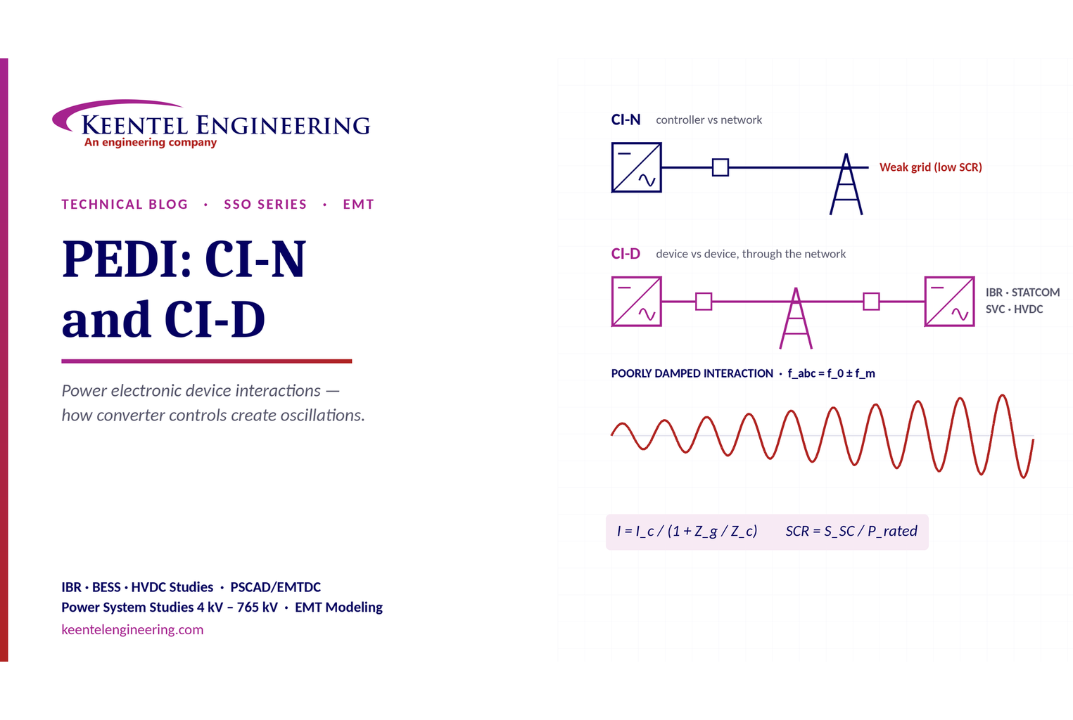
Learn power electronic device interactions (PEDI), including CI-N and CI-D, weak-grid stability, SCR, EMT studies, impedance analysis and mitigation for IBRs.
By SANDIP R PATEL
•
October 3, 2026
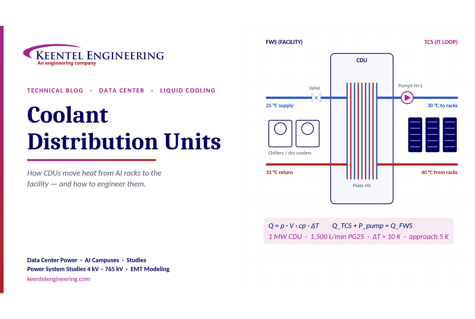
Learn how data center coolant distribution units (CDUs) work, including FWS and TCS loops, heat transfer, sizing, redundancy and liquid cooling for AI data centers.
By SANDIP R PATEL
•
October 3, 2026
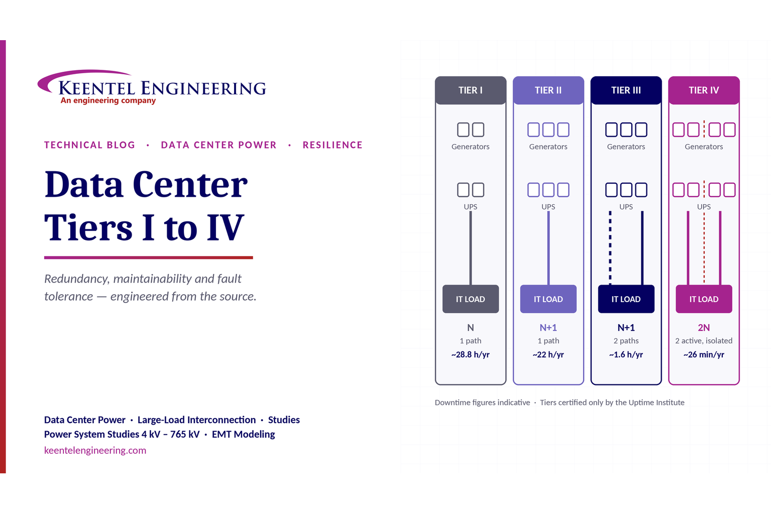
Compare Data Center Tiers I–IV, including redundancy, uptime, Tier III concurrent maintainability, Tier IV fault tolerance, UPS, generators and power design.

By SANDIP R PATEL
•
October 3, 2026
Learn how BESS supports grid stability through fast frequency response, voltage support, oscillation damping, black start, grid-forming controls and EMT studies.





