
A Coordinated Electric System Interconnection Review—the utility’s deep-dive on technical and cost impacts of your project.
Challenge: Frequent false tripping using conventional electromechanical relays
Solution: SEL-487E integration with multi-terminal differential protection and dynamic inrush restraint
Result: 90% reduction in false trips, saving over $250,000 in downtime
Bonneville Power Administration (BPA)'s Interconnection Model Requirements A Practical Guide for Developers and Engineers
jun 5, 2026 | Blog
Why This Matters
If you are developing a generation or load project that needs to connect to the Bonneville Power Administration (BPA) transmission grid, the models you submit are not paperwork — they are the technical evidence that your facility will behave the way you say it will. This guildeline spells out exactly what separates an acceptable model from an unacceptable one during the interconnection study process.
The blog "Technical Requirements for Interconnection to the BPA Transmission Grid." It is publicly released and written to align with FAC-001 interconnection-requirements documentation, so it functions as both a compliance reference and a practical checklist. For project developers, EPCs, OEMs, and consulting engineers, getting these models right the first time is the single most effective way to avoid study delays, rework cycles, and schedule slip.
This guide walks through the four model classes the standard covers, the facility data that underpins all of them, and the practical pitfalls Keentel Engineering sees most often.
The Big Picture: Four Model Families
Interconnection studies at BPA lean on four distinct but complementary model types, each answering a different engineering question:
- Positive-Sequence Power Flow — Can the system carry the steady-state injection/withdrawal and hold voltages within limits?
- Positive-Sequence Transient (PST / dynamic) models — How does the plant respond to system disturbances over seconds (angular stability, voltage recovery, frequency response)?
- Full-Sequence Fault Study models — What does the facility contribute to short-circuit duty, and does it preserve protection coordination?
- Electromagnetic Transient (EMT) models — How do fast power-electronic controls and protections behave in the microsecond-to-millisecond range, especially for inverter-based resources (IBRs)?
A modern solar, wind, storage, or hybrid project will typically need all four. Conventional synchronous machines may have lighter EMT obligations, but IBR-dominated plants are where the standard is most demanding — and where most rejections happen.
The requirements are explicitly written to track industry best practice, including IEEE Std 2800-2022 and the relevant NERC Reliability Guidelines for bulk-power-system transient modeling.
Foundation First: Facility Data
Before any model is judged, BPA expects a complete data package describing the physical plant. The standard is refreshingly pragmatic here — requirements can be satisfied with datasheets, nameplate photos, and marked-up notes about site-specific settings. The core data set includes:
- Project identity — facility name, commercial operation date (or estimate), EIA plant code if known, the Point of Interconnection (POI) bus name and nominal voltage, and the POI bus name/number in the WECC model.
- Electrical one-line diagram — covering switched capacitors/reactors, dynamic reactive devices, equipment ratings and connections, the collector system, transformer and generator configuration and grounding, bus and breaker/disconnect arrangements, loads, and the facility tie line.
- Energy source or load type — with MW, MVA, and kV nameplate values (e.g., solar, wind, hydro, gas, storage, etc.).
- Operating temperatures — maximum and minimum ambient.
- Station service — auxiliary load (kW and kVAR), connection description, and which distribution utility serves the plant when all generation is offline.
- Plant-level controls — voltage control (set-point location/value, droop, line-drop or reactive-current compensation, reactive capability in equation form), frequency control (governor droop, dead-band, IBR fast-frequency-response status), and any power system stabilizer.
- Inverter units — count, type, model, manufacturer, nameplate ratings, de-rate curves vs. temperature and elevation, and the DC energy source.
- Inverter loading ratio (ILR) — for PV, the DC panel capability to AC inverter capability ratio.
- Turbine generators — count, type, vendor, model, nameplate, governor manufacturer.
- Energy storage specifics — AC- vs. DC-coupling for hybrids, charge plan from the grid, energy capacity, max charge/discharge rate, and state-of-charge limits.
- Transformers (all of them) — GSU, collector main, unit, and load step-down units, with nameplate, winding configuration and ratio, X/R, zero-sequence data, fixed-tap detail, cooling class (ONAN/ONAF/OFAF) and ratings, impedance, and full OLTC settings.
- Other behind-the-POI equipment — switched shunts and dynamic reactive devices with ratings, counts, and locations on the one-line.
The recurring theme: the model must completely and accurately represent the as-planned (and ultimately as-built) facility. Equivalencing is allowed, but it must be documented and defensible.
1. Positive-Sequence Power Flow Models
The power flow model establishes steady-state behavior. BPA requires:
- A complete and accurate representation of the generator, step-up transformer, and behind-the-POI equipment (discrete shunts, STATCOMs and other dynamic reactive devices, tie-lines). Plant equivalents are acceptable when built per WECC modeling guidelines.
- A reactive capability curve for each explicitly modeled turbine generator and each equivalent unit, capturing the over-excitation limiter (OEL), under-excitation limiter (UEL), and rated power.
- For load interconnections, the completed Line and Load Interconnection Request form and a 20-year load forecast (projected, summer, and winter peak MW plus anticipated power factor) submitted as a CSV.
Accepted formats: PowerWorld (*.aux) or PSLF (*.epc).
A signed attestation of positive-sequence model accuracy (LGIP Attachment A to Appendix 1) accompanies the submission. The attestation is not a rubber stamp — it places accountability for accuracy on the Interconnection Customer.
2. Positive-Sequence Transient (PST) Models
Dynamic models must be WECC-approved and verified by the Interconnection Customer as accurately structured and parameterized. The required parameter set spans the generator, governor, excitation system, PSS, generator/converter model, electrical controls, plant-level control, and — for wind — the drivetrain, aerodynamic, pitch-controller, and torque-controller models. Relay parameters for overcurrent, under-frequency, and high/low frequency and voltage ride-through are also required.
For IBRs (including IBR storage), IEEE 2800-2022 Clause 10 (Modeling data) and Annex G apply.Critical pitfall: REPC_B plant-level models are not accepted.
This stems from limitations described in the WECC MVS guideline "Clarification on Proper Use of REPC Models." Submitting a REPC_B-based dynamic model is a guaranteed rejection — use an accepted plant controller representation.
For load interconnections, the dynamic package also needs relay settings, normal and event ramp rates, post-event recovery ramp rates, and the WECC Composite Load Model type and region.
Accepted format: PSLF (*.dyd). BPA may also provide a Model Acceptance Tool to streamline review; an optional tool report and input files can be submitted alongside the model.
3. Full-Sequence Fault Study Models
Short-circuit models confirm that the facility's fault contribution is correctly represented and that protection coordination at adjacent substations is preserved. Requirements include:
- An ASPEN OneLiner model, version 15 or later, with an aggregated equivalent generator/storage model expressing total MW and MVA output at each collector transformer secondary, referenced to both the system voltage and the POI.
- Type IV wind, solar, and storage modeled as a Voltage-Controlled Current Source (VCCS) or Converter-Interface Resource (CIR) generator — the older Current-Limited model is no longer valid for Type IV resources.
- Type III wind modeled with the Type III Wind Plant generator model.
- The collector transformer winding configuration with positive- and zero-sequence impedances for every configuration, plus any neutral grounding device needed to keep adjacent fault-detection relays sensitive on line-connected projects.
- Base-case simulations demonstrating accurate steady-state fault duty at the collection site.
The submission also expects a one-line to the POI, a summary of protective strategies and control philosophy at the POI, a summary of fault ride-through / reactive capability / voltage regulation behavior, the inverter's allowable short-circuit current range over the first 20 cycles for an adjacent line fault (used for slope calculations and normally provided by the inverter OEM), and the length plus positive/zero-sequence data of any customer-owned lines to the POI.
After commercial operation, the customer must supply "as-built" ASPEN OneLiner models validated to represent actual disturbance ride-through and short-circuit characteristics.
4. Electromagnetic Transient (EMT) Models — The Heavy Lift
For inverter-based resources, the EMT model is where most engineering scrutiny lands. BPA's requirements are tailored from NERC's March 2023 Reliability Guideline on EMT modeling for BPS-connected IBRs. Practically, the model must be high-fidelity, portable, and well-documented.
Software and structural requirements:
- PSCAD version 5.0.2 or later, compiled with the Intel Fortran compiler (compatible with Intel Fortran v15+ and Visual Studio 2015+).
- Both 32-bit and 64-bit libraries (Intel's 32-bit compiler is being phased out).
- Support for PSCAD snapshot and multiple-run features, and replication via copy / copy-transfer.
- Avoid simulation sets — they are hard to fold into large cases.
- Accurate operation at a timestep between 5 µs and 20 µs, without requiring a specific timestep.
Usability: control functions and parameters accessible; maximum accurate timestep stated; product variant easily identifiable; dispatchable via power and voltage set-point commands; comprehensive documentation (dependencies and limitations); a complete package (DLLs and libraries) that runs a quick verification test; easy scaling to larger/smaller plant capacity; and the ability to run multiple model instances in one simulation.
Efficiency: self-initialization to a dispatched level, reaching steady state in under ~5 seconds of wall-clock time, with no unreasonable computational burden.
Accuracy (the core of the standard):
- Documented collector-system and inverter-GSU equivalencing with visible ratings.
- Explicit, end-user-visible modeling of main transformers, substation components, and gen-tie lines; transformer nameplate matching test reports and site winding configurations; saturation characteristics included where known.
- Detailed fast control loops of the power electronics implemented as in the field.
- Realistic DC-side representation — an ideal DC voltage source is not acceptable if it prevents protection operation from being modeled.
- All pertinent control features and operating modes (inverter and plant level), with settings "certified" by the OEMs as field-appropriate.
- All relevant protection functions included (actual firmware code recommended), spanning inverter-level software/hardware protections and plant-level current/voltage/frequency tripping elements with vendor-specific detail.
- Each field device traceable to a specific inverter make, model, and software version, with OEM certification that the EMT model matches installed equipment.
- Communication and sampling delays modeled across inverters, plant controllers, automation controllers, metering, and protective relaying.
Black-box requirement: Controls must be black-boxed with no PSCAD master-library control blocks visible in the control circuits. If the model is not built on "real code," a separate validation report comparing the model against hardware tests (or hardware-in-the-loop) is required.
Documentation deliverables round out the package: facility type, full OEM list with
contacts, inverter/firmware/plant-controller inventory, plant identity data, spec sheets and manuals, protection settings, controls descriptions, settings-to-model mappings, one-lines, a user manual for BES reliability studies, descriptions of control modes (ideally with block diagrams of active/reactive control loops and grid-support functions), model limitations including maximum solution timestep, software requirements with versions, and setup/use instructions.
Beyond the Interconnection Study
The standard is careful to note that it covers modeling during interconnection. Once a project is in service,
NERC MOD standards — including MOD-032 and MOD-026/-027 — govern ongoing model validation and reporting, which BPA administers as a Planning Coordinator. A crucial, easily-missed obligation: a new model must be submitted every time a change to the facility alters its equipment response characteristic. Model maintenance is a lifecycle commitment, not a one-time gate.
How Keentel Engineering Helps
Building models that pass BPA review on the first pass takes more than running a study tool — it takes disciplined data management, OEM coordination, and fluency across PowerWorld, PSLF, ASPEN OneLiner, and PSCAD. Keentel Engineering supports developers and asset owners with:
- Full model package development across power flow, PST, fault, and EMT.
- EMT model validation and black-box compliance, including real-code confirmation and hardware-test validation reports.
- REPC model remediation for plants caught by the REPC_B prohibition.
- OEM liaison to obtain certifications, firmware-accurate controls, and short-circuit current ranges.
- Attestation and submission support aligned to the LGIP and FAC-001 documentation.
- Lifecycle model maintenance for MOD-032 / MOD-026/-027 obligations.
If you have a project entering BPA's queue — or a model that came back with comments — reach out to our interconnection team. Getting the models right is the fastest path through the study process.
This article summarizes BPA STD-N-000001-05 (Revision 00, dated 1/26/2026) for educational purposes. Always work from the current published standard and consult your BPA Customer Service Engineer for project-specific guidance.
Technical FAQ: BPA Interconnection Model Requirements
1. What is STD-N-000001-05 and how does it relate to STD-N-000001?
STD-N-000001-05 is a supporting document to the parent standard STD-N-000001, "Technical Requirements for Interconnection to the BPA Transmission Grid." The parent sets the technical requirements; the "-05" supporting document details the specific power flow, positive-sequence transient (PST), and EMT model requirements a generation or load facility must meet to receive interconnection study service. It is publicly released and written to align with FAC-001 documentation.
2. Which model types must I submit for an inverter-based resource?
A typical IBR project (solar, wind, storage, or hybrid) needs four model families: positive-sequence power flow, positive-sequence transient (dynamic), full-sequence fault study, and EMT. Each answers a different question — steady-state adequacy, electromechanical stability, short-circuit/protection behavior, and fast power-electronic dynamics, respectively.
3. What file formats does BPA accept for each model?
Power flow models are accepted in PowerWorld (*.aux) or PSLF (*.epc). Positive-sequence transient models are accepted in PSLF (*.dyd). Fault study models use ASPEN OneLiner version 15 or later. EMT models use PSCAD version 5.0.2 or later. Load forecast data for load interconnections is submitted as a CSV.
4. Why is the REPC_B plant-level model rejected, and what should I use instead?
REPC_B is not accepted because of limitations described in the "Relative Limits" section of the WECC MVS guideline "Clarification on Proper Use of REPC Models." Use a WECC-approved plant-level controller model that does not rely on REPC_B. If your dynamic package was originally built around REPC_B, plan on remediation before submission.
5. What is the attestation, and where does it come from?
For each model family (power flow, PST, fault, EMT), the Large Generator Interconnection Procedures (LGIP) Attachment A to Appendix 1 includes an attestation of model accuracy. The Interconnection Customer completes and submits it, formally taking responsibility that the model accurately represents the planned or installed equipment to the standard.
6. What timestep does the EMT model need to support?
The EMT model must simulate accurately for any timestep between 5 µs and 20 µs and must not require one specific timestep. It should also state the maximum solution timestep that preserves accuracy in its documentation.
7. Why must I provide both 32-bit and 64-bit PSCAD libraries?
BPA requires both because Intel will eventually discontinue its 32-bit Fortran compiler. Supplying both versions keeps the model usable across study environments during the transition. The model must compile with the Intel Fortran compiler and run under Intel Fortran v15+ and Visual Studio 2015+.
8. What does the "black-box" requirement mean for EMT controls?
Plant and inverter controls must be black-boxed so that no PSCAD master-library control blocks are visible inside the control circuits — the goal is to protect IP while preserving fidelity. If the model is not built on the manufacturer's "real code," you must provide a separate validation report comparing the model against hardware tests (or a hardware-in-the-loop platform).
9. Can I represent the DC side of an inverter as an ideal voltage source?
Not if doing so prevents protection operation from being modeled. The DC side and any current, power, or energy limitations must be represented well enough that relevant protection functions can operate in simulation. For storage, this includes charge/discharge limits and state-of-charge behavior.
10. How are different inverter technologies modeled in the fault study?
Type IV wind, solar, and storage must be modeled as a Voltage-Controlled Current Source (VCCS) or a Converter-Interface Resource (CIR) generator — the older Current-Limited model is no longer valid for Type IV resources. Type III wind uses the dedicated Type III Wind Plant generator model. Models are aggregated equivalents referenced at the collector transformer secondary and the POI.
11. What transformer data is required, and why so much detail?
Every transformer — GSU, collector main, unit, and load step-down — needs nameplate data, winding configuration and ratio, X/R, zero-sequence information, manufacturer test report data, fixed-tap detail, cooling class (ONAN/ONAF/OFAF) and ratings, impedance, and full OLTC settings (tap counts, size, regulating voltage, and timing). This detail drives accurate voltage regulation, fault duty, and zero-sequence grounding behavior, all of which affect adjacent protection.
12. What is the inverter short-circuit current range over 20 cycles used for?
It defines the allowable inverter short-circuit current behavior during the first 20 cycles of a transmission-line fault immediately adjacent to the project. It is normally provided by the inverter manufacturer and is used for slope calculations in the protection and fault analysis — essential for confirming relay coordination at neighboring substations.
13. What additional data do load interconnections require?
Beyond the standard package, load interconnections need a completed Line and Load Interconnection Request, a 20-year load forecast (projected, summer, and winter peak MW plus anticipated power factor) as a CSV, relay ride-through settings, normal and event ramp rates, post-event recovery ramp rates, and the appropriate WECC Composite Load Model type and region.
14. What industry standards and guidelines does STD-N-000001-05 align with?
It is written to align with IEEE Std 2800-2022 (notably Clause 10 modeling data and Annex G for IBRs) and NERC Reliability Guidelines for BPS transient modeling. The EMT section is tailored from NERC's March 2023 "Reliability Guideline: Electromagnetic Transient Modeling for BPS-Connected Inverter-Based Resources." It also references WECC modeling guidelines and ERCOT's PSCAD submittal guidelines as supporting practice.
15. What are my modeling obligations after the project is energized?
Interconnection modeling is only the start. After commercial operation you must provide validated "as-built" ASPEN OneLiner models, and you remain subject to NERC MOD standards — MOD-032 and MOD-026/-027 — which BPA administers as a Planning Coordinator. Critically, you must submit a new model every time a facility change alters the equipment's response characteristic. Model maintenance is a lifecycle obligation.
Have a project in the BPA queue or a model that needs validation? Contact Keentel Engineering's interconnection modeling team.

About the Author:
Sonny Patel P.E. EC
IEEE Senior Member
In 1995, Sandip (Sonny) R. Patel earned his Electrical Engineering degree from the University of Illinois, specializing in Electrical Engineering . But degrees don’t build legacies—action does. For three decades, he’s been shaping the future of engineering, not just as a licensed Professional Engineer across multiple states (Florida, California, New York, West Virginia, and Minnesota), but as a doer. A builder. A leader. Not just an engineer. A Licensed Electrical Contractor in Florida with an Unlimited EC license. Not just an executive. The founder and CEO of KEENTEL LLC—where expertise meets execution. Three decades. Multiple states. Endless impact.
Services

Let's Discuss Your Project
Let's book a call to discuss your electrical engineering project that we can help you with.
About the Author:
Sonny Patel P.E. EC
IEEE Senior Member
In 1995, Sandip (Sonny) R. Patel earned his Electrical Engineering degree from the University of Illinois, specializing in Electrical Engineering . But degrees don’t build legacies—action does. For three decades, he’s been shaping the future of engineering, not just as a licensed Professional Engineer across multiple states (Florida, California, New York, West Virginia, and Minnesota), but as a doer. A builder. A leader. Not just an engineer. A Licensed Electrical Contractor in Florida with an Unlimited EC license. Not just an executive. The founder and CEO of KEENTEL LLC—where expertise meets execution. Three decades. Multiple states. Endless impact.
Leave a Comment
Thank you for contacting us.
We will get back to you as soon as possible.
We will get back to you as soon as possible.
Oops, there was an error sending your message.
Please try again later.
Please try again later.
Related Posts
By SANDIP R PATEL
•
July 21, 2026
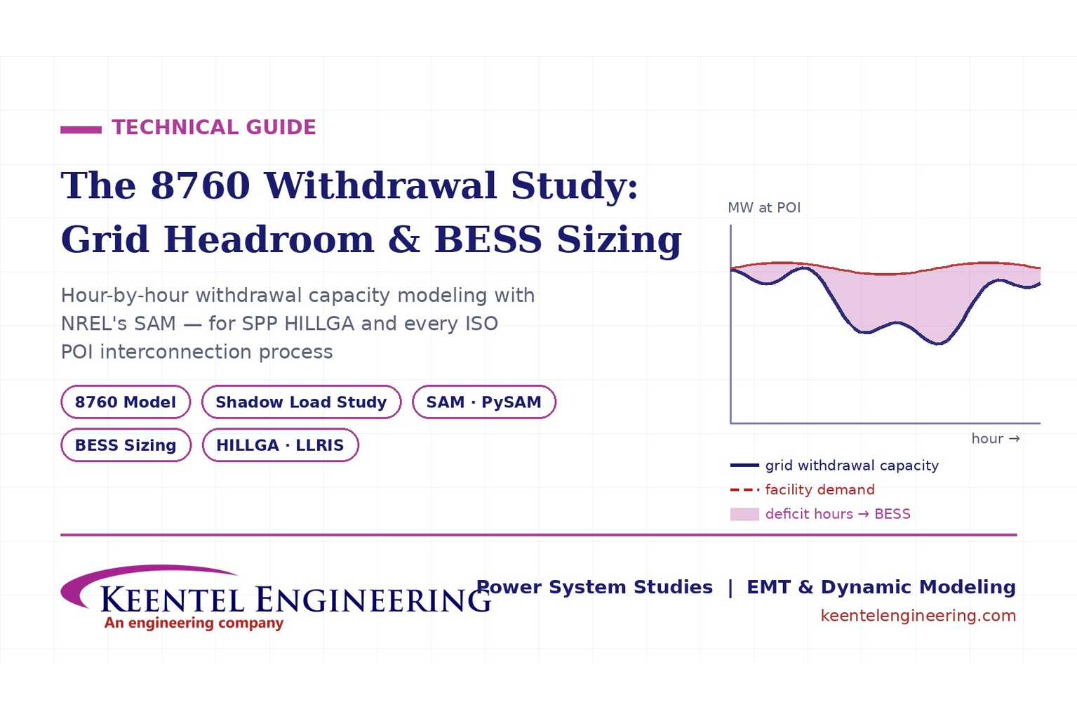
Learn how an 8760 withdrawal study models hourly grid headroom and uses SAM-based BESS sizing for large-load interconnection projects.
By SANDIP R PATEL
•
July 21, 2026
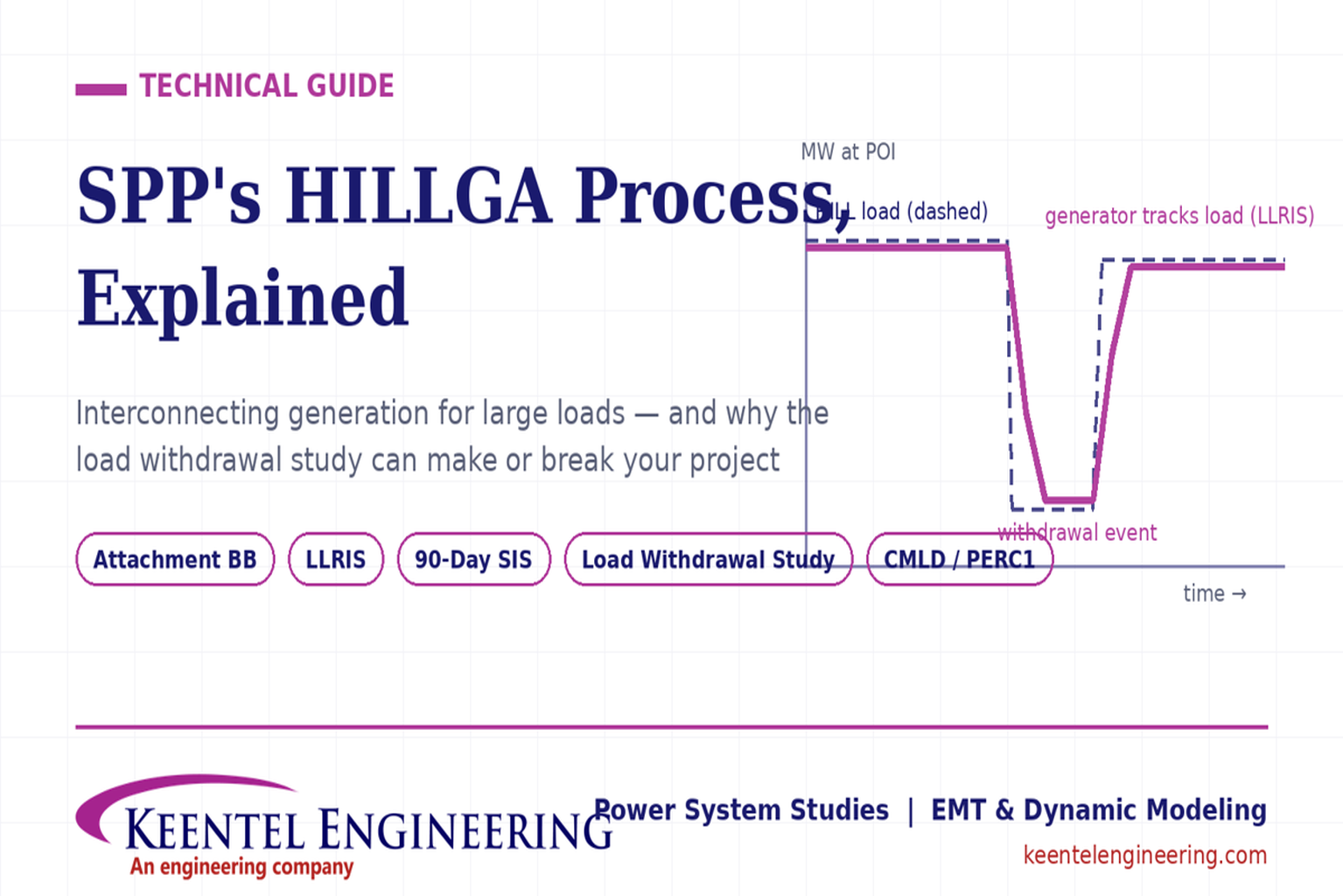
Learn how the SPP HILLGA process supports data center generation interconnection and why an 8760 withdrawal study can determine project success.
By SANDIP R PATEL
•
July 19, 2026
Learn electrical protection and relay coordination for hyperscale data centers with IEEE standards, short-circuit studies, arc-flash analysis, and MV protection.
By SANDIP R PATEL
•
July 18, 2026
Explore Battery Energy Storage System components, including cells, PCS, BMS, EMS, cooling, fire protection, sizing, safety, and grid codes.

By SANDIP R PATEL
•
July 18, 2026
Explore how grid-forming inverters support BESS, synthetic inertia, grid-code compliance, plant sizing, testing, and project revenue.
By SANDIP R PATEL
•
July 18, 2026
Learn how SEL RTAC protection monitoring supports NERC PRC-005 compliance, predictive maintenance alarms, automated reporting, and relay verification.
By SANDIP R PATEL
•
July 17, 2026
Explore utility-scale BESS design from the 10% package to IFC, NFPA 855 compliance, PSS®E/PSCAD models, and ERCOT interconnection.
By SANDIP R PATEL
•
July 17, 2026
Substation design guide, electrical substation design, substation equipment sizing, IEEE 80 grounding design, IEEE 998 lightning shielding, bus configuration design
By SANDIP R PATEL
•
July 15, 2026
Learn how medium-voltage switchgear improves data center reliability with expert guidance on MV architecture, protection, redundancy, commissioning, and maintenance.


