
A Coordinated Electric System Interconnection Review—the utility’s deep-dive on technical and cost impacts of your project.
Challenge: Frequent false tripping using conventional electromechanical relays
Solution: SEL-487E integration with multi-terminal differential protection and dynamic inrush restraint
Result: 90% reduction in false trips, saving over $250,000 in downtime
The three operating regions you have to design to
| Device | Output vs voltage | Response | Best suited to | Main limitations |
|---|---|---|---|---|
| Mechanically switched capacitor or reactor | Proportional to voltage squared | Seconds; discrete steps; limited switching operations per day | Steady-state reactive supply, voltage profile, loss reduction | No dynamic capability; step voltage change on switching; capability collapses when most needed |
| Static var compensator | Capacitive branches proportional to voltage squared | A few cycles; continuously controllable | Continuous control where cost matters and deep voltage support is not the driver | Square-law capability loss; harmonic filters are part of the plant and interact with the network |
| STATCOM | Approximately proportional to voltage — constant current capability | One to two cycles closed loop; converter response faster still | Voltage stability margin, weak interconnections, fast disturbance recovery, flicker and unbalance compensation | Higher capital cost; converter losses; adds a converter and its control dynamics to the network |
| Synchronous condenser | Governed by machine capability and excitation | Excitation response in the hundreds of milliseconds; inherent inertial response instantaneous | System strength and inertia, short-circuit contribution, black start support | Rotating plant with maintenance and losses; slower controlled response than a converter |
| STATCOM with energy storage | Reactive as a STATCOM, plus real power within the storage rating | As STATCOM for reactive; real power limited by storage | Where a real power deficiency is part of the problem | Cost and complexity of the storage; different failure and maintenance profile |
| Stage | Keentel scope | Outcome |
|---|---|---|
| Screening | Series-compensation proximity, radial contingency review, UIF and short-circuit ratio screening, frequency scans | Early identification of which SSO types apply |
| Detailed studies | PSCAD/EMTDC EMT studies with vendor real-code models, impedance-based and frequency-scan analysis | Clear evidence of stability margins or risk |
| Model quality | EMT model review, benchmarking against positive-sequence models, model acceptance support | Models that system operators accept |
| Mitigation | Control retuning recommendations with vendors, SSDC and bypass logic requirements, protection and monitoring specifications | Practical, coordinated solutions |
| Interconnection support | SSR and SSO study reports for ISO and utility requirements, response to reviewer comments | Fewer delays in the interconnection process |
Data Center Coolant Distribution Units: An Engineering Guide to Liquid-Cooling Heat Transfer
October 03, 2026 | Blog
Part A — Coolant Distribution Units at a Glance
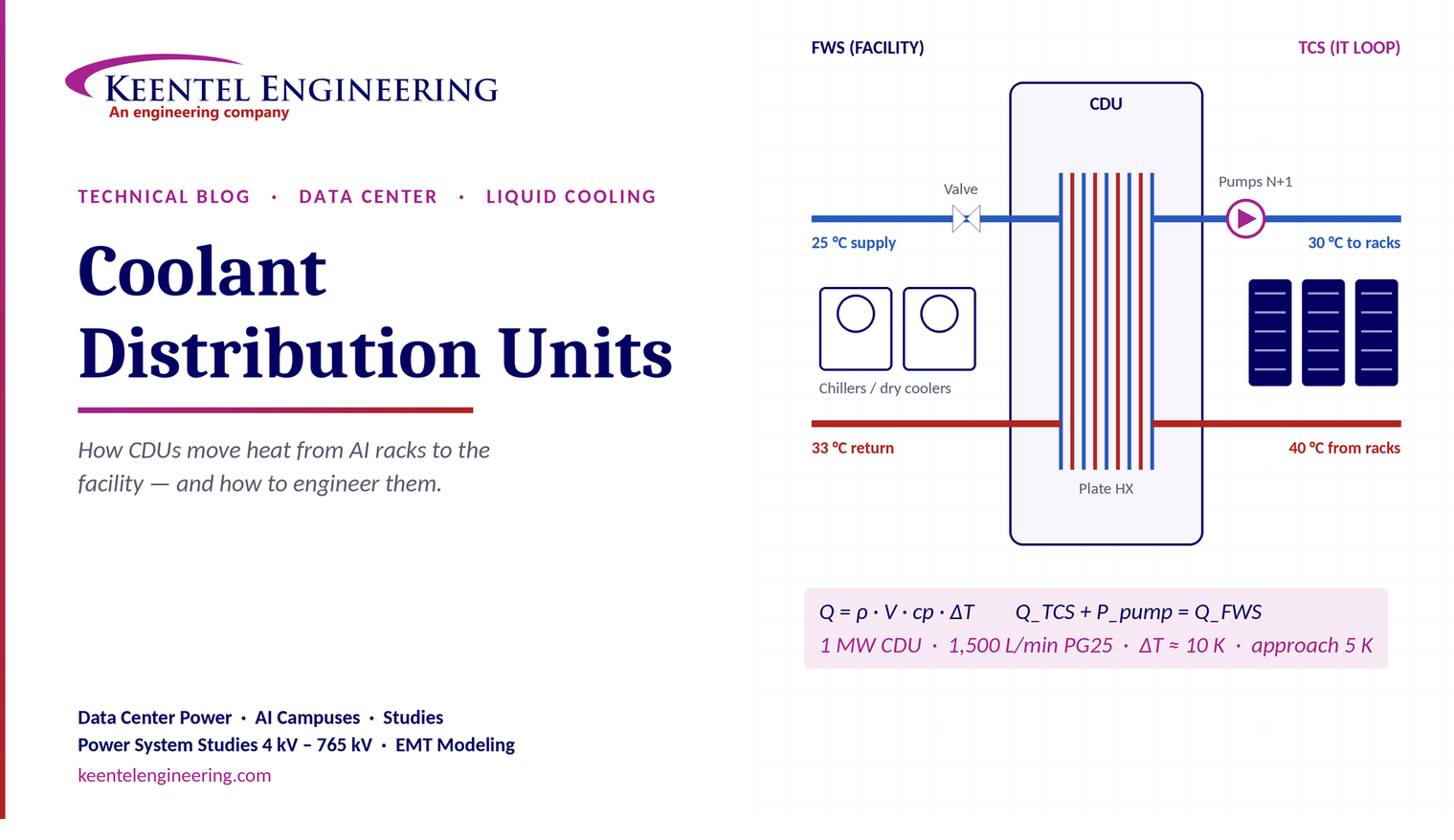
A coolant distribution unit (CDU) is the heart of a liquid-cooled data center. It sits between the facility water system and the IT cooling loop, transfers heat between them through a heat exchanger, and controls the flow, pressure and temperature of the coolant delivered to the racks. The two fluids never mix.
How heat moves through a CDU, in four steps
- Cool coolant enters from the facility. The facility water system (chillers, cooling towers or dry coolers) delivers cool water to the primary side of the CDU.
- The CDU manages the flow. A control valve modulates facility water through the plate heat exchanger, while redundant pumps circulate the secondary coolant through filters to the racks at a controlled pressure.
- Coolant absorbs the IT heat. Coolant flows through cold plates on processors and accelerators, picks up heat and returns warmer to the CDU.
- Heat is rejected to the facility. The heat exchanger transfers that heat to the facility water, which returns to the plant for rejection.
The two loops
| Item | Primary circuit — facility water system (FWS) | Secondary circuit — technology cooling system (TCS) |
|---|---|---|
| Serves | Chillers, cooling towers or dry coolers | IT racks: cold plates, manifolds, rear-door heat exchangers |
| Typical fluid | Treated facility water | Propylene glycol 25% (PG25) or treated water |
| Controlled by | Facility plant, and the CDU's modulating valve | CDU pumps, valves and controls |
| Key measurements | Supply and return temperature, flow, valve position | Supply and return temperature, flow, differential pressure, system pressure |
| Cleanliness | Facility water quality programme | Tight filtration, often 50 µm or finer, and fluid chemistry monitoring |
Main CDU components
| Component | Function |
|---|---|
| Plate heat exchanger | Transfers heat between the loops while keeping the fluids separate |
| Primary control valve | Modulates facility water flow to hold the secondary supply temperature |
| Main pumps (N+1 or 2N) | Circulate the secondary coolant and set its flow and differential pressure |
| Filter or strainer | Removes particles that would block cold-plate micro-channels |
| Expansion tank and fill pump | Maintain secondary system pressure and make up fluid losses |
| Sensors and controls | Temperature, flow, pressure, leak and fluid-quality monitoring; BMS integration |
| Drain and fill points | Commissioning, maintenance and fluid replacement |
The CDU isolates the IT from the facility. That isolation lets each loop use the right fluid, pressure and cleanliness, and keeps a facility-side problem from reaching the servers directly.
Part B — Data Center Coolant Distribution Units: An Engineering Guide to Liquid-Cooling Heat Transfer
How CDUs work, how to size and check them with real heat balances, and what liquid cooling means for the electrical, mechanical and resilience design of AI and high-density data centers.
Why liquid cooling, and why now
Air cooling works well up to roughly 15–30 kW per rack, depending on containment and airflow design. AI training and inference racks now draw tens to well over 100 kW each, with processors and accelerators that dissipate hundreds of watts to over a kilowatt per chip. Air cannot carry that heat away efficiently: water has about 3,500 times the volumetric heat capacity of air, so a small pipe does the work of a very large duct.
Direct-to-chip (cold-plate) liquid cooling has therefore become the default for high-density AI hardware. The CDU is the device that makes it practical, by delivering clean, temperature-controlled coolant to the racks while connecting to the building's existing or new facility water plant.
The vocabulary: FWS, TCS and approach
ASHRAE TC 9.9 and the Open Compute Project (OCP) use a consistent set of terms:
- Facility water system (FWS): the primary loop from the cooling plant to the CDU.
- Technology cooling system (TCS): the secondary loop from the CDU to the IT equipment.
- Approach temperature difference (ATD): TCS supply temperature minus FWS supply temperature. OCP's liquid-to-liquid CDU test methodology rates capacity at an ATD of 5 °C.
ASHRAE classifies facility water by its maximum supply temperature. All classes have a lower limit of 2 °C:
| ASHRAE class | Maximum facility water supply | Typical heat rejection |
|---|---|---|
| W17 (formerly W1) | 17 °C | Chillers |
| W27 (formerly W2) | 27 °C | Chillers with economisers, cooling towers |
| W32 (formerly W3) | 32 °C | Cooling towers, dry coolers in many climates |
| W40 (new) | 40 °C | Dry coolers, chiller-free in most climates |
| W45 (formerly W4) | 45 °C | Dry coolers; heat reuse becomes practical |
| W+ (formerly W5) | Above 45 °C | Heat reuse, district heating |
Warmer facility water means fewer chiller hours, lower energy use and more free cooling. The limit is set by the IT equipment: the TCS supply temperature the server vendor allows, minus the CDU's approach.
Inside the CDU
The plate heat exchanger
Brazed or gasketed plate heat exchangers provide a large surface area in a compact volume. The two fluids flow counter-current through alternate channels, which allows a close approach temperature. Plate surface patterns create turbulence and improve heat transfer, at the cost of pressure drop. The exchanger is sized for the design heat load, the approach and the allowable pressure drop on both sides, with margin for fouling.
Primary control valve
A modulating valve on the facility side, typically controlled to hold the TCS supply temperature at its setpoint, adjusts how much facility water passes through the exchanger. At low IT load it throttles back; at full load it opens. Valve authority and characteristic matter: an oversized valve operating near closed gives poor control and temperature hunting.
Pumps and pressure control
The CDU's pumps circulate the TCS coolant through the manifolds and cold plates. They are usually variable-speed, controlled on differential pressure across the supply and return headers or on flow. Redundancy of at least N+1 is standard practice, so one pump can fail or be serviced without interrupting flow.
An expansion tank absorbs thermal expansion, and a fill pump maintains system static pressure and makes up small losses. Low pressure can indicate a leak; high pressure can indicate thermal expansion problems or a closed path.
Filtration and fluid quality
Cold plates use fine internal channels and micro-fins, often a few hundred micrometres wide, which can be blocked by debris. OCP's CDU test methodology references a primary filter of 200 µm or finer and a secondary filter of 50 µm or finer. OCP's PG25 guidance recommends fluid filtered at 50 µm or finer before delivery, with 25 µm preferred, and continuous sidestream filtration of a portion of the circulating flow.
Sensors, controls and leak detection
A modern CDU monitors supply and return temperatures on both loops, flow, differential and static pressure, pump status, valve position, filter differential pressure and fluid level. Many also monitor coolant conductivity or quality. Leak detection cable under manifolds and at rack connections, integrated with the building management system, is essential.
The heat balance: every CDU calculation starts here
Heat carried by a liquid stream is:
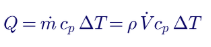
In steady state, the heat picked up by the TCS from the IT equipment, plus pump heat, must equal the heat rejected to the FWS:

A worked check: when the numbers do not balance
Consider a CDU reported with these operating values:
| Measurement | Value |
|---|---|
| FWS supply / return | 9.7 °C / 15.2 °C (ΔT 5.5 K) |
| FWS flow | 70 L/min |
| TCS supply / return | 22.2 °C / 34.6 °C (ΔT 12.4 K) |
| TCS flow | 87 L/min |
| Primary valve position | 87% |
| TCS differential pressure | 1.02 bar |
| TCS system pressure | 0.58 bar |
TCS side (PG25, ρ ≈ 1.02 kg/L, c_p ≈ 3.93 kJ/kg·K): 87 ÷ 60 × 1.02 × 3.93 × 12.4 ≈ 72 kW.
FWS side (water, ρ ≈ 1.00 kg/L, c_p ≈ 4.18 kJ/kg·K): 70 ÷ 60 × 1.00 × 4.18 × 5.5 ≈ 27 kW.
The two sides differ by a factor of about 2.7, which is physically impossible in steady state. Either a measurement is wrong or the plant is not in steady state. To carry 72 kW, the facility side needs either about 189 L/min at a 5.5 K rise, or a rise of about 14.8 K at 70 L/min, which would put the facility return near 24.5 °C rather than 15.2 °C.
This check is one of the most valuable commissioning and troubleshooting tools for liquid cooling. A heat balance that does not close usually points to a faulty flow meter, a mislocated temperature sensor, a bypass flow, or air in the loop.
Two other things in these values deserve attention:
- Approach. TCS supply at 22.2 °C with FWS supply at 9.7 °C is a 12.5 K approach. A well-sized CDU typically achieves a few degrees. A large approach with the valve 87% open suggests an undersized or fouled heat exchanger, or reduced FWS flow.
- Condensation. Facility water at 9.7 °C is below the dew point of many data hall environments. Exposed FWS piping, valves and the CDU's primary side must be insulated with a vapour barrier, or the facility water temperature raised. ASHRAE guidance for data halls commonly uses a maximum dew point of 15 °C.
A consistent design example: a 1 MW in-row CDU
| Parameter | TCS (PG25) | FWS (water) |
|---|---|---|
| Heat load | 1,000 kW | 1,000 kW plus pump heat |
| Supply temperature | 30 °C | 25 °C (approach 5 K; ASHRAE W27) |
| Return temperature | ≈ 40 °C | ≈ 33 °C |
| Temperature rise | ≈ 10 K | 8 K |
| Flow | 1,500 L/min (1.5 L/min per kW) | ≈ 1,800 L/min |
Check the TCS flow: 1,500 ÷ 60 × 1.02 × 3.93 × 10 ≈ 1,002 kW. The 1.5 L/min per kW figure matches the flow basis OCP uses for CDU capacity rating, and gives a TCS temperature rise of about 10 K with PG25.
The pump power needed to circulate the TCS is:
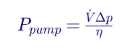
With 1,500 L/min (0.025 m³/s), a total differential pressure of 2.5 bar (250 kPa) and a combined pump and motor efficiency of 60%, the pump draws about 0.025 × 250 ÷ 0.6 ≈ 10.4 kW. That heat enters the TCS and must also be rejected through the CDU.
Coolant choice: water or PG25
| Property | Treated water | PG25 |
|---|---|---|
| Heat transfer | Best | Somewhat lower specific heat and higher viscosity; needs more flow or a larger ΔT |
| Freeze protection | None | Protection for shipping, storage and cold environments |
| Biological growth | Requires biocide treatment | Biostatic at the specified concentration |
| Corrosion | Requires an inhibitor programme | Supplied with an inhibitor package |
| Typical use | Facility water systems; some TCS loops | The common default for TCS loops in OCP guidance |
OCP's PG25 guidance specifies 24.5–27.5% propylene glycol by volume, compatible wetted materials (copper, low-zinc brass, 304L and 316L stainless steel, EPDM, FKM, PTFE and others), and periodic monitoring of glycol concentration, pH and contaminants. It also specifies high-purity flush water and filling the system with coolant soon after the final flush, preferably within 24 hours, to prevent biological growth.
CDU types and placement
| Type | Typical capacity | Location | Strengths and trade-offs |
|---|---|---|---|
| In-rack CDU | Tens to about 100+ kW | Inside the rack | Simple deployment rack by rack; consumes rack space; many small units to maintain |
| In-row CDU | Hundreds of kW to over 1 MW | In the row with the racks | Serves a row through manifolds; balances capacity and redundancy |
| Facility or centralised CDU | Several MW | Mechanical gallery outside the white space | Fewer, larger units; keeps maintenance outside the data hall; longer TCS piping |
| Liquid-to-air CDU (sidecar) | Tens to low hundreds of kW | Next to the rack | Rejects heat to room air; used where no facility water is available; limited capacity |
Resilience: designing CDUs to the facility Tier objective
Liquid cooling makes heat removal more critical, not less. Cold plates hold only seconds of thermal buffer. If TCS flow stops, processors throttle or shut down very quickly. Resilience design must therefore cover:
- Pump redundancy: N+1 pumps at minimum, with automatic changeover.
- CDU redundancy: N+1 CDUs on a common TCS header, or 2N CDUs serving A and B manifolds for fault-tolerant designs.
- Power to CDUs: dual-corded CDUs fed from A and B sources, with pumps and controls on UPS power so coolant keeps flowing through a utility failure and generator start. This is the liquid-cooling equivalent of continuous cooling.
- Facility water continuity: chilled water or condenser water must also continue, through thermal storage, UPS-backed pumps or a high enough FWS temperature that the TCS can coast on stored thermal mass for the transfer period.
- Concurrent maintainability: isolation valves so any CDU, pump, filter or manifold section can be serviced without stopping the others.
- Leak management: leak detection, drip trays, automatic isolation valves and procedures for fluid spills.
Electrical engineering considerations
CDUs and liquid-cooling plants are electrical loads with their own design requirements:
- Pump motors and VFDs. Large CDUs use variable-frequency drives on their pump motors. These introduce harmonic current that must be included in the facility's harmonic study and IEEE 519 evaluation.
- Critical mechanical load on UPS. Putting CDU pumps on UPS increases UPS and battery sizing. The mechanical UPS load must be included in redundancy and ride-through calculations.
- Feeder and protection design. Dual feeds, automatic transfer, selective coordination and arc-flash labelling apply to CDU power distribution just as they do to IT power.
- Generator transient response. CDU pumps restarting together after a transfer create motor inrush on the generators. Staged restarts and soft acceleration reduce the step load.
- Load dynamics. AI training loads can swing rapidly between high and low power. Cooling controls must track those swings without temperature overshoot, and electrical systems must handle both the IT and the cooling load changes.
Commissioning a liquid-cooled data hall
- Flush and clean the TCS piping and manifolds to the specified cleanliness, using high-purity flush water.
- Fill and vent with the specified coolant, verifying glycol concentration and chemistry.
- Pressure test for leaks at design and test pressures, including quick-disconnect fittings.
- Verify sensors and controls: flow meters, temperature sensors, pressure transmitters, leak detection and BMS points.
- Load test with heat load banks connected through the cold-plate interfaces or rack manifolds, across the operating range.
- Prove the heat balance on both loops at several load steps, and the approach temperature against the design.
- Test failure scenarios: pump failure, CDU failure, power transfer to generator, valve failure and loss of facility water, confirming temperatures stay within the IT vendor's limits.
How Keentel Engineering helps
Keentel Engineering supports data center owners, developers and EPCs with the electrical engineering that liquid-cooled facilities depend on, and coordinates with the mechanical engineer of record and cooling vendors on the integrated design.
| Element | Tier I | Tier II | Tier III | Tier IV |
|---|---|---|---|---|
| Utility service | Single | Single | Single or dual (not counted towards the Tier) | Single or dual (not counted towards the Tier) |
| Engine generators | N | N+1 | N+1, continuous-rated, concurrently maintainable paralleling | N+1 or 2N, fault-tolerant paralleling and controls |
| Medium-voltage and low-voltage switchgear | Single bus | Single bus | Main-tie-main or dual buses; isolation on both sides of every component | Physically separated A and B switchgear |
| UPS | N | N+1 | N+1 with dual output paths, or 2N | 2N, 2N+1 or distributed redundant, compartmentalised |
| Distribution to IT | Single path | Single path | A and B paths; rack ATS for single-corded loads | A and B paths, physically separated |
| Fuel | 12 h minimum | 12 h minimum, redundant pumps | 12 h minimum, concurrently maintainable supply | 12 h minimum, fault-tolerant supply |
| Cooling | N | N+1 | N+1 with maintainable piping and valves | Fault tolerant, compartmentalised, continuous cooling |
Planning a liquid-cooled AI data hall or a retrofit of an existing facility? Talk to Keentel Engineering at (813) 389-7871, contact@keentelengineering.com, or book a 15-minute scoping call at calendly.com/keentel-engineering/15min.
Part C — Case Studies
The following are illustrative scenarios based on conditions typical of liquid-cooled data centers. They show how Keentel Engineering approaches the power and resilience side of liquid cooling; site details are generalised and figures are rounded.
Case Study 1 — Retrofitting an air-cooled hall for AI racks
Situation. An enterprise data center with a chilled-water plant and an air-cooled hall plans to install a row of AI racks at about 120 kW each, served by in-row CDUs.
Analysis. The study confirms that the existing chilled-water plant has thermal capacity, but at its 7–10 °C supply temperature the facility water is well below the hall's dew point, creating condensation risk at the CDUs. The electrical review finds that the existing mechanical distribution boards are single-fed and not on UPS, so a utility failure would stop CDU pumps for the 30–60 seconds before generators carry the load.
Engineered solution. A dedicated warmer-water secondary loop from the chilled-water plant through a mixing station, raising facility water to the CDUs above the dew point, coordinated with the mechanical engineer. On the electrical side, new dual-fed CDU distribution from A and B sources, with CDU pumps and controls on a mechanical UPS sized for the transfer period, and staged pump restarts on generator.
Outcome. The AI row operates without condensation risk, and cooling flow continues uninterrupted through a simulated utility failure during integrated testing.
Case Study 2 — Heat balance reveals a commissioning fault
Situation. During commissioning of a liquid-cooled hall, CDU trend data shows the TCS removing far more heat than the facility water appears to carry, with the facility control valve near fully open and a large approach temperature.
Analysis. A heat balance at several load steps shows the facility side consistently reporting about one-third of the TCS heat. Investigation finds a facility-side flow meter configured with the wrong pipe size and a partially closed balancing valve that had not been reset after flushing.
Engineered solution. Correct the flow meter configuration, reset the balancing valve, and re-run the load steps. Add heat-balance checks to the commissioning scripts and to the BMS as a continuous diagnostic alarm.
Outcome. Heat balances close within a few percent, the approach falls to its design value, and the valve operates in its controllable range, leaving cooling capacity for future rack additions.
Case Study 3 — Power design for a 40 MW liquid-cooled AI campus building
Situation. A developer designs a 40 MW IT building for AI training with direct-to-chip cooling, served by a warm-water facility system with dry coolers and trim chillers. The owner wants fault-tolerant cooling and minimal UPS cost.
Analysis. Keentel models the electrical load of CDUs, facility pumps and heat rejection plant, along with the IT load and its rapid swings during training. The analysis compares putting all mechanical load on UPS against putting only CDU and TCS pumps on UPS while relying on thermal inertia of the facility loop during generator start.
Engineered solution. CDU pumps and controls on 2N UPS with the IT load, facility pumps on a separate mechanical UPS sized for the generator transfer, and dry-cooler fans on generator-backed distribution. Harmonic studies include all VFD-driven pumps and fans, and generator sizing includes staged restart of the mechanical plant.
Outcome. The design maintains coolant flow through power events, meets the owner's fault-tolerance objective for cooling, and avoids oversizing UPS for loads that can tolerate a short interruption.
Part D — Technical FAQ: Coolant Distribution Units
A CDU is a liquid-cooling device that transfers heat from the IT cooling loop (TCS) to the facility water system (FWS) through a heat exchanger. It also pumps, filters and controls the coolant delivered to the racks, keeping the two fluids separate.
The facility water system (FWS) is the primary loop from the cooling plant to the CDU. The technology cooling system (TCS) is the secondary loop from the CDU to the IT equipment's cold plates or other liquid-cooled components.
The TCS needs very clean, chemically controlled coolant at a stable temperature and pressure, because cold plates have fine channels and server components are sensitive. Facility water systems are larger and harder to keep that clean. Separation also limits how much fluid could leak inside the IT space.
It is the difference between TCS supply temperature and FWS supply temperature. A smaller approach means a more effective heat exchanger and allows warmer facility water. OCP's CDU test methodology rates capacity at an approach of 5 °C.
ASHRAE classifies facility water from W17 (up to 17 °C) through W27, W32, W40 and W45 to W+ (above 45 °C). Many liquid-cooled designs aim for W27 to W40, which allows extensive free cooling with dry coolers or cooling towers.
Q = flow × density × specific heat × temperature difference. For PG25, 87 L/min with a 12.4 K rise carries about 72 kW. The same heat, plus pump heat, must appear on the facility side.
Because it must close in steady state. A heat balance that does not close usually points to a faulty flow meter, a misplaced temperature sensor, a bypass, air in the loop or an unsteady operating condition. It is a simple and powerful commissioning and troubleshooting check.
A common basis is about 1.5 L/min per kW of IT load, which gives a temperature rise of about 10 K with PG25. Actual flows are set by the server vendor's cold-plate requirements and allowable supply and return temperatures.
PG25 provides freeze protection, is biostatic at its specified concentration, and comes with corrosion inhibitors for mixed-metal loops. OCP guidance specifies 24.5–27.5% propylene glycol by volume. The trade-off is slightly lower heat transfer than water.
Cold plates have fine channels that debris can block. OCP references a secondary filter of 50 µm or finer in CDU testing, and recommends fluid filtered at 50 µm or finer, preferably 25 µm, with continuous sidestream filtration in operation.
It modulates facility water flow through the heat exchanger to hold the TCS supply temperature at its setpoint. At high load it opens; at low load it throttles. A valve operating near fully open at moderate load suggests insufficient facility flow, a fouled exchanger or an incorrect setpoint.
Variable-speed pumps are usually controlled on differential pressure across the TCS supply and return headers, or on flow. This maintains the pressure that rack manifolds and cold plates need as racks are added or their valves modulate.
At least N+1 pumps within each CDU, and N+1 or 2N CDUs serving a common or dual header, depending on the facility's resilience objective. Power to CDUs should come from A and B sources, with automatic changeover.
Cold plates hold very little thermal buffer. If coolant flow stops during the seconds to a minute before generators pick up the load, processors can throttle or shut down. Keeping CDU pumps and controls on UPS maintains flow, the liquid-cooling equivalent of continuous cooling.
It depends on the design. If the TCS can rely on the stored thermal mass of the facility loop for the transfer period, facility pumps may tolerate a short interruption. Otherwise, facility pumps, thermal storage or both need uninterrupted power.
Any surface colder than the room's dew point. Facility water from conventional chillers at 7–10 °C can be below the data hall dew point. Warm-water designs largely avoid this, but cold facility piping must be insulated with a vapour barrier.
In-rack CDUs serve a single rack; in-row CDUs serve a row through manifolds; facility CDUs serve many rows from outside the white space; and liquid-to-air CDUs reject heat to room air where facility water is not available.
From the IT heat load, required TCS supply temperature, available FWS temperature, approach, allowable flows and pressure drops, and redundancy. Margin should cover future rack additions, fouling and the pump heat added to the loop.
Pump power is flow × differential pressure ÷ efficiency. A 1 MW CDU moving 1,500 L/min at 2.5 bar with 60% efficiency draws about 10 kW, about 1% of the IT load. That heat is added to the TCS and must also be rejected.
Yes. Variable-frequency drives on pump motors draw harmonic current. Large liquid-cooled facilities have many such drives, so they must be included in harmonic studies and IEEE 519 compliance at the point of common coupling.
AI training can swing power rapidly across a whole hall. Coolant temperature control must respond without overshoot, and pumps and valves must track the load. Simultaneous swings also affect the electrical system, so cooling and power controls should be studied together.
With leak detection at manifolds and rack connections, drip trays, dripless quick-disconnects, automatic isolation valves, pressure monitoring that detects slow losses, and procedures for response and cleanup. Negative-pressure TCS designs are another option in some systems.
OCP guidance calls for thorough flushing with high-purity water (pH 5–8, low chloride, sulfate and hardness, and conductivity below 25 µS/cm), then filling with coolant soon after the final flush, preferably within 24 hours, to prevent biological growth.
By flushing and filling, pressure testing, verifying all sensors and controls, load testing with heat load banks, proving heat balances and approach temperatures at several load steps, and testing failure scenarios such as pump, CDU and power failures.
Yes. Liquid carries heat far more effectively than air, reducing fan energy. Warmer facility water allows more free cooling and fewer chiller hours, and in some cases enables heat reuse. The overall benefit depends on the plant design and climate.
References and Further Reading
Links were current at publication (October 2026).
- Emergence and Expansion of Liquid Cooling in Mainstream Data Centers. ASHRAE TC 9.9 white paper.
- Liquid to Liquid CDU Test Methodology and Performance Rating. Open Compute Project.
- Guidelines for Using Propylene Glycol-Based Heat Transfer Fluids in Single-Phase Cold Plate-Based Liquid-Cooled Racks. Open Compute Project.
- ASHRAE, Thermal Guidelines for Data Processing Environments. ASHRAE TC 9.9.
- IEEE Std 519, IEEE Standard for Harmonic Control in Electric Power Systems. IEEE.
Disclaimer
This article is general technical information for educational purposes. It is not engineering advice for any specific project and does not create a professional relationship. Temperatures, flows, pressures, fluid properties and capacities are indicative; actual designs must follow the IT equipment vendor's requirements, the cooling equipment manufacturer's data, the mechanical engineer of record's design and applicable codes. Verify the current edition of any standard or guideline before relying on it.
Case studies are illustrative scenarios based on typical project conditions, not records of specific client projects. Figures are rounded and indicative.
ASHRAE, OCP, IEEE and other names are the property of their respective owners. Keentel Engineering is not affiliated with or endorsed by these organisations or any equipment manufacturer.
| Office | Address | Phone |
|---|---|---|
| Head Office — Tampa | 400 N Ashley Dr STE #2600, Tampa FL 33602 | (813) 389-7871 |
| Austin | 5900 Balcones Drive STE 100, Austin TX 78731 | (512) 591-0752 |
| Sacramento | 1401 21st St Ste R, Sacramento CA 95811 | (916) 913-4524 |
| Baltimore | 306 W Redwood St STE 200, Baltimore MD 21201 | (410) 225-2181 |
contact@keentelengineering.com · keentelengineering.com · calendly.com/keentel-engineering/15min
State of Florida — Registry No. 36853, KEENTEL LLC, DBA: KEENTEL ENGINEERING
Copyright 1995–2026 Keentel Engineering. All Rights Reserved.

About the Author:
Sandip "Sonny" R. Patel, P.E.
IEEE Senior Member · Founder & CEO, Keentel Engineering
In 1995, Sonny Patel earned his Electrical Engineering degree from the University of Illinois. But degrees don't build legacies — action does.
For three decades, he has worked the power industry from every side of the table: 16 years as a utility engineer at Exelon/Commonwealth Edison; generation leadership across hydroelectric, industrial steam turbine, and a 9 GW renewable fleet; NERC Regional Entity Senior Compliance Engineer and Audit Team Lead, auditing some of the nation's largest utilities; and testing and commissioning lead on equipment up to 765 kV — the very top of the North American grid.Utility. Generator. Regulator. Consultant. Few engineers have seen all four seats. Fewer still have sat in them.
His experience spans nuclear, hydro, conventional generation, renewables, oil and gas, mining — and today's data centers, where he is authoring a three-book series on data center design. He is a Licensed Professional Engineer in six states and a Licensed Electrical Contractor in Florida (Unlimited EC) — he doesn't just design the work; he's qualified to stand behind its execution.Today, as Founder and CEO of Keentel Engineering, Sonny leads a nationwide team of engineers delivering substation design, power system studies, NERC compliance, and commissioning — done right, coast to coast.Three decades. Every side of the table. One standard: accountable engineering.
Services

Let's Discuss Your Project
Let's book a call to discuss your electrical engineering project that we can help you with.
About the Author:
Sandip "Sonny" R. Patel, P.E.
IEEE Senior Member · Founder & CEO, Keentel Engineering
In 1995, Sonny Patel earned his Electrical Engineering degree from the University of Illinois. But degrees don't build legacies — action does.
For three decades, he has worked the power industry from every side of the table: 16 years as a utility engineer at Exelon/Commonwealth Edison; generation leadership across hydroelectric, industrial steam turbine, and a 9 GW renewable fleet; NERC Regional Entity Senior Compliance Engineer and Audit Team Lead, auditing some of the nation's largest utilities; and testing and commissioning lead on equipment up to 765 kV — the very top of the North American grid.
Utility. Generator. Regulator. Consultant. Few engineers have seen all four seats. Fewer still have sat in them.
His experience spans nuclear, hydro, conventional generation, renewables, oil and gas, mining — and today's data centers, where he is authoring a three-book series on data center design. He is a Licensed Professional Engineer in six states and a Licensed Electrical Contractor in Florida (Unlimited EC) — he doesn't just design the work; he's qualified to stand behind its execution.
Today, as Founder and CEO of Keentel Engineering, Sonny leads a nationwide team of engineers delivering substation design, power system studies, NERC compliance, and commissioning — done right, coast to coast.Three decades. Every side of the table. One standard: accountable engineering.
Leave a Comment
Thank you for contacting us.
We will get back to you as soon as possible.
We will get back to you as soon as possible.
Oops, there was an error sending your message.
Please try again later.
Please try again later.
Related Posts

By SANDIP R PATEL
•
October 3, 2026
Engineering guide to PRC-028 disturbance recording, PRC-029 ride-through and PRC-030 event detection for inverter-based resources.

By SANDIP R PATEL
•
October 3, 2026
A practical guide to SSO classification, SSR, PEDI, Wind-SSCI, EMT analysis, mitigation and protection based on CIGRE TB 909.

By SANDIP R PATEL
•
October 3, 2026
Learn how PV string I-V curve testing identifies hidden solar performance losses, including soiling, shading, mismatch, degradation, and wiring faults.

By SANDIP R PATEL
•
October 3, 2026
Learn how active harmonic filters work, how to size AHF systems, reduce VFD harmonics, calculate losses, and meet IEEE 519 TDD limits at the PCC.
By SANDIP R PATEL
•
October 3, 2026
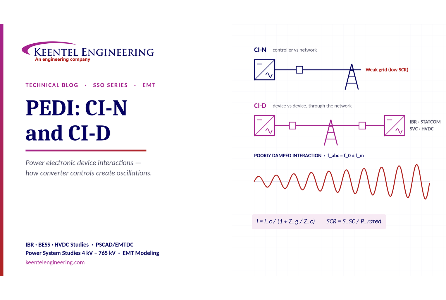
Learn power electronic device interactions (PEDI), including CI-N and CI-D, weak-grid stability, SCR, EMT studies, impedance analysis and mitigation for IBRs.
By SANDIP R PATEL
•
October 3, 2026
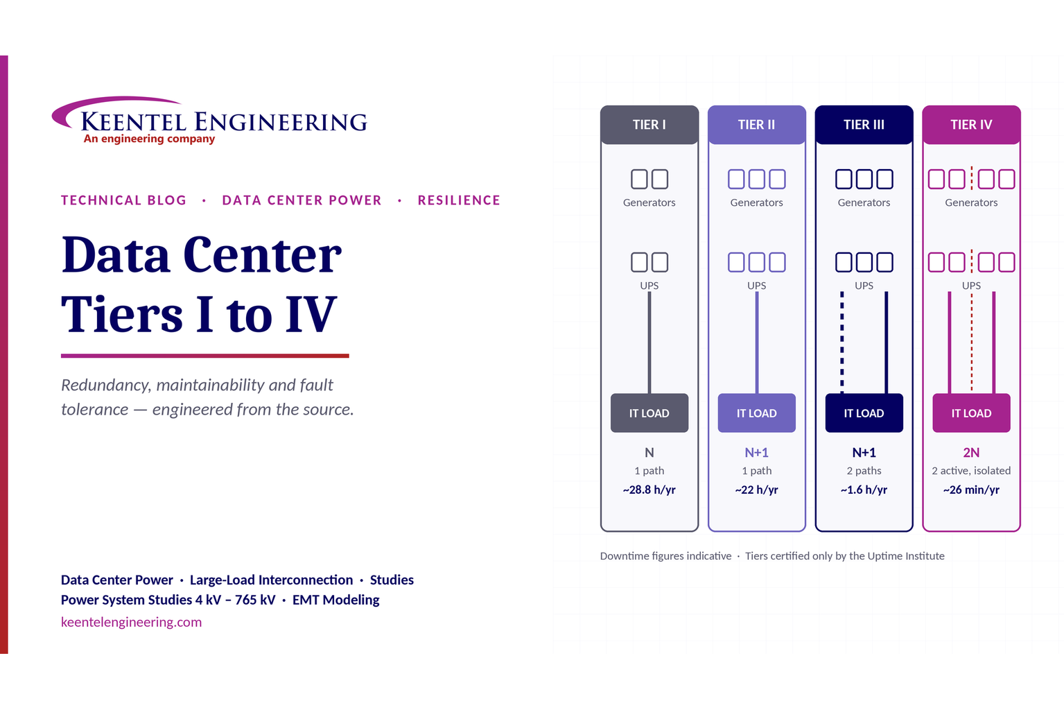
Compare Data Center Tiers I–IV, including redundancy, uptime, Tier III concurrent maintainability, Tier IV fault tolerance, UPS, generators and power design.

By SANDIP R PATEL
•
October 3, 2026
Learn how BESS supports grid stability through fast frequency response, voltage support, oscillation damping, black start, grid-forming controls and EMT studies.
By SANDIP R PATEL
•
October 3, 2026
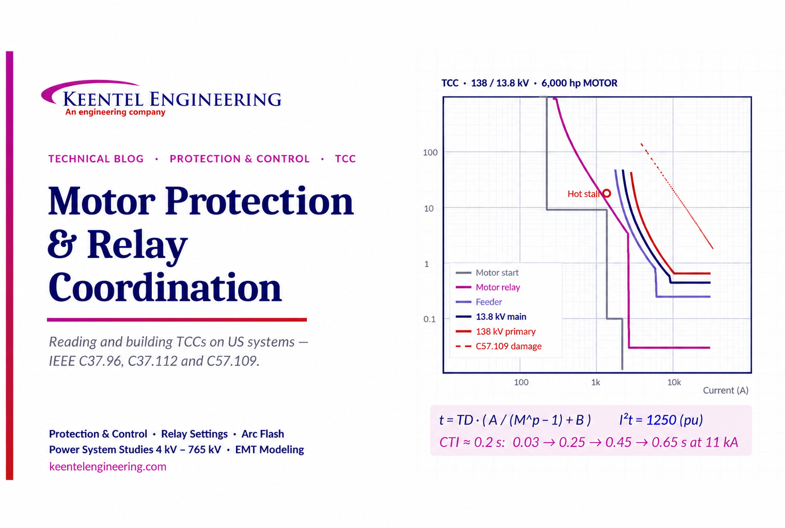
Learn motor protection and relay coordination using TCC curves, IEEE standards, transformer damage limits, CTI settings and a 138/13.8 kV example.

By SANDIP R PATEL
•
September 30, 2026
Learn NERC and ERCOT compliance requirements for natural gas power plants, including GO/GOP obligations, O&P standards, GADS reporting, and audits.





