A Coordinated Electric System Interconnection Review—the utility’s deep-dive on technical and cost impacts of your project.
Challenge: Frequent false tripping using conventional electromechanical relays
Solution: SEL-487E integration with multi-terminal differential protection and dynamic inrush restraint
Result: 90% reduction in false trips, saving over $250,000 in downtime
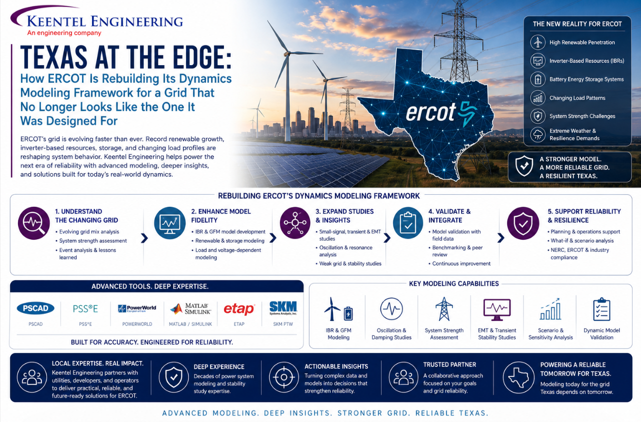
Texas at the Edge: How ERCOT Is Rebuilding Its Dynamics Modeling Framework for a Grid That No Longer Looks Like the One It Was Designed For
May 16, 2026 | Blog
The Grid Has Changed. Has the Modeling Kept Up?
Sometime around 2021, ERCOT's planning engineers noticed something uncomfortable: the tools and models they had used for decades were increasingly struggling to represent a grid that now drew nearly forty percent of its energy from wind and solar, hosted hundreds of inverter-based resources, and was about to receive a tidal wave of data centers demanding hundreds of megawatts each at single points of interconnection. The models were not wrong. They were just designed for a different world.
That recognition has produced a sustained, multi-year effort to redesign the foundational modeling and data collection processes that underpin every stability study, every interconnection assessment, and every reliability determination made for the Texas grid. This blog synthesizes four primary technical documents — the DWG Procedure Manual Revision 24, the ERCOT SSR Study Scope Guideline, the LEL Modeling Approach presentation, and the DWG Large Load Data Survey Version 2 — to tell the story of what is changing, why it matters, and what stakeholders operating in the ERCOT interconnection need to do about it.
Part 1: The Foundation — What the DWG Actually Does and Why It Matters
The Dynamics Working Group is not a committee that meets to discuss policy. It is an engineering body that builds, maintains, and validates the simulation databases that tell ERCOT whether the Texas grid will survive a fault, a sudden generator trip, or a regional voltage collapse. Every flat start case — the simulation-ready snapshot of the grid at a specific future operating condition — that ERCOT uses for planning assessments flows through the DWG.
The DWG operates under a tight annual cycle. After the Steady State Working Group posts its base cases in May, the DWG begins layering dynamic models on top of the static network representation. By December, three flat start cases must be ready: a near-term on-peak case three years out, a near-term off-peak case four years out, and a long-term on-peak case seven years out. These cases then form the foundation for the planning assessments required under NERC Standard TPL-001-4 and the updated TPL-001-5.1, which became effective in July 2023.
Membership in the DWG carries real obligations. Every NERC Transmission Planner operating within the ERCOT footprint must have at least one designated DWG member who is an employee of a registered Transmission Service Provider. TSPs that fail to provide a representative are reported to the Reliability and Operating Subcommittee monthly. The DWG is not optional participation — it is a compliance function.
The confidentiality of the data the DWG handles is significant. Dynamic data and dynamic study cases are treated as protected information under Nodal Protocol Section 1.3. They are distributed only to DWG members. Designated Agents — outside parties acting on behalf of a member — must have Non-Disclosure Agreements in place and must be formally nominated and tracked on the DWG roster. This confidentiality architecture reflects how sensitive the detailed modeling of the Texas grid's dynamic behavior actually is.
Part 2: The Software Transition That Is Reshaping Everything
Perhaps the single most operationally urgent change in the current DWG framework is the transition from PSS/E Version 35 to Version 36. The DWG's current planning model runs on PSS/E v35. The transition to v36 is scheduled for June 2026, at which point the 2026/2027 DWG Flat Start Case will be built and published in the new version.
This matters enormously for any Resource Entity or Interconnecting Entity that has submitted or is about to submit dynamic models. All user-defined models — DLLs, object files, dynamic data files — that were compiled for PSS/E v35 are not compatible with v36. The DWG Procedure Manual is explicit: models compatible with Version 36 must be submitted prior to June 1, 2026. During the transition period, entities are required to provide user-defined models for both versions simultaneously.
The operations model side of the house runs on a different platform entirely: Powertech DSATools TSAT Version 22. This creates an additional modeling obligation for entities whose PSS/E models use user-defined models. TSAT User Defined Models must be provided in TSAT UDM format with associated DLL files, and they must be able to directly read PSS/E format .dyr data files. The TSAT models must be tested with both bus-number-based and equipment-name-based case setups, including a space character in equipment names to verify compatibility with ERCOT's naming conventions.
The PSCAD platform, used for electromagnetic transient simulations, adds a third dimension. PSCAD models at Version 4.5 or higher are required for all IBRs, Wind-powered Generation Resources, and inverter-based transmission elements installed on or after January 2015. All PSCAD models are classified as user-written models regardless of their origin, and all must pass the same Model Quality Test requirements as PSS/E and TSAT models. The combination of three simulation platforms, each with its own version requirements and data formats, makes the current modeling environment genuinely complex for entities entering the interconnection queue.
Part 3: The Model Quality Test — The Bar Has Risen Substantially
If there is a single section of the DWG Procedure Manual that every engineer at a generation facility needs to understand deeply, it is Section 3.1.5, the Dynamic Model Quality Test Guideline. The MQT is not a formality. It is a structured engineering validation process with specific pass/fail criteria for each test, and models that fail are placed on an Unacceptable Models List that prohibits their use in DWG flat start cases.
The test matrix has expanded significantly with the emergence of Advanced Grid Support Energy Storage Resources. Conventional IBRs — solar, wind, battery storage without AGS designation — must pass seven core tests: flat start stability, small voltage disturbance response, Low Voltage Ride-Through, High Voltage Ride-Through, small frequency disturbance response, system strength performance across four Short Circuit Ratios, and phase angle jump tolerance in PSCAD. AGS-ESR adds five additional tests on top of this baseline.
The System Strength Test: The New Critical Qualifier
The system strength test deserves particular attention because it has become a significant differentiator in interconnection outcomes. As the ERCOT grid has added more inverter-based resources and retired thermal generation, short circuit ratios at many points of interconnection have declined. A model that performs beautifully at SCR=5 can become unstable or trip at SCR=1.5, revealing a fundamental control design limitation that would not have appeared in earlier, stronger-grid environments.
The test requires models to demonstrate stable operation at four consecutive SCR levels: 5, 3, 1.5, and 1.2. Models must perform acceptably at SCR=3 and above. If a model fails at SCR=1.5, a detailed technical explanation of the limitation is required and a model enhancement is expected. A model that trips at SCR=3 is categorically unacceptable.
For AGS-ESR models, the system strength requirement is even more demanding. The test begins at SCR=10 and steps down through SCR=5, 3, 1.5, and 1.2. The AGS-ESR must remain stable and must not trip or significantly reduce power output at any tested SCR level. This reflects the specific design intent of AGS-ESR: these resources are expected to contribute grid-forming or grid-supporting behavior even in very weak grid conditions.
The AGS-ESR Loss of Synchronous Machine Test: A New Kind of Stability Proof
The Loss of Synchronous Machine test introduced for AGS-ESR is conceptually distinct from everything else in the MQT. It does not test how a resource responds to a fault or a voltage disturbance. It tests whether a resource can sustain voltage and frequency formation after the grid-forming synchronous source it is operating in parallel with suddenly disconnects.
The test uses a duplicate of the AGS-ESR under study as a neighboring plant, a constant-impedance load, and a synchronous voltage source. Three dispatch scenarios bracket the range of realistic conditions. After the system reaches a stable operating point, the voltage source is disconnected without a fault, and both AGS-ESRs must immediately pick up the load, settle frequency within five seconds, and fully damp any oscillations within ten seconds. This test is essentially a validation of grid-forming capability, and it signals where ERCOT believes the grid's future stability will increasingly come from.
Part 4: Subsynchronous Resonance — The Series Capacitor Problem Nobody Talks About Publicly
The ERCOT SSR Study Scope Guideline is a document that most resource developers never encounter until they are told their project requires an SSR study. At that point, they discover it defines an entirely separate analytical universe with its own criteria, its own simulation requirements, and its own timeline for resolution.
Subsynchronous resonance occurs when the natural electrical resonance frequency of a series-compensated transmission system interacts with the mechanical or electrical characteristics of a nearby generator at a frequency below the fundamental 60 Hz. The consequences range from turbine-generator shaft fatigue — which accumulates invisibly over time — to catastrophic torsional instability that can physically damage or destroy a generator shaft.
When Is an SSR Study Required?
A project is identified as requiring an SSR study when its generating unit is electrically close enough to a series capacitor in the ERCOT transmission system that the interaction cannot be ruled out by inspection. The distance that matters is not geographic but electrical: a generator is considered radial to a series capacitor when all of its output must flow through that capacitor bank.
The study scope for conventional synchronous generators covers three distinct phenomena: Induction Generator Effect (the tendency of a generator's sub-synchronous electrical characteristics to create negative resistance conditions), Torsional Interaction (the coupling between electrical resonance and the mechanical torsional modes of the generator-turbine shaft system), and Torque Amplification (the amplification of shaft torques during switching or fault events near resonant frequencies).
IBRs face a different but related phenomenon: Subsynchronous Control Interaction, in which the control loops of power converters interact with the series capacitor resonance to create oscillating currents that can grow in amplitude rather than decay. SSCI events can develop much faster than torsional interactions and can trip multiple resources simultaneously. The 2012 SSCI event in Texas, involving a wind farm and series capacitors, is the canonical real-world example of how fast this can go wrong.
The Contingency Expansion Method
The ERCOT SSR study methodology uses a systematic outward expansion from the worst-case condition. The study begins by identifying the set of contingencies that make the generator radial to the series capacitor — this is the R set. It then evaluates R+1 (one element back in service), R+2, and continues outward until no further combinations show SSR vulnerability. This ensures that the study captures not just the worst-case topology but the full range of credible operating conditions under which SSR interaction could occur.
For IBRs that show SSR vulnerability for six or fewer outages, or that are radial to a series capacitor within six or fewer outages, time-domain electromagnetic transient simulations in PSCAD become mandatory. These EMT simulations must cover both fault and faultless outage scenarios, vary fault location and fault type, and account for varying system strength by testing with different mixes of nearby synchronous generation online.
The Countermeasure Problem
When SSR vulnerability is confirmed, countermeasures must be designed, studied, and verified. For conventional generators, countermeasures typically involve supplemental torsional damping control systems — active control systems that introduce damping torques at the resonant frequencies. For IBRs, SSR filters or modifications to the converter control strategy are more common. In either case, a follow-up study must demonstrate that the proposed countermeasure actually eliminates the vulnerability across the full range of contingencies and sensitivities that showed vulnerability in the initial study. This follow-up study can add months to an already lengthy interconnection process.
Part 5: Large Electronic Loads and the Data Center Interconnection Wave
The most pressing near-term challenge in ERCOT dynamics modeling is one that would have seemed exotic as recently as five years ago: how to represent the dynamic behavior of gigawatt-scale data center loads in grid stability studies. The scale of the challenge is hard to overstate. In 2024 and 2025, ERCOT received interconnection requests for Large Electronic Loads totaling tens of gigawatts of demand. Many of these projects are at advanced stages of the queue. They will energize. The grid models used to study them must accurately represent how they behave.
Why the Existing Model Fails
The Composite Load Model was developed to represent the aggregate dynamic behavior of a typical distribution feeder: a mix of residential appliances, commercial HVAC, small motors, and industrial loads. Its components — induction motors of various sizes, constant power electronic load fractions, distributed generation — are calibrated against decades of field measurements of how distribution load responds to voltage and frequency disturbances.
A hyperscale
data center is not a distribution feeder. Its power electronic load — the AC/DC conversion infrastructure that feeds the servers — responds to voltage disturbances fundamentally differently from induction motors. When voltage dips, induction motors stall and draw excessive reactive current; power electronic loads either ride through with near-constant power consumption (if their UPS systems maintain output) or disconnect entirely and reconnect later. The momentary cessation behavior — the tendency of grid-connected inverters to temporarily stop injecting current during severe voltage dips — is a critical characteristic that the CMLD simply does not model.
The Interim Solution: EPRI UDM v4 + CMLD Split
ERCOT's Dynamic Studies Team has adopted an interim modeling approach that splits each Large Electronic Load into two components based on its actual load composition. The power-electronic portion — the server and compute infrastructure — is represented using the EPRI User-Defined Model Version 4. This model was originally developed to represent electric vehicle charging infrastructure and has been adapted for data center applications. It includes momentary-cessation logic, reconnection settings with configurable time delays, and control structures that reflect the behavior of modern AC/DC power converters.
The cooling portion of the data center — the chillers, cooling towers, computer room air handlers, and variable-frequency drives that manage thermal loads — continues to be represented by the CMLD, which is well-suited to this type of motor-dominated load. If the cooling equipment uses power-electronic drives extensively, the EPRI UDM can represent that portion as well.
The implementation requires physically splitting the load record in the PSS/E network model into two load entries at the same bus: one representing the cooling fraction modeled with CMLD, and one representing the power-electronic fraction modeled with the EPRI UDM. The split ratio comes directly from the data the facility owner provides in the DWG Large Load Data Survey, specifically Question 30 on the percentage of computer/server load versus cooling load.
The Timeline Is Not Negotiable
ERCOT has published firm deadlines for when the interim LEL model data must be submitted, and these deadlines are tied to project milestones rather than a single calendar date. Projects beginning stability studies after January 5, 2026 must submit interim LEL model data from the start. Projects with completed stability studies that are entering the Large Load Queue System Assessment must submit by May 1, 2026. Projects that have completed their QSA and are approaching energization must submit no later than July 1, 2026 — a date that aligns with the energization timeline for projects that received their QSA approval around February 1, 2026. The message is clear: by the time a data center energizes, ERCOT must have an adequate dynamic model of it in the database.
Part 6: The Large Load Data Survey — What Data Centers Must Provide
The DWG Large Load Data Survey Version 2, accepted by the DWG on December 18, 2025, is the primary instrument through which ERCOT collects the technical data needed to build accurate dynamic models of large load facilities. It is 69 questions long, covers facility design and location, load characteristics, equipment data, dynamic model specifications, backup power systems, protection settings, and subsynchronous oscillation risk, and it includes three appendix tables capturing voltage trip, cooling system trip, and reconnection logic in structured formats.
Several sections of the survey deserve particular attention from data center developers and their engineering teams.
Questions 19-24: Load Technical Characteristics
These questions establish the fundamental composition of the load. The distinction between motor load and power-electronic load (Questions 19 and 20) directly determines which models will be used. Question 24 asks specifically whether cyclic load ramping occurs in the subsynchronous frequency range — a critical flag that can trigger an SSO study requirement. Machine learning workloads, in particular, can produce periodic demand oscillations at frequencies that interact with series compensation if the facility is electrically near a series capacitor.
Questions 39-50: Backup Power Architecture
The backup power architecture of a data center is not just an operational consideration — it has profound implications for how the facility appears to the grid during a disturbance. A facility with online-mode UPS systems (where grid power is continuously rectified and inverted before reaching the servers) presents a fundamentally different dynamic characteristic than one with offline-mode UPS (where the grid feeds the load directly through a transfer switch). Question 42 asks for the specific UPS operating mode and requires that the submitted dynamic model reflect that mode's behavior.
Questions 48 and 49 are uniquely relevant to hyperscale data centers with geographically distributed operations: they ask how much computational load could be transferred to a data center outside ERCOT in the event of a grid trip, and how fast that transfer could be accomplished. The implication is significant — if a 400 MW data center can shed 200 MW of load in under one second by shifting workloads to another region, that is a form of demand response that the grid operator needs to understand and potentially rely on.
Questions 51-65: Protection Settings — The Modeling Critical Path
The protection questions are the heart of the dynamic model specification. Tables A, B, and C in the appendix structure the trip and reconnection logic for the IT load, the cooling load, and the reconnection sequence respectively. The example in Table A illustrates the layered nature of the protection: a voltage dip below 0.7 pu lasting more than one cycle triggers a transfer to UPS; if the dip continues beyond one second, the load transfers to the backup generator. A dip below 0.3 pu triggers immediate transfer to the backup generator without waiting.
The reconnection logic in Table C is where the grid impact of a large data center reconnection is determined. A 400 MW facility reconnecting in five seconds returns 80 MW per second to the grid — a demand ramp that the frequency response of the surrounding generation must be able to absorb. If the reconnection is staggered across multiple facilities that all experienced the same event simultaneously, the aggregate reconnection demand ramp could be enormous. This is why ERCOT needs this data: not just to model the trip, but to model what happens afterward.
Conclusion: The Modeling Framework Is a Reliability Infrastructure
The four documents reviewed here represent something larger than a collection of technical procedures. They represent ERCOT's engineering response to a transformation of the Texas grid that has no historical precedent. The grid is moving from a system dominated by synchronous machines with well-understood dynamics to one dominated by inverter-based resources whose stability characteristics depend on software control algorithms rather than physical inertia. It is receiving loads — data centers — whose dynamic behavior under grid disturbances has never been studied at this scale. It is adding energy storage resources that are expected to provide grid-forming services that previously only synchronous generators could provide.
The DWG's updated procedures, the SSR study framework, the LEL interim modeling approach, and the Large Load Data Survey are the engineering tools by which ERCOT is attempting to maintain analytic rigor in the face of this transformation. For
resource developers load interconnection applicants, and transmission planners operating in the ERCOT footprint, understanding these frameworks is not optional. It is the price of participation in one of the most rapidly evolving power systems in the world.
Summary: Key Deadlines and Action Items
| Deadline | Requirement | Applies To |
|---|---|---|
| June 1, 2026 | PSS/E v36 compatible models must be submitted | All REs with user-defined models |
| January 5, 2026 | Interim LEL model data submission begins | LEL projects beginning new stability studies |
| May 1, 2026 | Interim LEL model data submission | Projects entering LL QSA |
| July 1, 2026 | Interim LEL model data submission | Projects post-QSA, pre-energization |
| Within 30 days | Dynamic model update required after any facility change | All REs — ongoing obligation |
| Within 30 days | Resolve data discrepancies after ERCOT written notice | All REs — compliance obligation |
| Annual | DWG members review and update dynamic data | All DWG members / TSPs |
| Annual | UFLS and UVLS relay data submission | All TSPs with UFLS/UVLS programs |
CASE STUDY 1
Large-Scale AI Data Center Campus — Multi-Phase LEL Interconnection
Type: Large Electronic Load |
Scale: ~2,000+ MW phased |
Technology: Power-Electronic Load + Co-located Gas Generation
Situation
A major technology infrastructure developer is executing a multi-phase AI compute campus interconnecting to ERCOT in multiple tranches over a 2026–2027 energization window. Phase 1 is already operational. Phases 2 and 3 are under construction or planned. The campus pairs high-density GPU compute halls with dedicated on-site natural gas turbine generation intended as supplemental and backup power. The facility draws predominantly from the ERCOT grid but the co-located generation complicates how the facility appears dynamically to the grid operator.
The developer has submitted interconnection requests for each phase separately. ERCOT's Dynamic Studies Team has flagged that no adequate dynamic model exists for the power-electronic portion of the load, and the existing Composite Load Model used in prior planning studies does not accurately represent data center behavior during grid disturbances.
Technical Challenges
Challenge 1 — LEL Model Inadequacy
The facility's compute load — approximately 88% of total draw — is pure power-electronic load: AC power is rectified to DC at the facility level before reaching server hardware. This load does not stall like an induction motor during low-voltage events. Instead, it either rides through via UPS systems with momentary cessation of grid-facing current injection, or transfers to backup generation. The CMLD cannot represent either behavior.
Challenge 2 — Load Composition Split
The remaining ~12% of load is cooling infrastructure — chillers, cooling towers, and pump systems — which is motor-dominated and appropriately represented by CMLD. The challenge is that ERCOT requires a single load bus entry to be physically split into two separate load records: one for the power-electronic fraction (EPRI UDM v4) and one for the cooling fraction (CMLD or EPRI UDM depending on cooling drive technology).
Challenge 3 — Co-located Generation Modeling
The on-site gas turbines are synchronous machines and must provide a complete dynamic model package under DWG Procedure Manual Section 3.2.1: generator model, governor model (gas turbine only — not required for steam turbines in combined cycle), exciter model, and power system stabilizer. Explicit voltage and frequency protection relay models must be provided for any relays set to trip within NERC PRC-024 Attachment 1 and 2 no-trip zones.
Challenge 4 — Interaction Dynamics
The interaction between the data center's UPS protection logic and the gas turbine's exciter response during a grid disturbance is a combined-system dynamic that neither the LEL model nor the generation model alone captures. When a voltage dip triggers UPS transfer, the net load at the POI drops suddenly. Simultaneously, the gas turbine's exciter responds to the voltage dip by boosting reactive output. The combined transient at the POI must be studied in the integrated DWG flat start case.
Challenge 5 — PSS/E v36 Transition
All user-defined models must be available in PSS/E v36 format before June 1, 2026. The EPRI UDM v4 availability in PSS/E v36 is still unconfirmed as of the December 2025 ERCOT LEL Modeling Approach presentation.
Required Actions Under ERCOT Framework
Immediate (already past deadline for Phase 1):
- Complete DWG Large Load Data Survey Version 2 for each operational phase
- Submit interim LEL model: split load bus into two entries — EPRI UDM v4 (PEL) + CMLD (cooling)
- Submit complete synchronous generation dynamic model package for gas turbines
Before next phase energization:
- Tables A, B, and C of the Large Load Survey must be completed with actual protection settings not illustrative examples
- Survey Questions 39–50 must document the full backup power switching sequence including: UPS operating mode (Q42), on-site generation dispatch during grid events (Q46), demand-side management participation capability (Q47), and computational load transfer capability to off-ERCOT infrastructure (Q48–49)
- PSS/E v36 model versions must be submitted before June 1, 2026
Ongoing:
- Any firmware update or facility change requires model update within 30 days (DWG Proc. Manual §3.2.2)
- Machine learning workload oscillation characteristics must be characterized in Survey Q67 to determine if SSO study is required
Key Protection Logic (Survey Tables A/B/C)
The most critical technical data for this facility type is the protection trip and reconnection sequence. A representative architecture looks like this:
- Voltage dip below 0.7 pu lasting more than one electrical cycle → transfer IT load to UPS
- Voltage dip continues beyond 1.0 second → transfer from UPS to backup generation
- Voltage dip below 0.3 pu → immediate transfer to backup generation without waiting
- Reconnection from UPS: voltage stable above 0.3 pu and below 1.1 pu for 1.5 seconds → ramp load back at 20% per second (100% in 5 seconds)
- Reconnection from backup generation: voltage stable for 600 seconds → ramp load back at 20% per second
For a 2,000 MW facility reconnecting at 20% per second from UPS, the demand ramp imposed on the surrounding ERCOT system is 400 MW/second. ERCOT's dynamic model of this facility must capture this ramp rate accurately so that planning studies reflect the actual frequency response burden on nearby generation.
Outcome Framework
Successful compliance requires three parallel workstreams: (1) LEL Survey submission with actual protection data in Tables A/B/C, (2) PSS/E and PSCAD dynamic model package split correctly between EPRI UDM and CMLD components with validated parameters, and (3) synchronous generation dynamic model package for co-located gas turbines. The integrated model is then incorporated into the DWG flat start case where combined system behavior is studied. Any model that cannot be validated in the flat start case due to initialization errors or excessive deviation from flat start criteria will not be incorporated into planning assessments.
CASE STUDY 2
Large-Scale Solar + Battery Storage Hybrid — Standard IBR MQT Path
Type: Inverter-Based Resource |
Scale: ~837 MW Solar PV + ~418 MW BESS |
Technology: Utility-Scale Solar with Co-located Two-Hour Storage
Situation
A utility-scale solar developer is bringing online one of the largest photovoltaic installations in the United States in 2026, paired with a co-located battery energy storage system at the same point of interconnection. The solar array and the BESS use separate inverter platforms from different manufacturers. Both are classified as IBRs under ERCOT protocols. The facility connects to ERCOT in central Texas served by a major investor-owned TSP.
The developer's engineering team must navigate two parallel MQT processes — one for the solar PV component, one for the BESS — while also modeling the plant-level controller that coordinates both resources at the shared POI. The timing pressure is acute: the facility is targeting commercial operations in the second half of 2026, and all models must be validated and incorporated into DWG flat start cases before energization.
Technical Challenges
Challenge 1 — Two-Technology MQT Complexity
The solar PV array and the BESS must each be tested through the full IBR MQT suite independently. The solar array uses an aggregate model per registered resource — a single equivalent model representing all inverters and the collector system. The BESS uses a separate model. Each must pass all seven core MQT tests. If either uses a user-defined model for TSAT, a TSAT UDM is also required, with test cases configured both by bus number and by equipment name including a space character.
Challenge 2 — Solar Frequency Response Testing — Headroom vs. No Headroom
The solar array is an Intermittent Renewable Resource. The Small Frequency Disturbance test requires two separate simulations for the frequency drop scenario: one with the model in a curtailed (headroom available) state at 80% dispatch, and one with the model in a power availability (no headroom) state at 80% dispatch. The description of how to configure the IRR model for each state must be included with the test results. A model in the power availability state that erroneously increases power output in response to a frequency drop — despite having no physical headroom — is unacceptable and must be corrected before submission.
Challenge 3 — BESS AGS-ESR Classification
If the BESS's Standard Generation Interconnection Agreement was signed on or after April 1, 2026, AGS-ESR requirements apply under ERCOT protocols NOGRR 272 and PGRR 121. This would add five tests beyond the standard IBR suite: the AGS Small Voltage Disturbance test (reactive response within one electrical cycle), the Frequency Change and Inertia Response test (H ≥ 2.5 seconds), the enhanced System Strength test at SCR levels from 10 down to 1.2, the Phase Angle Jump test in PSCAD with ±10° and ±25° steps, and the Loss of Synchronous Machine test across three dispatch scenarios. The SGIA execution date must be confirmed before MQT scope is finalized.
Challenge 4 — Plant Controller Integration
The plant-level controller coordinates reactive power output from both the solar array and the BESS to maintain the POI voltage within the ERCOT-required reactive capability band. The plant controller model must be included in all MQT testing — not just the individual inverter models in isolation. During LVRT and HVRT events, both the solar plant controller and the BESS inverter respond simultaneously. If the plant controller does not correctly coordinate the combined reactive response, the aggregate facility behavior at the POI may differ significantly from the individual unit test results, causing flat start initialization failures.
Challenge 5 — LVRT Dual Profile Requirement
Both the legacy LVRT profile (continuous low-voltage event per NOG 2.9.1.2) and the voltage dip profile (piecewise dips returning to 1.0 pu between events per NOG 2.9.1.1) must be tested for both the solar array and the BESS. Each profile must be run at both 0.95 lagging and 0.95 leading initial power factor at the POI — four separate simulations per test type per resource component. For the voltage dip profile, the model must inject active current when the applied voltage dip is 0.5 pu and higher, and reactive current injection must be observable immediately or very shortly after each non-zero dip is applied.
Required Actions Under ERCOT Framework
MQT Test Plan (both components):
| Test | Solar PV | BESS (Standard IBR) | BESS (if AGS-ESR) |
|---|---|---|---|
| Flat Start | PSS/E + PSCAD | PSS/E + PSCAD | PSS/E + PSCAD |
| Small Voltage Disturbance | ±3% step, both directions | ±3% step, both directions | AGS criteria: <1 cycle to 90% |
| LVRT Legacy + Voltage Dip | Both, at 0.95 lag + lead | Both, at 0.95 lag + lead | Both, at 0.95 lag + lead |
| HVRT Preferred + Legacy | Both, at 0.95 lag + lead | Both, at 0.95 lag + lead | Both, at 0.95 lag + lead |
| Frequency Response | IRR: headroom AND no-headroom | 80% discharge + 80% charge | AGS inertia test: H ≥ 2.5 s |
| System Strength | SCR 5, 3, 1.5, 1.2 | SCR 5, 3, 1.5, 1.2 | SCR 10, 5, 3, 1.5, 1.2 — all |
| Phase Angle Jump | PSCAD only | PSCAD only | PSCAD: ±10° and ±25° |
| Loss of Sync Machine | Not required | All TSPs with UFLS/UVLS programs | Required — 3 scenarios |
| Unit Model Validation | Hardware testbench | Hardware testbench | Hardware testbench |
Model Submission Package:
- PSS/E v35 and v36 versions of all user-defined models (v36 required before June 1, 2026)
- TSAT UDM for each component if UDM used in PSS/E
- PSCAD models for both solar and BESS with hardware validation reports
- Completed model guideline checksheet for each model
- Subsynchronous impedance scan 5–55 Hz in 1 Hz increments under 3 system conditions
Unit Model Validation (PSCAD): The hardware testbench must use actual inverter hardware (separate tests for solar inverter and BESS inverter) with typical default settings. The subsynchronous impedance scan must cover: strong system (SCR=10, unity PF), weak system lagging (SCR=1.5, 0.95 lag), weak system leading (SCR=1.5, 0.95 lead). Results delivered as both a plot and a table of R and X in per-unit on the inverter MVA base.
System Strength Test — The Critical Pass/Fail Gate
For both the solar PV and BESS components, the system strength test at SCR=3 is the minimum acceptable performance level. A model that trips at SCR=3 cannot be used in DWG flat start cases and must be redesigned. A model that trips at SCR=1.5 requires a written technical explanation and a model enhancement plan. If the AGS-ESR designation applies to the BESS, stable performance is required at all SCR levels from 10 down to 1.2 without exception — failure at any level is unacceptable for an AGS-designated resource.
Outcome Framework
The critical path for this project's energization is the MQT validation timeline. Both resource components must complete MQT testing, submit results with case files and simulation plots, receive DWG review, and have models incorporated into a flat start case before energization. The model submission, DWG review, and flat start incorporation cycle takes a minimum of one full flat start cycle — typically three to four months. Engineering teams should begin MQT testing at least six months before target energization.
CASE STUDY 3
Wind Generation Near Series-Compensated Transmission — SSR Study Path
Type: Wind Generation (IBR) |
Scale: ~400 MW operating + expansion evaluated |
Technology: Type 3 and/or Type 4 Wind Turbine Generators
Situation
An independent power producer operates a multi-hundred-megawatt wind fleet that interconnects to ERCOT via a 345 kV transmission substation. The facility lies electrically close to series capacitor banks on the CREZ transmission system — the high-voltage backbone built to transmit wind energy from high-resource remote areas to load centers. The developer is evaluating an expansion of the existing fleet. Any new capacity addition must undergo the current full SSR study process, which is substantially more rigorous than the requirements that applied when the original facility was developed.
The facility uses a mix of technology generations: older units use doubly-fed induction generator (Type 3) technology with torsional exposure; newer units use full-converter (Type 4) technology without torsional exposure but with SSCI exposure. This technology mix means the SSR study must cover different phenomena for different turbine types simultaneously.
Technical Challenges
Challenge 1 — Multi-Phenomenon SSR Scope
Type 3 (DFIG) turbines require assessment of all three conventional SSR phenomena: Induction Generator Effect, Torsional Interaction, and Torque Amplification. Type 4 (full converter) turbines require assessment of IGE/SSCI only — no torsional exposure. The SSR study must be structured to apply the correct analytical framework to each turbine type. A study that incorrectly treats Type 4 turbines as requiring TI and TA analysis wastes resources; a study that incorrectly omits TI and TA for Type 3 turbines creates a compliance gap.
Challenge 2 — Series Capacitor Radial Condition Within Six Outages
The facility can be made radial to one or more series capacitor banks within a small number of transmission element outages. Under the ERCOT SSR Scope Guideline, when an IBR is radial to a series capacitor within six or fewer outages, time-domain PSCAD EMT simulations are mandatory — not optional. The contingency screening must begin with the full R set (all contingencies making the plant radial to each capacitor under study) and expand through R+1, R+2, and R+3 tiers until no further combinations show vulnerability.
Challenge 3 — Multiple Series Capacitors
The transmission corridor includes more than one series capacitor installation on different line segments. The SSR Scope Guideline requires that contingency sets capable of simultaneously placing the generation radial to multiple series capacitors be evaluated. The compound effect of two series capacitor banks in a network seen by the wind farm can be significantly more severe than either capacitor in isolation, because the combined subsynchronous resonance frequency may align more closely with a torsional modal frequency or converter control bandwidth.
Challenge 4 — PSCAD Model Accuracy at Subsynchronous Frequencies
SSCI is fundamentally a subsynchronous phenomenon. The PSCAD model's accuracy at frequencies from 5 to 55 Hz is far more critical for SSR studies than for the standard MQT. The Unit Model Validation subsynchronous impedance frequency scan — from 5 to 55 Hz in 1 Hz increments under three system conditions — provides the frequency-domain characterization needed to identify the specific frequencies at which SSCI risk is highest. If the hardware testbench scan shows unexpectedly high negative resistance regions at certain subsynchronous frequencies, these must be investigated before the full PSCAD SSR study is run.
Challenge 5 — Generator Trip Masking Underlying SSR
During time-domain EMT simulations, wind turbines may trip due to their protective relaying before any growing SSCI oscillation is visible. The SSR Scope Guideline specifically addresses this: if the generator trips during a simulated event, the study must be rerun either with generator protection disabled, or with a fictitious metal oxide varistor or arrester added to the series capacitor to artificially limit the transient severity and keep the turbines online long enough to observe whether subsynchronous oscillations are growing. A study that reports "no SSR concern" solely because the turbines tripped before the oscillation developed is methodologically flawed.
SSR Study Methodology — Step by Step
Step 1 — Frequency Scan Analysis (all cases)
Perform frequency scan from generator terminal (or POI) to identify subsynchronous resonance conditions. For IGE/SSCI: examine total combined impedance of generator and grid. If total resistance is negative at the frequency where total reactance crosses zero (from negative to positive with increasing frequency), the scenario has IGE/SSCI vulnerability. For TA: if a 5% or greater reactance dip occurs within ±3 Hz of a torsional modal frequency, investigate further with detailed TA analysis.
Step 2 — Contingency Tiers
- R: all contingencies making the facility radial to the series capacitor(s)
- R+1: all single-element restoration combinations
- R+2: all two-element restoration combinations showing vulnerability in R+1
- R+3: all three-element restoration combinations showing vulnerability in R+2
- Continue until no further tier shows vulnerability
Step 3 — Sensitivity Analysis
For each vulnerable contingency combination, run sensitivities for:
- Switched shunt status (in/out)
- Series capacitor staging/bypass status (for Type 3 turbines)
- Nearby generator status (modeling nearby synchronous generation online vs. offline)
- Plant dispatch: 100% units at 100% dispatch unity PF; 100% units at 10% dispatch leading; 100% units at 10% dispatch lagging; 50% units at 20% dispatch
Step 4 — Time-Domain EMT Simulations (mandatory for this facility)
- Both fault-induced and faultless outage scenarios
- Fault location: near series capacitor AND near POI (when electrically distant)
- Fault types: three-phase AND single line-to-ground
- Rerun with protection disabled if turbines trip before oscillation is observable
- Track voltage across series capacitor(s) and POI voltage (RMS and instantaneous)
Step 5 — TA Detailed Analysis (Type 3 only, if screening triggered)
- Calculate Fatigue Life Expenditure using manufacturer's FLE curves
- Acceptance criterion: FLE < 50%
Pass/Fail Criteria Summary
| Phenomenon | Screening Criterion | Acceptance |
|---|---|---|
| IGE/SSCI | Negative total resistance at reactance zero-crossing | Must be positive (or with margin) |
| Torsional Interaction | Sum of De + Dm negative at modal frequency ±1 Hz | Must be non-negative |
| Torque Amplification | Candice5% reactance dip within ±3 Hz of modal frequency | FLE < 50% in detailed analysistes |
| Time-Domain (EMT) | Growing oscillation post-disturbance | Well-damped; ride-through per NOG 2.9.1 |
Countermeasure Planning
If SSR vulnerability is confirmed for any contingency-sensitivity combination, a countermeasure study is mandatory. The countermeasure must be demonstrated effective across the full set of vulnerable combinations — not just the worst case. Common countermeasures for wind IBRs: SSR filters implemented in converter control software; modifications to the converter's current control loop bandwidth; or supplemental subsynchronous damping controllers. Each countermeasure option requires a follow-up PSCAD simulation campaign that can extend the interconnection timeline by three to six months. Budget and timeline allowance for countermeasure development should be built into every project in an SSR-exposed transmission corridor.
CASE STUDY 4
Battery Energy Storage with Grid-Forming Controls — AGS-ESR Compliance Path
Type: Energy Storage Resource |
Scale: 400 MW / 800 MWh |
Technology: Standalone BESS with Advanced Grid Support Controls
Situation
An energy infrastructure developer has commissioned a utility-scale battery energy storage system designed from the outset with grid-forming control capabilities. The facility's SGIA was signed after April 1, 2026, making AGS-ESR compliance mandatory under ERCOT protocols NOGRR 272 and PGRR 121. The developer's business model combines the BESS with data center power supply architecture — positioning the storage asset as a reliability buffer between the ERCOT grid and co-located power-electronic load.
The project must simultaneously satisfy the full AGS-ESR MQT protocol for the generation-side registration and, where a co-located data center load is present, the DWG Large Load Data Survey requirements for the load-side registration. The combined compliance burden is the most demanding in ERCOT's current framework.
Technical Challenges
Challenge 1 — AGS-ESR MQT Scope — Five Additional Tests
Beyond the seven standard IBR tests, the AGS-ESR designation adds five tests that probe capabilities conventional IBRs are not required to demonstrate:
AGS Small Voltage Disturbance Test (§3.1.5.11): The instantaneous reactive power output must respond within one electrical cycle to reach 90% of the initial change magnitude. For a 400 MW BESS, a 3% voltage step down requires at least 12 MVAr of reactive response within 16.7 milliseconds. This is not a droop response — it is a near-instantaneous grid-forming reactive injection requirement.
Frequency Change and Inertia Response Test (§3.1.5.12): The equivalent inertia constant H must exceed 2.5 seconds. H is calculated as 60 × ΔE where ΔE is the area under the per-unit power curve from 0 to 0.5 seconds during a 1 Hz/s RoCoF event. For a 400 MW BESS, the control system must inject measurable active power within tens of milliseconds of detecting the frequency ramp — behavior achievable only with a virtual inertia control algorithm that emulates the swing equation of a synchronous machine.
AGS System Strength Test (§3.1.5.13): The standard IBR system strength test covers SCR 5, 3, 1.5, and 1.2. The AGS version begins at SCR=10 and steps down through SCR=5, 3, 1.5, and 1.2. The facility must remain stable and must not trip or significantly reduce power output at any tested SCR level. There is no provision for "technical justification" of failure at any SCR level for AGS-ESR resources — the requirement is unconditional stability across the entire range.
AGS Phase Angle Jump Test (§3.1.5.14): Conducted in PSCAD only. The test applies ±10° and ±25° instantaneous voltage phase angle jumps. For the ±10° jump, the peak active power change must be at least 0.2 pu (20 MW for a 100 MW rated unit) opposing the angle change, within one electrical cycle. For the ±25° jump, the peak response must be at least 0.5 pu (50 MW). This test validates that the grid-forming control can detect and oppose angle disturbances with the speed and magnitude required to stabilize the grid during switching events.
Loss of Synchronous Machine Test (§3.1.5.15): The most conceptually novel test in the MQT framework. A duplicate of the AGS-ESR under test represents a neighboring facility. Both AGS-ESRs operate in parallel with a synchronous voltage source supplying a constant-impedance load. Three scenarios are tested across the range of operating conditions. After stable operation is achieved, the synchronous source disconnects without a fault — and both AGS-ESRs must immediately sustain the load, settle system frequency within five seconds, and fully damp all oscillations within ten seconds. Active and reactive power from each unit must move immediately to meet the load requirement, with 90% of the initial change within one electrical cycle.
Challenge 2 — Virtual Inertia Tuning Is a Design Constraint
Achieving H ≥ 2.5 seconds in the inertia test is not a parameter adjustment — it requires a control architecture capable of emulating synchronous machine inertia at the inverter level. The virtual inertia algorithm must detect rate-of-change-of-frequency, compute the proportional active power injection, and command the inverter within the response time window required by the test. If the control firmware does not include this capability, it cannot be added by parameter tuning alone.
Challenge 3 — PSCAD Model Accuracy for Phase Angle Jump
The Phase Angle Jump test requires the PSCAD model to accurately represent the inverter's current limiting behavior during angle transients that can push the inverter beyond its maximum current rating. The test criteria acknowledge this: if the current limit is reached during a ±25° jump, the criteria may not apply, but the active power must still return to its pre-disturbance level in a stable manner. The PSCAD model must accurately represent the current limiter and the control response under current-limited conditions — a modeling fidelity level that exceeds what is typically required for standard IBR flat start cases.
Challenge 4 — Co-located Load Survey Integration
Where the BESS supplies a co-located data center, the developer must simultaneously complete the DWG Large Load Data Survey Version 2. The protection coordination between the BESS inverter protection and the data center UPS protection must be documented in Survey Tables A, B, and C. The voltage thresholds at which the data center transfers from grid to UPS must be consistent with the BESS's own low-voltage ride-through capability — if the data center transfers at 0.7 pu but the BESS trips at 0.75 pu, the BESS would disconnect before the UPS transfer completes, creating an uncontrolled load event.
Challenge 5 — Reconnection Demand Ramp at Scale
After a grid disturbance during which the data center operated on UPS, reconnection of a 400 MW facility at 20% per second imposes an 80 MW/second demand ramp on the surrounding ERCOT system. If the BESS simultaneously begins recharging during this window, the net demand increase at the POI could be significantly higher. The dynamic model must capture both the load reconnection ramp (from the LEL survey Table C parameters) and the BESS recharge initiation logic to accurately represent the aggregate POI demand trajectory during post-disturbance recovery.
AGS-ESR MQT Test Sequence and Criteria
| Test | Setup | Pass Criterion |
|---|---|---|
| Flat Start | 20-second no-disturbance run | All channels within acceptable deviation band |
| AGS Small Voltage Disturbance | Zero impedance source, max discharge, ~0 MVAR initial | Reactive response ≥ 0.03 pu within 1 cycle; sustained >6 cycles |
| LVRT Legacy + Voltage Dip | POI connected to controllable infinite bus, both PF conditions | No momentary cessation; reactive injection immediately observable |
| HVRT Preferred + Legacy | POI connected to controllable infinite bus, both PF conditions | Reactive absorption within 0.5 seconds of HV inception |
| AGS Frequency & Inertia | SCR=3, X/R=6, zero initial active power | H ≥ 2.5 seconds; frequency settles stably |
| AGS System Strength | SCR=10 stepping to 5, 3, 1.5, 1.2 with 4-cycle fault between each | Stable and no trip at all SCR levels |
| AGS Phase Angle Jump | PSCAD only, SCR=3, X/R=6, max discharge | ±10°: ≥0.2 pu response within 1 cycle; ±25°: ≥0.5 pu |
| Loss of Synchronous Machine | PSCAD, 3 scenarios, duplicate AGS + constant impedance load | Frequency settles within 5 sec; fully damped within 10 sec |
| Unit Model Validation | Actual inverter hardware + PSCAD model parallel | Hardware and model match; SSI scan 5–55 Hz |
Loss of Synchronous Machine Test — Three Required Scenarios
| Scenario | Project Plant | Duplicate Plant | Load |
|---|---|---|---|
| 1 | 0.3 pu discharging | 0.1 pu discharging | 1.3 pu |
| 2 | 0.6 pu charging | 0.4 pu charging | 0.7 pu |
| 3 | 0.0 pu | 1.0 pu discharging | 1.65 pu |
All values expressed on project plant rating base. Load power factor 0.95 lagging. Synchronous source disconnects without fault at stable operating point. Simulation continues minimum 10 seconds post-disconnection.
Outcome Framework
An AGS-ESR project that completes all nine tests successfully — including all three Loss of Synchronous Machine scenarios in PSCAD — has demonstrated genuine grid-forming capability that ERCOT can rely on in planning studies. This is the regulatory value proposition: an AGS-ESR that passes the full protocol can be credited in flat start cases with contributing virtual inertia and grid-forming voltage support that partially offsets the retirement of nearby synchronous generation. A project that fails the inertia test or the Loss of Synchronous Machine test must return to control design, rerun the failed tests, and resubmit — adding months to the interconnection timeline. Engineering investment in virtual inertia control design before MQT testing begins is far less costly than redesign after initial test failure
Advanced Technical FAQ
The following questions and answers are drawn directly from the technical content of the four ERCOT source documents. They are organized by subject area and are intended for engineers, project developers, and regulatory professionals who need precise, actionable answers to complex modeling and interconnection questions.
A. PSS/E Version Transition
Q1. Our company submitted PSS/E v35 DLL models last year. Do we need to resubmit for v36, and by when?
Yes, you must resubmit models compatible with PSS/E v36 prior to June 1, 2026. The DWG Procedure Manual Rev. 24 is explicit that during a PSS/E version transition, the previous version user-defined models shall also be provided until a full transition is completed — meaning you must supply both v35 and v36 compatible DLLs simultaneously during the transition period. The 2026/2027 DWG Flat Start Case will be built and posted in PSS/E v36. Any model not available in v36 format by June 2026 will not be incorporated into that flat start cycle, which has downstream compliance implications under NERC MOD-032-1.
Q2. What exactly is included in the v36 model submission package?
A complete PSS/E user-written model submission must include: the DLL file compiled for the target PSS/E version, a model manual containing control block diagrams, design logic, parameter descriptions, a list of parameters commonly tuned for site-specific settings, and procedures for using the model in dynamic simulations. The DWG also requires a completed model guideline checksheet (available on the ERCOT Resource Entity webpage) to be submitted alongside the model. For TSAT, the submission must additionally include a UDM file and, if required, a TUDM file, with test cases set up using both bus numbers and equipment names.
Q3. The EPRI UDM for LEL modeling — will it be available in PSS/E v36?
As of the December 18, 2025 ERCOT presentation, the availability of a PSS/E v36 version of the EPRI UDM is still to be determined. The current EPRI UDM Version 4 is available in PSS/E v35 and is hosted on the NERC LMWG website. PTI is developing a new standard library model for v36 that would replace the interim UDM approach, but its release date remains unknown and is expected sometime in 2026. Entities planning stability studies that begin after June 2026 should contact ERCOT's Dynamic Studies Team for current guidance on the v36 LEL modeling approach.
B. Model Quality Testing Requirements
Q4. Which MQT tests are required for a battery storage project that does not have the AGS-ESR designation?
A non-AGS battery energy storage resource is classified as an IBR for MQT purposes. Required tests are: Flat Start (Section 3.1.5.2), Small Voltage Disturbance (3.1.5.3), LVRT - both legacy and voltage-di profiles (3.1.5.4), HVRT preferred and legacy curves (3.1.5.5), Small Frequency Disturbance at 80% dispatch and 80% charging (3.1.5.7), System Strength across SCR = 5, 3, 1.5, and 1.2 (3.1.5.8), and Phase Angle Jump in PSCAD (3.1.5.9). TSAT model testing is required only if the TSAT model uses a user-defined model rather than a standard TSAT library model.
Q5. Our solar facility has a STATCOM. How does this affect the MQT test setup?
The STATCOM must be included in the site-specific dynamic model used for all MQT testing. Section 3.1.5.1 specifies that all site-specific dynamic models needed to represent the facility shall be included in the test. The DWG Procedure Manual provides a specific example test circuit for an IBR with a STATCOM, showing the STATCOM connected between the aggregate model and the POI. For static switchable devices within the facility — including on-load tap changers and switchable reactive shunts — an initialization script or logic must correctly initialize for the POI initial conditions, and switching control logic must be included if the device is expected to switch within 45 seconds of a disturbance.
Q6. What constitutes an 'unacceptable' response on the Small Voltage Disturbance test?
The DWG Procedure Manual identifies two categories of unacceptable response for the Small Voltage Disturbance test. First, a model that drives the terminal voltage above 1.1 per unit in response to a voltage step down — causing the generator to trip itself offline — is unacceptable. Second, and more fundamentally, a model that shows no AVR response at all to the voltage step is unacceptable. The acceptable response requires that the plant's AVR moves the reactive output toward maximum lagging in response to a voltage step down, and toward maximum leading in response to a voltage step up, with any resulting oscillations being well-damped. Real power output must be sustained throughout both tests.
Q7. For the LVRT test, what is the difference between the 'legacy' and 'voltage dip' profiles, and which applies to our project?
Both profiles are required for all IBRs, WGRs, and IBTEs. The legacy profile applies the Low Voltage Ride-Through curve specified in ERCOT Nodal Operating Guide 2.9.1.2 — a single continuous low-voltage event ending at 0.9 pu. The voltage dip profile evaluates NOG 2.9.1.1 requirements through a series of separate piecewise voltage dips, each starting and returning to 1.0 pu between disturbances. The dip profile tests the facility's ability to ride through repeated events including voltage dips at 0.5 pu and 0.7 pu levels. Resources not subject to the preferred Voltage Ride-Through requirements of NOG 2.9.1.1 are only required to ride through the first dip of the voltage dip profile, which falls within legacy LVRT requirements. In all cases, both tests must be run at both 0.95 lagging and 0.95 leading initial power factor conditions at the POI.
Q8. What is the AGS-ESR inertia constant requirement, and how is it calculated?
The AGS-ESR Frequency Change and Inertia Response Test (Section 3.1.5.12) requires that the equivalent inertia constant H be greater than 2.5 seconds. H is calculated using the formula: H ≈ 60 × ΔE, where ΔE is the area under the per-unit active power production curve of the ESR from time zero to 0.5 seconds following the application of a 1 Hz/s rate of change of frequency. The test is set up with a SCR of 3 at the connection point with an X/R ratio of 6, with the ESR initially dispatched at zero active power output. The formula effectively measures how much energy the ESR injects in the first half-second of a frequency event — a direct measure of its inertia emulation capability.
Q9. Our wind farm PSCAD model goes unstable at SCR=1.2. Do we fail the system strength test?
Not necessarily, but consequences depend on the SCR level of failure. Models must provide acceptable responses for SCR=3 and higher — failure at SCR=3 is categorically unacceptable. If the model is acceptable at SCR=3 but fails at SCR=1.5, a written technical explanation of the reason for the limitation must be provided, and a model enhancement should be considered. If the model is acceptable at SCR=1.5 but fails at SCR=1.2, this may be permissible with adequate technical justification. The key distinction is that SCR=3 is the hard minimum for non-AGS IBRs. For AGS-ESR resources, the requirement is stricter: stable performance is required across all tested SCR levels from 10 down to 1.2.
Q10. What does the Unit Model Validation require beyond the MQT?
The Unit Model Validation (Section 3.1.6) applies specifically to PSCAD models and requires validating the PSCAD inverter model against actual inverter hardware testing. This is a separate requirement from the MQT and must be performed by the Interconnecting Entity or Resource Entity. The validation tests are inverter-specific but not required to be site-specific. The hardware testbench must use actual inverter hardware programmed with typical default settings. Tests include voltage step response, voltage ride-through, system strength response, voltage angle step, and a subsynchronous impedance frequency scan from 5 to 55 Hz in 1 Hz increments. The scan must be conducted under three conditions: strong system (SCR=10, unity power factor), weak system lagging (SCR=1.5, 0.95 lagging), and weak system leading (SCR=1.5, 0.95 leading). Results must be provided as both a plot and a table of resistance and reactance values in per-unit on the inverter MVA base.
C. SSR Study Requirements
Q11. How does ERCOT determine whether our project requires an SSR study?
The SSR Study Scope Guideline does not specify a bright-line distance or capacity threshold that automatically triggers a study. Instead, the determination is made by reviewing the electrical proximity of the proposed generation resource to series capacitor banks in the ERCOT transmission system. If the project can be made radial to a series capacitor through credible contingency combinations, an SSR study will be required. The scope and final study are reviewed by the impacted TSP(s), affected RE(s), and ERCOT. If you are in an area of ERCOT with series-compensated lines — particularly in West Texas where significant series compensation exists — you should assume an SSR study is likely and scope for it early in your development timeline.
Q12. For an SSR study on an IBR wind project, what data must we provide?
Under Section 4 of the SSR Scope Guideline, IBR data requirements include: complete collection system details (cable types, lengths, impedances), the number and type of turbines or inverters, supplemental reactive equipment specifications (switchable shunts, STATCOMs, SVCs with their control parameters), and EMT PSCAD models of the turbines and inverters. The PSCAD models must be the same validated models used in the MQT — not simplified representations. If time-domain EMT simulations are required (which they will be if the project is radial to a series capacitor within six or fewer outages), you must also provide a PSCAD study case file for ERCOT's review.
Q13. What is the IGE/SSCI criterion for passing or failing the frequency scan analysis?
The criterion is based on the total impedance of the generator and the grid viewed from the point of study (typically the POI or low side of the GSU transformer). When examining the combined resistance at the frequency where the total reactance crosses zero from negative to positive with increasing frequency — the anti-resonance point — if the total resistance at that crossover is negative, the scenario has IGE/SSCI vulnerability. If the total resistance is positive at the crossover, the scenario is not of concern, though the guideline notes that an extra margin may be appropriate given modeling uncertainties.
Q14. What is the Torque Amplification screening criterion?
The TA frequency scan criterion uses a 5% reactance dip threshold. When examining the total impedance of the generator and the system across the subsynchronous frequency range, if a 5% or greater dip in reactance occurs within ±3 Hz of a mechanical torsional modal frequency, this indicates potential Torque Amplification vulnerability requiring more detailed analysis. The detailed analysis uses Fatigue Life Expenditure as the acceptance criterion: a scenario passes if the FLE resulting from the transient event is less than 50% of the manufacturer's published life expenditure limit for the shaft section under study.
Q15. When are time-domain EMT simulations mandatory for an IBR SSR study?
EMT simulations are generally required in two circumstances: first, when an IBR is radial to a series capacitor within six or fewer transmission element outages (meaning it takes six or fewer contingencies to make the unit fully radial to the capacitor); and second, when an IBR shows SSR vulnerability for six or fewer outages. When EMT simulations are required, they must cover both fault-induced and faultless outage scenarios, test varying fault locations (near the series capacitor versus near the generator when they are electrically distant), test varying fault types (three-phase and single line-to-ground), and account for varying system strength by testing with different combinations of nearby synchronous generators in and out of service.
D. Large Electronic Load Modeling
Q16. Our data center is 500 MW with 65% server/compute load and 35% cooling. How do we implement the interim LEL model?
Following the ERCOT interim approach, you split the single 500 MW load bus entry into two separate load entries at the same bus. Load entry L1 represents the 175 MW cooling fraction (35% × 500 MW) and is modeled using either the CMLD composite load model or the EPRI UDM Version 4, depending on whether the cooling equipment is primarily motor-driven or inverter-driven. Load entry L2 represents the 325 MW power-electronic fraction (65% × 500 MW) and must be modeled using the EPRI UDM Version 4. Both entries must be accompanied by a PSS/E network model representation and, per Q37 of the Large Load Survey, a PSCAD network model representation.
Q17. What parameters does the EPRI UDM Version 4 capture that the CMLD does not?
The EPRI UDM Version 4 specifically models momentary cessation logic — the behavior of power-electronic loads to temporarily cease drawing current during severe voltage disturbances — and reconnection settings with configurable time delays. These two behaviors are the critical gaps in the CMLD for data center representation. When a data center's UPS systems ride through a voltage dip but the grid-interfacing inverters temporarily cease current injection, the aggregate load apparent to the grid fluctuates in ways that the CMLD's motor-centric model cannot reproduce. The reconnection time delay parameters allow the model to represent the staggered reconnection logic that many data center power systems use to avoid simultaneous inrush.
Q18. Question 24 of the Large Load Survey asks about subsynchronous cyclic ramping. What should we say if our facility runs machine learning training workloads?
This question carries significant regulatory weight. Machine learning training workloads, particularly large-scale model training jobs, can produce periodic power demand oscillations as computational jobs start, run, and complete on regular cycles. If these oscillations have frequency components in the subsynchronous range (typically 5–55 Hz, though practically the concern is in the 5–45 Hz range for series capacitor interaction), they can potentially interact with series compensation in the transmission system. You should characterize the expected magnitude of variation in MW or percent of peak demand and the timing in Hz or period in seconds per Q67 of the survey, which asks specifically about oscillation behavior per second, per minute, and per hour. An honest answer here may trigger an SSO study requirement, but providing inaccurate information creates a greater risk of a post-energization reliability event.
Q19. What information about our UPS system does ERCOT actually need for the dynamic model?
ERCOT needs enough information to accurately represent the grid-visible dynamic behavior of the UPS system during and after voltage and frequency disturbances. Specifically: the operating mode (offline, inline, online, or flywheel), including whether an online UPS has an eco-mode bypass switch; the voltage and frequency thresholds and time delays at which the load transfers from grid to UPS (Table A); the voltage thresholds and time delays at which the load transfers from UPS to backup generation (also Table A); and the reconnection logic — voltage thresholds, stable voltage duration required, reconnection time delay, and ramp rate — for returning from UPS to grid (Table C). The cooling system has separate trip and reconnection parameters captured in Table B. If the submitted dynamic model does not reflect the actual UPS operating mode, separate models for each mode must be provided.
Q20. What is the submission deadline if our data center completed its LL QSA and is targeting energization in September 2026?
If your project completed its Large Load Queue System Assessment and the QSA was associated with a February 1, 2026 processing cycle, the interim LEL model data must be submitted no later than July 1, 2026. This deadline is tied to the energization timeline — ERCOT requires that adequate dynamic models exist in the database before a facility energizes, not after. For a September 2026 energization, the July 1 deadline provides a minimum two-month window for ERCOT to incorporate and validate the models. Contact ERCOT's Dynamic Studies Team if your project does not fit neatly into the published QSA cycle timelines.
E. DWG Process and Compliance
Q21. Our TSP has been reporting us to ROS for missing dynamic data. What are our obligations under NERC MOD-032-1?
Under NERC Standard MOD-032-1 (effective July 1, 2015), Resource Entities are responsible for providing models with model parameters that result in a tuned model accurately representing the dynamic performance of the device. The final responsibility for submission and accuracy lies with the RE. If the DWG or ERCOT identifies inappropriate or incomplete dynamic data, you have 30 days from written notification to resolve the discrepancies. The DWG reports unresolved data issues to ROS in its monthly report, which creates a documented compliance record. Persistent failure to provide required data can result in NERC reliability standard compliance actions. ERCOT and the DWG member for your interconnecting TSP may implement an interim model solution, but this does not relieve your obligation to provide accurate data.
Q22. We have a facility change — new inverter firmware from our manufacturer. Do we need to submit updated models?
Yes. Section 3.2.2 of the DWG Procedure Manual requires that dynamic model updates be submitted to ERCOT and the interconnecting TSP within 30 days of any facility change and/or test result that necessitates a model update to accurately reflect dynamic performance. Inverter firmware changes that modify control behavior — particularly protection settings, reactive power control, or frequency response — constitute exactly this type of change. The updated submission must meet the same data requirements as the original new equipment submission under Section 3.2.1, including any applicable MQT testing that demonstrates the new firmware's performance.
Q23. Can a Designated Agent submit data on behalf of our DWG member company?
Yes, with conditions. A Designated Agent may represent a DWG member under a Non-Disclosure Agreement between the Designated Agent and the sponsoring DWG member. The sponsoring DWG member must notify ERCOT of the Designated Agent's identity and role, and the Agent must be added to the DWG email exploder list at the discretion of the sponsoring member. The DWG reviews the list of participating Designated Agents annually. Critically, if a Designated Agent is not on the DWG roster and will be attending a DWG meeting, the sponsoring member must notify ERCOT and the DWG chair and vice-chair at least one week before the meeting. When a Designated Agent no longer represents a member, the sponsoring member is responsible for notifying ERCOT and having the Agent removed from the list.

About the Author:
Sonny Patel P.E. EC
IEEE Senior Member
In 1995, Sandip (Sonny) R. Patel earned his Electrical Engineering degree from the University of Illinois, specializing in Electrical Engineering . But degrees don’t build legacies—action does. For three decades, he’s been shaping the future of engineering, not just as a licensed Professional Engineer across multiple states (Florida, California, New York, West Virginia, and Minnesota), but as a doer. A builder. A leader. Not just an engineer. A Licensed Electrical Contractor in Florida with an Unlimited EC license. Not just an executive. The founder and CEO of KEENTEL LLC—where expertise meets execution. Three decades. Multiple states. Endless impact.
Services

Let's Discuss Your Project
Let's book a call to discuss your electrical engineering project that we can help you with.
About the Author:
Sonny Patel P.E. EC
IEEE Senior Member
In 1995, Sandip (Sonny) R. Patel earned his Electrical Engineering degree from the University of Illinois, specializing in Electrical Engineering . But degrees don’t build legacies—action does. For three decades, he’s been shaping the future of engineering, not just as a licensed Professional Engineer across multiple states (Florida, California, New York, West Virginia, and Minnesota), but as a doer. A builder. A leader. Not just an engineer. A Licensed Electrical Contractor in Florida with an Unlimited EC license. Not just an executive. The founder and CEO of KEENTEL LLC—where expertise meets execution. Three decades. Multiple states. Endless impact.
Leave a Comment
Thank you for contacting us.
We will get back to you as soon as possible.
We will get back to you as soon as possible.
Oops, there was an error sending your message.
Please try again later.
Please try again later.
Related Posts
By SANDIP R PATEL
•
July 28, 2026
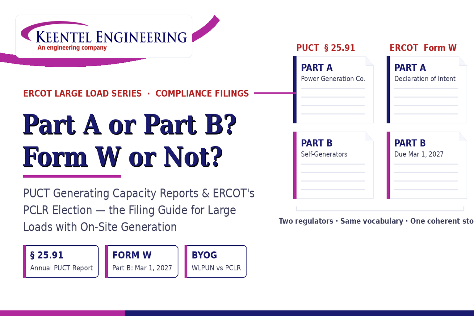
Learn the differences between the PUCT Generating Capacity Report and ERCOT Form W, including Part A vs Part B, PCLR, WLPUN, BYOG projects, and Batch Zero compliance.
By SANDIP R PATEL
•
July 28, 2026
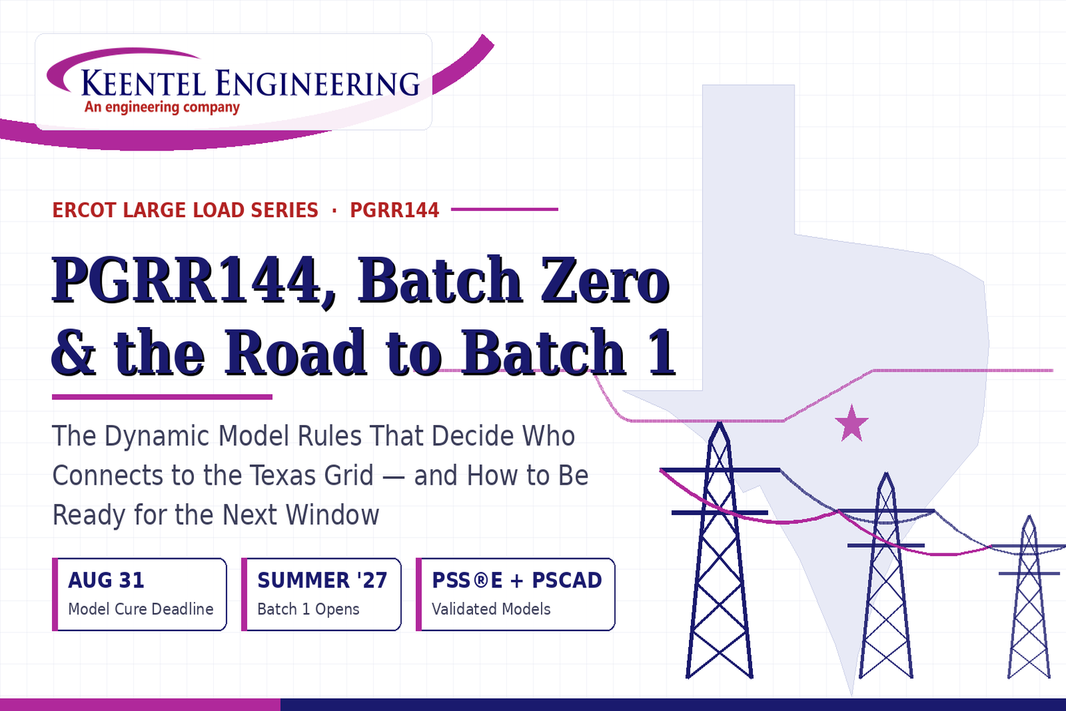
Learn how PGRR144, Batch Zero, and Batch 1 affect ERCOT large-load interconnections, dynamic model requirements, MQT testing, PERC1, and project readiness.
By SANDIP R PATEL
•
July 28, 2026
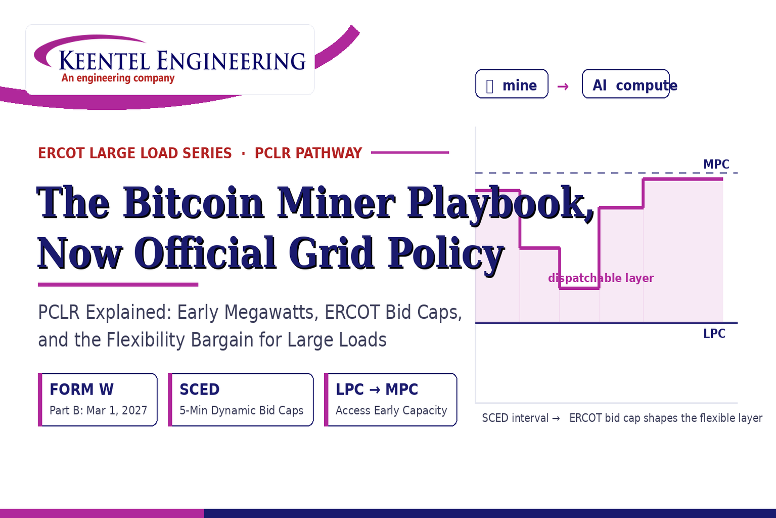
ERCOT PCLR Batch Zero large-load interconnection pathway
By SANDIP R PATEL
•
July 27, 2026
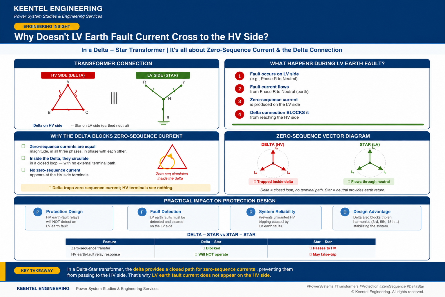
Learn why LV earth-fault current cannot cross a Delta-Star transformer, how zero-sequence current behaves, and what it means for protection design.
By SANDIP R PATEL
•
July 27, 2026
Learn how gas-insulated substations (GIS) improve safety, reliability, and space efficiency with 138 kV design, protection, insulation coordination, and real-world case studies.

By SANDIP R PATEL
•
July 25, 2026
Learn how Class I–IV electrical systems, defence-in-depth, standby and emergency power, DC systems, protection, and load transfer ensure nuclear power plant safety.
By SANDIP R PATEL
•
July 24, 2026
Learn GIS substation safety best practices, SOPs, commissioning, maintenance, interlocking, earthing, and testing to improve grid reliability and uptime.
By SANDIP R PATEL
•
July 23, 2026
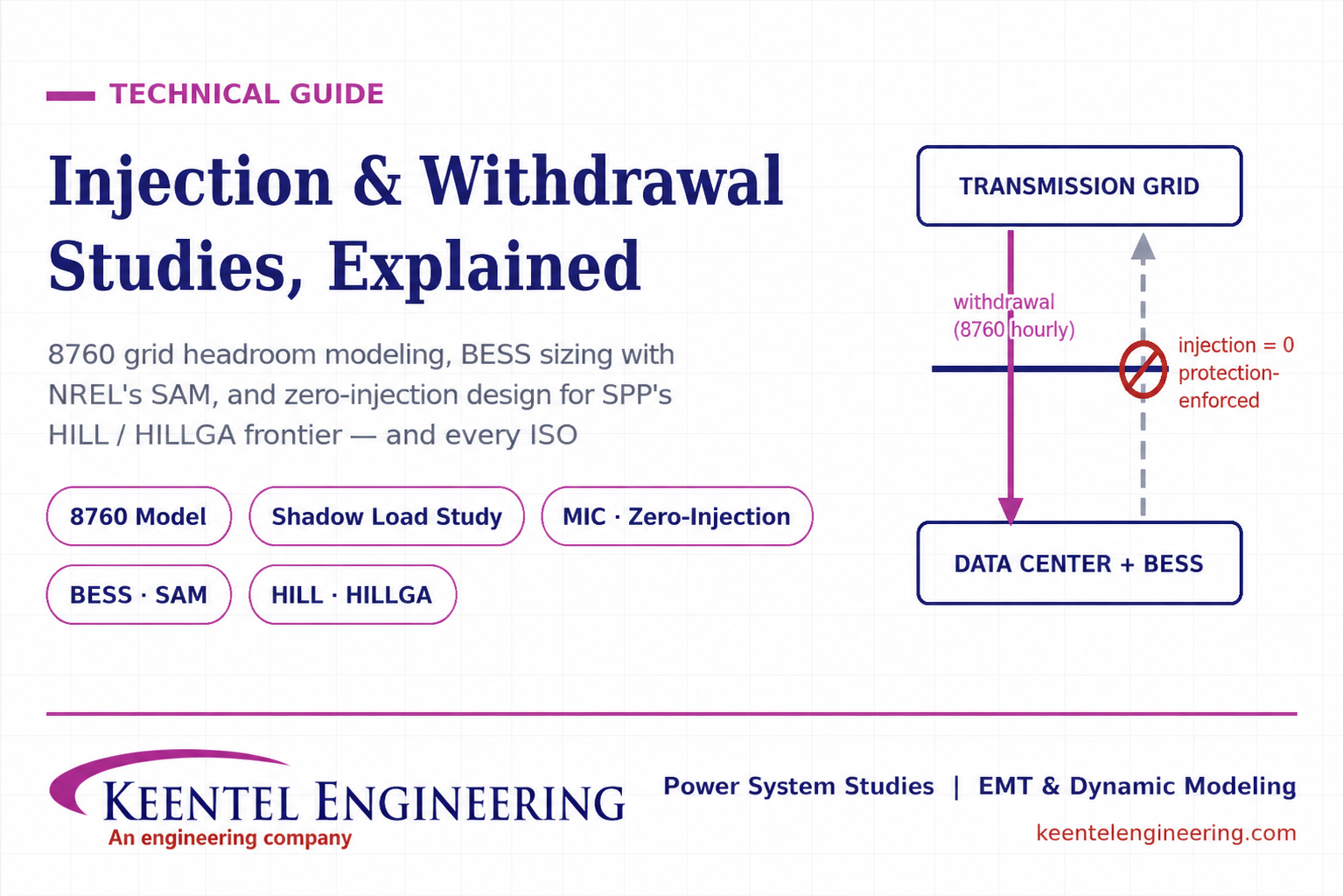
Learn how injection and withdrawal studies, 8760 headroom modeling, zero-injection engineering, and SPP HILLGA improve large load grid interconnections
By SANDIP R PATEL
•
July 21, 2026
Learn how an 8760 withdrawal study models hourly grid headroom and uses SAM-based BESS sizing for large-load interconnection projects.