A Coordinated Electric System Interconnection Review—the utility’s deep-dive on technical and cost impacts of your project.
Challenge: Frequent false tripping using conventional electromechanical relays
Solution: SEL-487E integration with multi-terminal differential protection and dynamic inrush restraint
Result: 90% reduction in false trips, saving over $250,000 in downtime
NERC Draws the Line on Computational Load Risk: What You Need to Do Now
May 8, 2026 | Blog
The Grid Is Under a New Kind of Stress
For decades, the North American bulk power system was built around loads that were large in aggregate but individually predictable — industrial motors, commercial HVAC, residential appliances. Grid operators understood how they behaved. They ramped slowly, they responded predictably to disturbances, and they had decades of operational history behind them.
Then came the data center boom. And with it, AI training clusters, cryptocurrency mining farms, and hyperscale compute facilities capable of shedding or absorbing hundreds of megawatts in a matter of seconds — not minutes, not hours. Seconds.
NERC's Large Loads Working Group has spent two years documenting what the industry has been quietly watching: these facilities are connecting to the grid faster than the regulatory and operational frameworks can handle them. Two types of real, documented incidents crystallized the urgency. First, voltage-sensitive load reductions where multiple large computational facilities simultaneously cut demand during a normally cleared fault — a fault that did not even interrupt their service. Second, sub-synchronous power oscillation events traced directly to computational facilities in the ERCOT and Dominion service territories.
NERC's response arrived in the first week of May 2026 as two documents published simultaneously, each targeting a different layer of the problem.
What NERC Released
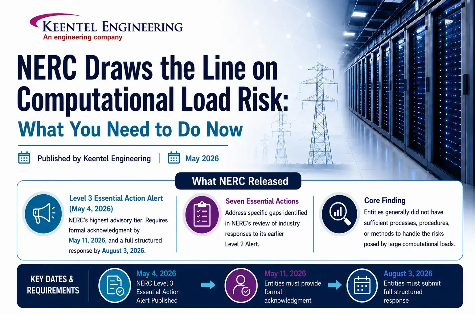
The Level 3 Essential Action Alert
(May 4, 2026) is the most urgent document. A Level 3 Alert is NERC's highest advisory tier. It targets registered entities — Transmission Planners, Planning Coordinators, Transmission Owners, Balancing Authorities, Reliability Coordinators, and Transmission Operators — and requires formal acknowledgment by May 11, 2026, and a full structured response by August 3, 2026. It contains seven Essential Actions, each addressing a specific gap NERC found when it reviewed industry responses to its earlier Level 2 Alert. The core finding from that prior review was blunt: entities generally did not have sufficient processes, procedures, or methods to handle computational loads. That was considered acceptable when data centers were a small fraction of load. It is no longer acceptable.
The Reliability Guideline: Risk Mitigation for Emerging Large Loads
(approved April 30, 2026) is broader in scope. It covers all large load types — not just computational facilities — across the full project lifecycle from interconnection application through operations and eventual system restoration. It runs nine technical chapters and is voluntary and non-binding, but NERC strongly urges adoption. More importantly, it functions as the bridge to future mandatory Reliability Standards currently being developed under Project 2026-02, for which a Standard Authorization Request was posted April 1, 2026. Entities that adopt the guideline now will face a significantly smaller compliance gap when those standards become mandatory.
Why Customer-Initiated Load Reduction Is an Existential Grid Risk
Before walking through the specific requirements, it helps to understand the central technical threat driving this entire regulatory push, because it is genuinely different from anything the grid has dealt with before.
When a transmission fault occurs — even one that is successfully cleared within normal protection clearing times, even one that does not interrupt customer service — the voltage dip at a large data center triggers automatic responses in power electronic equipment. Server power supplies, uninterruptible power supply systems, and adjustable speed drives sense the voltage disturbance and respond within electrical cycles. In a large AI training cluster, this may mean thousands of GPU servers simultaneously dropping their computational workloads and switching to battery backup or simply ceasing demand.
This is called a Customer-Initiated Load Reduction, or CILR. A small amount of CILR doesn't threaten the grid. But at a certain megawatt threshold — and that threshold depends on local system strength and inertia — CILR causes the grid's generation to suddenly exceed its load. When generation exceeds load, frequency rises. If the frequency rises fast enough and high enough, generator overfrequency protection relays trip those generators offline. Now you have lost both load and generation, and the system is chasing a cascade.
The entire sequence — fault, CILR, overfrequency, generator trips — can unfold in less time than it takes a human operator to register what is happening on their display.
There is also a newly identified and poorly documented variant of this problem that the guideline specifically calls out. When a shared AI training job runs across multiple geographically separated data centers, a fault affecting only one facility triggers a synchronized workload interruption across all participating facilities — including those hundreds of miles away that experienced no voltage disturbance at all. The interruption of the shared computational process causes all of them to drop load simultaneously. This distributed CILR mechanism has no historical precedent in grid operations and is not captured in any existing NERC Glossary definition or Reliability Standard.
Three variables determine how severe an overfrequency event from CILR becomes: the total magnitude of aggregate CILR, the amount of online synchronous inertia on the system at the time, and the availability of frequency-responsive reserves with downward droop capability. All three must now be modeled and managed explicitly.
The Seven Essential Actions
Essential Action 1 — Dynamic Modeling Requirements (TPs and PCs)
Transmission Planners and Planning Coordinators must develop detailed modeling requirements for computational loads and distribute them to Transmission Owners in their footprint, who must reflect them in their interconnection requirements. The baseline model required is the PERC1 model — Power Electronic Reconnecting and Ceasing — or a model with equivalent or better capabilities.
PERC1 is specifically designed for computational loads. Unlike traditional composite load models, it captures the voltage-sensitive trip and reconnect behavior that drives CILR events. It requires parameters for low-voltage trip thresholds and duration, reconnection voltage and timing, UPS transfer logic, battery backup transitions, and real power ramp rate during reconnection.
Beyond the PERC1 model itself, TPs and PCs must collect a specific set of data from computational load entities. This includes electrical size and power factor on a seasonal basis including forecasted buildout schedules, dynamic characteristics of the computational and cooling loads, load composition broken down as a percentage of IT load versus non-IT load at various loading levels, expected maximum ramp rates both up and down, the settings of all protective devices that could trip the load or reduce its demand, information about on-site generation including battery storage and when it would operate in parallel with the grid, and facility use type — whether the facility is used for AI training, inference, cryptocurrency mining, or traditional cloud workloads. Each use type has meaningfully different behavioral characteristics.
Essential Action 2 — System Studies (TPs and PCs)
TPs and PCs must study their systems with specific additional considerations for computational loads. They must evaluate System Operating Limits or similar operating envelope limitations for how much additional computational load a given area can absorb before voltage or frequency instability becomes a concern. This may include P-V and P-Q analysis, system strength screening, and transient domain limits.
They must identify areas that are specifically vulnerable to instabilities caused by computational loads and develop mitigation measures. And they must identify credible contingencies where the aggregate loss or reduction of computational loads — including CILR events — would cause planning criteria violations, update contingency files accordingly, and communicate the associated megawatt thresholds to Balancing Authorities and Resource Planners.
This last point is a new modeling paradigm for most planning tools. A contingency that involves CILR isn't simply a tripped element — it is a behavioral response to a fault that must be quantified and tracked.
Essential Action 3 — Qualified Change Definitions (PCs)
Planning Coordinators must revise their publicly available definition of "qualified change" — the definition that triggers a new reliability assessment under FAC-002 — to explicitly include computational load. The new definition must capture growth of the computational load above a defined threshold, changes to settings, parameters, or configuration of electrical supply equipment including UPS systems and power distribution units, and repurposing of the facility for a significantly different application.
That last item was specifically motivated by documented cases in ERCOT where facilities received interconnection approval as data centers and subsequently converted to cryptocurrency mining operations. The dynamic behavior of those two use types is sufficiently different that the original interconnection study was no longer valid.
Essential Action 4 — Commissioning Process (TOs)
Transmission Owners must establish formal commissioning processes for computational loads — processes modeled more closely on how generators are commissioned than how traditional industrial loads have historically been handled.
The process must include evaluation of the as-built facility model, including model quality assessment and model verification before the facility is energized. It must include notification to owners of nearby generation facilities, particularly those sharing the same or an electrically close point of common coupling, before any commissioning tests are conducted. Where possible, it must include a full facility load test at rated capacity and a no-load test, both conducted with the actual computational equipment installed and operational — not just the electrical infrastructure — because server power supplies behave very differently under load than at idle.
Additionally, where feasible, at least a 10% voltage deviation in both directions from nominal must be performed while monitoring individual phase currents. This is the closest field approximation to characterizing low-voltage ride-through behavior short of an actual system disturbance. A commissioning checklist must be coordinated between the TO, the computational load customer, the relevant RC, TOP, and BA, and surrounding generator operators where applicable.
Because many large data centers energize in phases over months or years, commissioning steps may need to be repeated each time maximum consumption increases significantly.
Essential Action 5 — Fault Coordination and Ride-Through (TPs, PCs, TOs)
TPs and PCs must study the system and implement corrective actions on the utility side to ensure no non-consequential loss of firm computational load from normally cleared non-bus faults. This requires acquiring facility-level relay settings and protection configurations from computational load entities and using that information to evaluate the response of the load's protection and control systems to simulated faults.
TOs must coordinate with computational load customers on customer-side improvements to maximize ride-through performance up to equipment capability limitations. The goal is to increase voltage stability margins by reducing the amount of CILR that occurs during events the BPS is designed to handle without customer service interruption.
Essential Action 6 — Fault Recording Instrumentation (TOs)
Transmission Owners must install dynamic fault recording devices at computational load facilities, or collaborate with computational load owners to install devices or gain access to existing ones. The requirement encompasses both continuous dynamic disturbance recording at lower resolution and trigger-based digital fault recording at higher resolution.
These devices must be installed at a minimum at the high side of the main power transformer. Specifications for sample rates, recording windows, and triggers should follow PRC-002 and PRC-028 as a baseline. TOs must supply data from these devices to TPs, PCs, RCs, Regional Entities, and the ERO upon request for event analysis and root cause analysis.
Essential Action 7 — Interpersonal Communication (TOPs, RCs, BAs)
Transmission Operators, Reliability Coordinators, and Balancing Authorities must establish interpersonal communication capabilities with computational load operators 24/7 contact, voice and SCADA-based channels — to issue instructions, orders, and information to prevent BES Emergencies. This mirrors the communication requirements that already apply to generator operators but have not historically been required of load customers.
The Reliability Guideline: Nine Chapters of Risk Mitigation
Beyond the seven Essential Actions, the Reliability Guideline covers the full spectrum of what reliable large load integration requires. Here is the practical takeaway from each chapter.
Chapter 1 — Data Collection and Modeling
Establishes a three-stage data collection framework tied to the project lifecycle: an interconnection evaluation stage, an integration and commissioning stage, and an ongoing operations stage. Each stage has defined minimum data requirements. The chapter also establishes the model verification and validation framework — distinguishing between model quality assessment, model verification (confirming model parameters match as-built design), and model validation (confirming simulation results match measured field performance). Large load entities must attest that model parameters represent actual installed equipment, not manufacturer defaults.
Chapter 2 — Interconnection Studies and Processes
Outlines the comprehensive study process TPs and PCs must establish, including steady-state, transient dynamic, and electromagnetic transient studies where warranted. It provides specific EMT screening criteria — when PSPD simulations fail to converge, when large power electronic devices are present, when short-circuit ratios fall at or below approximately 2, when series capacitors are present, or when nearby large turbine generators could experience subsynchronous torsional interaction with a cyclical load profile. The chapter also addresses triggers for re-study, emphasizing that a change in load type or vendor selection late in the interconnection process may require a completely new dynamic study.
Chapter 3 — Long-Term Planning and Resource Adequacy
Addresses the risk that large loads seek grid connection faster than generation and transmission can be built. Resource Planners must model scenarios where generation additions are delayed relative to load additions. They must incorporate buildout schedules in their studies. They must model the operational flexibility and constraints of large loads — including dispatch constraints, minimum runtimes, time-varying operating limits, and behind-the-meter generation interactions — rather than assuming static load profiles. Loss of load expectation modeling must incorporate transmission delivery limitations and locational risk. Multiple probabilistic RA metrics beyond LOLE and Planning Reserve Margin are recommended.
Chapter 4 — Operations and Balancing
Covers the real-time operations side in detail. Balancing Authorities must incorporate large load variability into regulating reserve and contingency reserve assessments. They must identify the most severe load contingency — including CILR events — and incorporate it into unit commitment and reserve considerations, analogous to how generation most-severe single contingency requirements work in BAL-002 and BAL-003. Transmission Operators must establish protocols for large load outage coordination consistent with IRO-017. Large load entities must submit day-ahead operating plans and 7–10 day demand forecasts and respond to operating instructions issued by RCs, BAs, and TOPs.
Chapter 5 — Stability
Is the most technically dense chapter. It covers voltage disturbance performance requirements including low-voltage and high-voltage ride-through, rate-of-change of frequency ride-through, and phase-jump considerations. It covers overfrequency risk from CILR, establishing that operators must aim to arrest the frequency zenith below 60.5 Hz for the Eastern Interconnection and 60.6 Hz for all other interconnections — noting ERCOT's stricter limit of 60.4 Hz in the transient timeframe. It covers oscillation mitigation for facilities with cyclical demand profiles in the 0.1–2 Hz electromechanical range, specifically citing documented oscillation events at a cryptocurrency mining facility in ERCOT and a data center in the Dominion footprint. And it covers angular stability risks specific to large loads co-located with generation in weak transmission areas, where sudden load trip can leave nearby generators without sufficient export capacity.
Chapter 6 — Power Quality
Addresses harmonic distortion from power electronic loads. Harmonic limits from IEEE Standard 519-2022 should be incorporated into interconnection requirements under FAC-001. Harmonic evaluation studies should assess impact on nearby synchronous generators, existing harmonic filter banks, and overall voltage distortion at the interconnecting substation, up to the 100th harmonic order. If harmonic emissions increase by 10% or more following facility design changes, interconnection studies must be re-performed.
Chapter 7 — Physical and Cyber Security
Establishes a security-by-design approach aligned with CIP-005, CIP-007, CIP-008, CIP-013, and CIP-014. It calls for comprehensive risk assessments integrating physical and cyber threat vectors, security controls built into initial design rather than retrofitted, robust network segmentation between operational technology and IT networks, supply chain cyber security due diligence, and joint incident response plans between utilities and large load operators. Annual security posture reviews are recommended.
Chapter 8 — Resilience, System Restoration, and Load Shedding
Addresses three specific gaps. First, large load growth can dilute UFLS participation percentages below the 25% PRC-006 design basis — TOs must assess whether large loads should be enrolled in UFLS schemes and whether assessment frequency (currently required only every five years) should be increased given that large loads can be constructed in 12–18 months. Second, automatic UFLS percentage monitoring in real time is recommended. Third, blackstart coordination protocols must be established between TOPs and large load entities before an outage occurs — because without pre-established communication paths, large loads cannot be safely incorporated into island energization sequences.
How Keentel Engineering Can Help
Q: What exactly is the PERC1 model and why is it required instead of existing load models?
PERC1 stands for Power Electronic Reconnecting and Ceasing. It was developed specifically because traditional composite load models like CMPLDW were not designed to capture the behavioral characteristics that make computational loads uniquely risky. The critical parameters PERC1 captures that older models miss are the voltage-sensitive trip threshold — the voltage level and duration at which the load disconnects — the reconnection voltage and time delay, the distinction between IT load fraction and non-IT load fraction in determining how much of the facility behaves as power electronics versus as motor load, and the UPS transfer logic including battery backup transition timing and reconnection ramp rate. Essential Action 1 allows TPs and PCs to use a model with "equivalent or better capabilities," and EMT-domain models may be additionally required for weak-grid interconnections or for facilities with large power electronic content. PERC1 parameters must be field-validated — default parameters that do not represent the specific facility are explicitly called out as insufficient. Large load entities must attest in writing that their submitted model parameters represent actual installed equipment.
Q: When is an EMT study required versus a PSPD study sufficient?
The guideline provides specific screening criteria. An EMT study should be performed when PSPD simulations do not converge or fail to demonstrate the reliability concern of interest, when large power electronic devices are present including HVdc lines, large electric arc furnaces, inverter-based resources, or static reactive power devices, when the short-circuit ratio falls at or below approximately 2 (meaning the three-phase fault current available from the system divided by the total apparent power rating of on-site power electronics is very low, indicating weak grid conditions), when series capacitors are in the nearby transmission path, or when large steam, gas, or hydroelectric turbine generators are nearby and the load profile has significant power oscillations in the 5–60 Hz range where subsynchronous torsional interaction risk exists. The SCR of 2 is offered as an example, not a final threshold. For subsynchronous control interaction risk, particularly for large loads near IBRs or connected through series-compensated lines, EMT studies are generally necessary regardless of SCR because PSPD tools cannot represent the relevant high-frequency dynamics.
Q: How must CILR events be represented in TPL-001 contingency files?
CILR events represent a new contingency paradigm for most planning tools. The "element affected" is not just a tripped transmission element — it is a quantified behavioral load response to a fault that must be modeled explicitly. The required steps are: use accurate PERC1 models to determine which fault scenarios would trigger aggregate computational load reductions above the threshold that causes planning criteria violations; update contingency files to include the aggregate CILR MW expected for each relevant contingency, not just the faulted elements; communicate those MW thresholds to BAs for unit commitment and reserve planning; and conduct cluster analyses studying the collective simultaneous response of multiple electrically proximate computational load facilities to a single fault. For existing TPL assessments completed without proper PERC1 models or CILR contingencies, those assessments may need to be updated.
Q: What does the commissioning process specifically require for computational loads?
Essential Action 4 establishes a commissioning paradigm modeled more closely on generator commissioning than traditional industrial load energization. The process must include model quality assessment and model verification of the as-built facility before energization, with the verification report provided to TPs and PCs. Notification of nearby generator operators where those generators share the same or electrically close POI. Where possible, full facility load and no-load testing with actual computational equipment installed and operational, not just the electrical infrastructure, because server power supplies behave very differently under load. At least a plus or minus 10% voltage variation from nominal performed while monitoring individual phase currents — one method is adjusting step-down transformer tap settings. A coordinated commissioning checklist reviewed with the TO, computational load customer, relevant RC, TOP, and BA, covering switching sequences, design prints review, protection system functional testing, SCADA point verification, RAS testing if behind-the-meter generation exists, and in-service load and protection coordination checks. Post-energization verification that all parties have consistent as-built diagrams, SCADA system data, and one-line diagrams showing clearly defined TO versus customer responsibilities. Because many data centers energize in phases, these steps may need to be repeated for each significant increase in maximum consumption.
Q: What fault recording equipment is required and where must it be installed?
At minimum, monitoring should be installed at the high side of the main power transformer. The required equipment types are continuous dynamic disturbance recording for lower-resolution ongoing capture, trigger-based digital fault recording for higher-resolution event capture, and sequence of events recording for timestamped protection system operation logs. PRC-002 and PRC-028 provide baseline specifications for sample rates, recording windows, and triggers, and the same baseline should apply to computational loads. For facilities with oscillation risk — particularly those near synchronous generators or with cyclical AI training workloads — accurate characterization of frequency signals above 5 Hz may require point-on-wave measurements that traditional PMUs cannot provide. The TO may accomplish Essential Action 6 through collaboration with the computational load owner to install devices or gain access to existing equipment inside the facility. The key obligation is that the data must be available to TPs, PCs, RCs, Regional Entities, and the ERO upon request.
Q: What are the overfrequency limits that must be maintained during CILR events?
The guideline establishes that operators must aim to arrest the frequency zenith below 60.5 Hz for the Eastern Interconnection and 60.6 Hz for all other interconnections. These thresholds correspond to the continuous operation zone established in PRC-024 Attachment 1 — above those frequencies, generators are permitted to trip on overfrequency protection after defined time periods, and cascading generator loss can result. ERCOT has set a stricter transient overfrequency limit of 60.4 Hz, specifically because not all generators in its footprint can actually sustain operation at 60.6 Hz. Generator Owners must assess their equipment's actual capability at upper frequency limits and communicate those limits to BAs, TPs, PCs, and RCs for use in large load ride-through analysis under R3 of PRC-024. The frequency ride-through no-trip zone for large loads must also be coordinated with UFLS trip settings, because if loads shed at the same frequency at which UFLS is designed to operate, the programs can interfere with each other.
Q: How does rapid large load growth create UFLS compliance risk under PRC-006?
PRC-006 requires that UFLS programs provide sufficient enrolled load to arrest frequency decline for generation deficits up to 25% of total area load. Compliance is demonstrated by confirming that UFLS-enrolled circuits represent at least 25% of total load. When a large computational load that is not enrolled in UFLS connects to an area, it increases total load without adding UFLS-enrolled capacity, diluting the enrollment percentage. A region that was 28% enrolled with 1,000 MW of total load might fall to 21% enrolled after a 300 MW non-participating data center connects. PRC-006 and PRC-010 require effectiveness evaluations only every five years, but large loads can be constructed in 12 to 18 months. That mismatch means a region could be out of compliance for years before a scheduled assessment catches it. The guideline recommends that PCs dynamically adjust UFLS assessment frequency based on load growth rate or define a total load growth threshold that automatically triggers a new assessment, and that real-time monitoring of the actual UFLS percentage be implemented by TOs, TOPs, and DPs.
Q: What do computational load operators — data centers, mining facilities — need to do if they are not registered NERC entities?
Currently, computational load entities are not required to be registered with NERC and are not directly bound by either document. However, NERC has posted draft registry criteria for a new Computational Load Entity registration category defined as 20 MW or greater, connected at 60 kV, containing more than 1 MW of IT load. If those criteria are finalized, affected facilities become registered entities subject to Reliability Standards. In the meantime, many of the requirements in both documents will flow down to large load customers through interconnection agreements, making voluntary compliance effectively required for interconnection approval. Large load entities should prioritize providing accurate PERC1 model data to their interconnecting utility, implementing ride-through improvements in coordination with their TO and TP, ensuring UPS and power management settings are disclosed and updated to meet area-specific disturbance performance requirements, establishing 24/7 operational contacts with the TOP, BA, and RC, and submitting day-ahead operating plans and 7–10 day demand forecasts. OEMs — manufacturers of IT equipment, server power supplies, cooling infrastructure, and UPS systems — are also explicitly included in the guideline's recommendations and should consider how their equipment's default protection settings interact with the disturbance performance requirements their customers face.
Q: What happens if an entity does not respond to the Level 3 Alert by the August 3 deadline?
The Level 3 Alert does not create new monetary penalty exposure solely for failure to implement the Essential Actions. However, failure to acknowledge by May 11 and submit a response by August 3 is a violation of NERC Rules of Procedure Rule 810, which governs compliance with NERC Alerts. Additionally, if a failure to implement an Essential Action constitutes a violation of an already-approved Reliability Standard — FAC-001, FAC-002, TPL-001, PRC-002, PRC-006 — those violations remain subject to NERC enforcement regardless of the alert's own penalty provisions. FERC will receive an anonymized aggregated report of entity responses, and the results will directly inform how NERC prioritizes the scope and stringency of the mandatory standards being developed under Project 2026-02.
Q: How does the guideline handle oscillation risks from AI training workloads specifically?
Chapter 5 addresses this in detail. AI training workloads are specifically called out alongside electric arc furnaces as the types of large loads most likely to introduce forced oscillations into the BPS. This is because AI training runs in discrete batch cycles — a training iteration begins, thousands of GPUs simultaneously ramp to full utilization, the iteration completes, and the cycle repeats. If the frequency of this cycling falls in the electromechanical range of 0.1 to 2 Hz for inter-area and local modes, it can interact with the natural oscillatory modes of the grid and cause growing or sustained forced oscillations. At higher frequencies, particularly in the 5 to 60 Hz range, there is risk of subsynchronous torsional interaction with nearby generators or subsynchronous control interaction with inverter-based resources. The guideline cites a documented cryptocurrency mining oscillation event in ERCOT and a data center oscillation event in the Dominion footprint as evidence that these are not theoretical risks. AI training data center operators are specifically directed to implement software mitigations — GPU power smoothing — and hardware mitigations including rack-level energy storage to dampen the cyclical power demand pattern. TPs and PCs must establish oscillation attenuation metrics and real power amplitude variation thresholds that loads must meet as interconnection requirements.
Key Dates
Acknowledgement deadline: May 11, 2026 Full response deadline: August 3, 2026 SAR for computational load standards posted: April 1, 2026 Reliability Guideline approved: April 30, 2026
Keentel Engineering provides power systems engineering, transmission planning, protection and control, and grid reliability consulting services. Contact us to discuss how we can support your compliance with the Level 3 Alert and the Reliability Guideline.

About the Author:
Sonny Patel P.E. EC
IEEE Senior Member
In 1995, Sandip (Sonny) R. Patel earned his Electrical Engineering degree from the University of Illinois, specializing in Electrical Engineering . But degrees don’t build legacies—action does. For three decades, he’s been shaping the future of engineering, not just as a licensed Professional Engineer across multiple states (Florida, California, New York, West Virginia, and Minnesota), but as a doer. A builder. A leader. Not just an engineer. A Licensed Electrical Contractor in Florida with an Unlimited EC license. Not just an executive. The founder and CEO of KEENTEL LLC—where expertise meets execution. Three decades. Multiple states. Endless impact.
Services

Let's Discuss Your Project
Let's book a call to discuss your electrical engineering project that we can help you with.
About the Author:
Sonny Patel P.E. EC
IEEE Senior Member
In 1995, Sandip (Sonny) R. Patel earned his Electrical Engineering degree from the University of Illinois, specializing in Electrical Engineering . But degrees don’t build legacies—action does. For three decades, he’s been shaping the future of engineering, not just as a licensed Professional Engineer across multiple states (Florida, California, New York, West Virginia, and Minnesota), but as a doer. A builder. A leader. Not just an engineer. A Licensed Electrical Contractor in Florida with an Unlimited EC license. Not just an executive. The founder and CEO of KEENTEL LLC—where expertise meets execution. Three decades. Multiple states. Endless impact.
Leave a Comment
We will get back to you as soon as possible.
Please try again later.
Related Posts