
A Coordinated Electric System Interconnection Review—the utility’s deep-dive on technical and cost impacts of your project.
Challenge: Frequent false tripping using conventional electromechanical relays
Solution: SEL-487E integration with multi-terminal differential protection and dynamic inrush restraint
Result: 90% reduction in false trips, saving over $250,000 in downtime
The three operating regions you have to design to
| Device | Output vs voltage | Response | Best suited to | Main limitations |
|---|---|---|---|---|
| Mechanically switched capacitor or reactor | Proportional to voltage squared | Seconds; discrete steps; limited switching operations per day | Steady-state reactive supply, voltage profile, loss reduction | No dynamic capability; step voltage change on switching; capability collapses when most needed |
| Static var compensator | Capacitive branches proportional to voltage squared | A few cycles; continuously controllable | Continuous control where cost matters and deep voltage support is not the driver | Square-law capability loss; harmonic filters are part of the plant and interact with the network |
| STATCOM | Approximately proportional to voltage — constant current capability | One to two cycles closed loop; converter response faster still | Voltage stability margin, weak interconnections, fast disturbance recovery, flicker and unbalance compensation | Higher capital cost; converter losses; adds a converter and its control dynamics to the network |
| Synchronous condenser | Governed by machine capability and excitation | Excitation response in the hundreds of milliseconds; inherent inertial response instantaneous | System strength and inertia, short-circuit contribution, black start support | Rotating plant with maintenance and losses; slower controlled response than a converter |
| STATCOM with energy storage | Reactive as a STATCOM, plus real power within the storage rating | As STATCOM for reactive; real power limited by storage | Where a real power deficiency is part of the problem | Cost and complexity of the storage; different failure and maintenance profile |
| Stage | Keentel scope | Outcome |
|---|---|---|
| Screening | Series-compensation proximity, radial contingency review, UIF and short-circuit ratio screening, frequency scans | Early identification of which SSO types apply |
| Detailed studies | PSCAD/EMTDC EMT studies with vendor real-code models, impedance-based and frequency-scan analysis | Clear evidence of stability margins or risk |
| Model quality | EMT model review, benchmarking against positive-sequence models, model acceptance support | Models that system operators accept |
| Mitigation | Control retuning recommendations with vendors, SSDC and bypass logic requirements, protection and monitoring specifications | Practical, coordinated solutions |
| Interconnection support | SSR and SSO study reports for ISO and utility requirements, response to reviewer comments | Fewer delays in the interconnection process |
Resilience: designing CDUs to the facility Tier objective
Liquid cooling makes heat removal more critical, not less. Cold plates hold only seconds of thermal buffer. If TCS flow stops, processors throttle or shut down very quickly. Resilience design must therefore cover:
- Pump redundancy: N+1 pumps at minimum, with automatic changeover.
- CDU redundancy: N+1 CDUs on a common TCS header, or 2N CDUs serving A and B manifolds for fault-tolerant designs.
- Power to CDUs: dual-corded CDUs fed from A and B sources, with pumps and controls on UPS power so coolant keeps flowing through a utility failure and generator start. This is the liquid-cooling equivalent of continuous cooling.
- Facility water continuity: chilled water or condenser water must also continue, through thermal storage, UPS-backed pumps or a high enough FWS temperature that the TCS can coast on stored thermal mass for the transfer period.
- Concurrent maintainability: isolation valves so any CDU, pump, filter or manifold section can be serviced without stopping the others.
- Leak management: leak detection, drip trays, automatic isolation valves and procedures for fluid spills.
Electrical engineering considerations
CDUs and liquid-cooling plants are electrical loads with their own design requirements:
- Pump motors and VFDs. Large CDUs use variable-frequency drives on their pump motors. These introduce harmonic current that must be included in the facility's harmonic study and IEEE 519 evaluation.
- Critical mechanical load on UPS. Putting CDU pumps on UPS increases UPS and battery sizing. The mechanical UPS load must be included in redundancy and ride-through calculations.
- Feeder and protection design. Dual feeds, automatic transfer, selective coordination and arc-flash labelling apply to CDU power distribution just as they do to IT power.
- Generator transient response. CDU pumps restarting together after a transfer create motor inrush on the generators. Staged restarts and soft acceleration reduce the step load.
- Load dynamics. AI training loads can swing rapidly between high and low power. Cooling controls must track those swings without temperature overshoot, and electrical systems must handle both the IT and the cooling load changes.
Commissioning a liquid-cooled data hall
- Flush and clean the TCS piping and manifolds to the specified cleanliness, using high-purity flush water.
- Fill and vent with the specified coolant, verifying glycol concentration and chemistry.
- Pressure test for leaks at design and test pressures, including quick-disconnect fittings.
- Verify sensors and controls: flow meters, temperature sensors, pressure transmitters, leak detection and BMS points.
- Load test with heat load banks connected through the cold-plate interfaces or rack manifolds, across the operating range.
- Prove the heat balance on both loops at several load steps, and the approach temperature against the design.
- Test failure scenarios: pump failure, CDU failure, power transfer to generator, valve failure and loss of facility water, confirming temperatures stay within the IT vendor's limits.
How Keentel Engineering helps
Keentel Engineering supports data center owners, developers and EPCs with the electrical engineering that liquid-cooled facilities depend on, and coordinates with the mechanical engineer of record and cooling vendors on the integrated design.
On-Site Generator Testing in ERCOT: PFR, MOD-025 and MOD-026/027 From the Control Room Floor

October 03, 2026 | Blog
A generator's paperwork can say one thing while its governor, exciter and plant controller do another. On-site performance testing is how you find out which is true. In ERCOT, where a single grid island leans hard on its own generators to arrest frequency excursions, that answer matters more than almost anywhere else in North America.
Keentel Engineering's field team performs these tests in the control room, side by side with plant operators and controls technicians. We plan the test, define who touches which setpoint and when, capture the data, run the evaluation in real time, and deliver the report and regulatory forms the Resource Entity and its QSE submit.
This article covers the three test families we are asked about most:
- Primary Frequency Response (PFR) staged testing under the ERCOT Nodal Operating Guides and the Texas RE regional standard BAL-001-TRE
- NERC MOD-025 verification of real and reactive power capability, including its three requirements: R1 reactive, R2 real and R3 synchronous condenser
- NERC MOD-026 and MOD-027 verification of excitation and governor models used in planning studies
At the end you'll find three anonymized case studies from the field and 15 technical FAQs
Primary Frequency Response (PFR) Staged Testing
A PFR staged test proves that a unit's governor responds to a frequency deviation in the right direction, by the right amount, and holds that response. In ERCOT the test is evaluated on the Combustion Turbine (or Steam/Hydro) Frequency Response Test Form in the ERCOT MIS, and the QSE submits it on behalf of the Resource Entity.
What the rules require
- Governor in service. ERCOT requires governors on synchronized resources to be in service and free to respond, without blocking, outer-loop override or excessive filtering.
- Droop and deadband limits. BAL-001-TRE caps governor droop at 5% for most technologies and 4% for combined-cycle combustion turbines. Deadband is capped at ±0.017 Hz for most resources and ±0.034 Hz for steam and hydro units with mechanical governors.
- When to test. A staged test is typically needed at commissioning, after governor or control-system changes, after a change in registered droop or deadband, or when ERCOT requests one because event-based performance looks weak.
- Event-based performance. Between staged tests, ERCOT and Texas RE measure every unit's response on Frequency Measurable Events (FMEs). Initial and sustained per-unit performance are tracked on a rolling basis against BAL-001-TRE thresholds.
How the test is run
- Stabilize the unit. The unit is online, synchronized and held at a steady output with headroom both up and down. It is taken off ERCOT dispatch and AGC for the test window so that only the governor moves the megawatts.
- Confirm the settings. Droop, deadband and the governor-enable permissives are read from the live control logic, not from a drawing. This is where most surprises are found.
- Apply the step. A ±0.2 Hz frequency deviation is simulated, usually by offsetting the speed reference or the frequency signal the governor sees. On a 2-pole, 3600 rpm machine, +0.2 Hz corresponds to 3612 rpm and −0.2 Hz to 3588 rpm.
- Record the response. MW is captured at the instant of the step (t0), at t0 + 16 seconds (initial response) and at t0 + 46 seconds (sustained response). A trend at one-second resolution or better is preferred.
- Repeat in the other direction. An over-frequency step should reduce output; an under-frequency step should increase it. Both directions are evaluated.
- Run backups. We always run a repeat in each direction. If an official run is disturbed, a clean backup is already on file.
How it is judged
The form compares the unit's actual MW change with the change its registered droop and deadband say it should deliver. A unit passes when the sustained response at 46 seconds reaches the required share of the expected value, in the correct direction. The form also back-calculates an effective droop from the measured response, which tells you whether the governor is behaving like its setting.
Where tests go wrong
- Settings mismatch. The droop in the control logic, the droop on the last ERCOT form and the droop in the resource registration are not always the same number. Agree on the test basis before the first step.
- Outer loops fighting the governor. MW controllers, plant-level setpoint control or temperature limits can pull output back before 46 seconds and erode sustained response.
- No headroom. A unit at or near maximum output cannot show an under-frequency response. Start from a point with margin both ways.
- Poor data. Without a historian, the test lives or dies on disciplined manual capture with synchronized clocks.
MOD-025: Verifying Real and Reactive Capability
MOD-025 makes the Generator Owner prove that the capability it reports to its Transmission Planner is what the unit can actually deliver. Planners use these numbers in voltage, stability and deliverability studies. An optimistic reactive curve can hide a voltage-collapse risk for years.
The standard has three verification requirements:
| Requirement | What is verified | Applies to |
|---|---|---|
| R1 — Reactive power | Maximum lagging (overexcited) and leading (underexcited) reactive capability at high and low real-power operating points | Each applicable generating unit |
| R2 — Real power | Maximum net real-power capability at the time of the test | Each applicable generating unit |
| R3 — Synchronous condenser | Maximum lagging and leading reactive capability | Each applicable synchronous condenser |
Timing and data
- Verification is required within 12 months of commercial operation and then on a recurring cycle of no more than five calendar years.
- Re-verification is prudent after any change that affects capability, such as a rewind, an exciter replacement, a GSU replacement or a turbine upgrade.
- Results go to the Transmission Planner on the standard's attachment form within 90 calendar days of the test.
- Recent operational data that meets the standard's criteria can be used in place of a staged test, which can avoid an outage-window negotiation.
What actually limits a unit
A reactive test rarely stops at the generator's capability curve. It stops at whichever limit is reached first:
- Overexcitation (OEL) and underexcitation (UEL) limiter settings
- Generator terminal voltage limits, typically 95% to 105% of rated
- Auxiliary bus voltage limits on the unit's own station service
- GSU tap position and system voltage at the point of interconnection
- Transmission operator voltage schedules that cap how far the test can push
- Stator and field thermal limits at the test ambient
Keentel records which limit stopped each test point, along with ambient conditions, terminal and auxiliary voltages, GSU tap position and field current. That record is what lets a planner tell "the unit can't" from "the system wouldn't let it" — and it is what you need to argue for a higher curve later.
MOD-026 and MOD-027: Proving the Dynamic Models
MOD-025 asks how much a unit can deliver.
MOD-026 and MOD-027 ask how fast and how stably it gets there. Planners simulate faults, unit trips and frequency events with dynamic models of every large generator. These standards require the Generator Owner to prove that those models match measured behavior.
| Standard | Model verified | Typical field tests |
|---|---|---|
| MOD-026 | Excitation system, power system stabilizer and plant volt/var control | Off-line open-circuit voltage step; on-line voltage-reference steps with the PSS on and off; limiter checks where safe |
| MOD-027 | Turbine-governor and load control | Speed- or frequency-reference steps in both directions; load-reference steps; frequency injection with outer loops in normal mode |
The verification loop
- Collect design data. Exciter, PSS and governor block diagrams, gains, time constants, limiter settings and the generator's electrical data sheet.
- Build or audit the model. Choose standard library models (for example ESST4B or EXST1 for exciters, PSS2B for stabilizers, GGOV1 or GAST for gas turbines) and set the parameters from the design data.
- Test on site. Record terminal voltage, current, MW, MVAR, field voltage, field current and speed with a high-speed recorder while small, safe disturbances are applied.
- Play back and compare. Drive the model with the measured disturbance in PSS/E, PSLF or a similar tool and overlay simulated and measured responses.
- Tune and document. Adjust only parameters that can be justified physically until the curves match, then submit the verified model and a test report to the Transmission Planner.
Practical notes
- MOD-026-1 and MOD-027-1 require re-verification on a cycle of up to ten years, plus after equipment or setting changes that alter dynamic behavior.
- Size thresholds for applicability differ by interconnection; ERCOT has its own.
- NERC's newer MOD-026-2 consolidates excitation and governor model verification and extends it to inverter-based resources. Check its effective date and your Planning Coordinator's implementation plan.
- A well-instrumented PFR staged test produces exactly the kind of governor step data MOD-027 playback needs. Planning both together saves an outage window and a mobilization.
How Keentel Runs a Test Day
A good test day is mostly decided before anyone arrives on site. Our process has four phases.
- Pre-test review (two to four weeks out). We collect the generator data sheets, governor and exciter logic, prior regulatory submittals and event records. We compare as-registered, as-submitted and as-found settings and flag any mismatch for a decision before test day.
- Test plan and roles. We issue a step-by-step test plan and a one-page "who does what" matrix covering the operator, the controls technician, the Keentel test engineer, the QSE desk and plant safety. Every setpoint change has a named owner and a hold point.
- Execution. We run the safety briefing, confirm unit status with the QSE, verify clock synchronization, and record every run with time stamps. Results are calculated in the control room after each run, so a questionable run can be repeated while the crew and unit are still in place.
- Reporting. We deliver a detailed test report per unit, regulator-ready forms with the current results, a historical comparison against prior tests and event data, and a comment tracker for the owner's review.
| Role | Responsibility on test day |
|---|---|
| Keentel test engineer (P.E.) | Leads the test, calls each step and hold point, evaluates results in real time |
| Keentel controls specialist | Verifies governor, exciter and permissive logic; witnesses every setpoint change |
| Plant operator | Holds unit output, applies the step on the test engineer's call, restores normal control |
| Plant controls technician | Makes any approved logic or setpoint changes and confirms the as-left condition |
| QSE desk | Takes the unit off dispatch and AGC for the test window and returns it afterward |
Case Studies
Owner and site details are withheld. The technical facts are kept.
Case 1: Combined-cycle F-class CT with three different droop numbers
Situation. An ERCOT owner needed a PFR staged test on the combustion turbine of a combined-cycle block of roughly 150 MW. During the pre-test review we found three different droop values: one in the live DCS logic, one on the unit's last accepted ERCOT form, and one in the resource registration.
What we did. We traced the frequency-response path through the DCS function blocks to confirm the as-set droop and deadband, then compared each value with the 4% limit for combined-cycle CTs in BAL-001-TRE. We recommended evaluating the test on the basis that matched both the live logic and the prior accepted submittal, and documented the registration difference as a separate item for the owner to resolve with ERCOT.
Result. All four runs (two official, two backup) passed in both directions. Performance ratios ran from 0.90 to 1.11, and the back-calculated droop agreed with the as-set value. The owner now has a test basis and a registration record that agree.
Case 2: Aeroderivative peaker with no working historian
Situation. A simple-cycle aeroderivative unit of about 45 MW needed a PFR staged test, but the plant historian was out of service and no OEM manual was available on site.
What we did. We built a manual capture protocol: one person called the step, one read MW from the HMI at t0, +16 s and +46 s against a synchronized clock, and a third logged. Each run was evaluated in the control room before the next one started. On one official run the calculated result looked wrong for the response we had watched on the trend. We re-checked the t0 reading on the spot, found a transcription error, and confirmed the corrected value with the operator before moving on.
Result. Both directions passed with margin, with backup runs on file for each. Catching the error in the control room, instead of during report writing, avoided a second mobilization and a re-test.
Case 3 (representative scenario): Reactive test that stopped at the auxiliary bus
This case combines conditions we commonly see in MOD-025 work.
Situation. A steam unit's reported lagging reactive capability came from the OEM capability curve. In the staged test, the unit stopped well short of that curve.
What we found. The generator was not the limit. As excitation rose, the station-service auxiliary bus climbed toward its upper voltage limit because the unit auxiliary transformer tap was set for light-load conditions.
Result. The verified capability was reported as tested, with the limiting factor clearly documented. The owner then had a specific, low-cost corrective action — a tap change on the next outage — and a basis for re-verifying a higher capability afterward, instead of carrying a permanent de-rate in planning models.
Technical FAQs
A simulated step is controlled, repeatable and large enough to clear any compliant deadband by a wide margin. Real events vary in size and shape and are often too small to separate governor response from noise. A staged test also lets you check both directions on the same day under known conditions.
The 16-second point captures the initial governor response, after the turbine has moved but before slower controls act. The 46-second point captures the sustained response, after outer loops such as MW controllers and temperature limits have had time to pull output back. A unit that looks strong at 16 seconds but fades by 46 seconds has an outer-loop problem, not a governor problem.
Usually by offsetting the speed or frequency reference the governor compares against, or by injecting a test signal into the frequency input. On a 2-pole, 3600 rpm machine, +0.2 Hz equals 3612 rpm and −0.2 Hz equals 3588 rpm. The method must exercise the same path a real frequency deviation would; a step applied after the droop function proves nothing.
AGC and dispatch instructions move the MW setpoint. If they act during the 46-second window, you cannot tell governor response from setpoint movement. The QSE takes the unit off these signals for the test window and returns it afterward, while the unit stays online and synchronized.
The test result is only meaningful against a defined basis, so the discrepancy must be resolved before the first step. Options are to evaluate on the as-found setting and update the registration, or to correct the setting first. Either way, the owner should document the decision, because ERCOT compares the form against registration data.
Yes. Upward response can be blocked by an exhaust-temperature limit, inlet guide vanes at their stop, or simply too little headroom. Downward response can be clipped by minimum-load or emissions-compliance limits. Picking a test load with margin both ways avoids most of these.
ERCOT expects the deadband to be implemented without a step. The droop line begins at the edge of the deadband rather than jumping to the value it would have had with no deadband. A stepped implementation produces a sudden MW jump when frequency crosses the deadband and over-responds to small events.
In most combined-cycle plants the steam turbine runs in sliding-pressure or inlet-pressure control and follows the heat recovery steam generator, so its response lags by minutes. The fast frequency response comes from the CT governor, which is why the CT is the unit tested and evaluated.
It does. Hot weather reduces a gas turbine's maximum output, which shrinks upward headroom and can bring exhaust-temperature limits into play sooner. We record ambient conditions for every run and choose the test load to leave real margin at that day's capability.
FME evaluation uses real grid events and compares each unit's MW change with what its droop and deadband predict for that event. It is reported as initial and sustained per-unit performance and tracked on a rolling basis. A staged test is a controlled check of the same behavior and is often the remedy when FME performance trends low.
Yes. Solar, wind and battery resources in ERCOT must provide primary frequency response through their plant controller, with droop and deadband settings like conventional units. Testing focuses on the plant controller's frequency-droop function and its interaction with power curtailment and state-of-charge limits.
Often, yes. The standard allows recent operational data that shows the unit at the required operating points. This works well for real power. For reactive power, normal operation rarely reaches the leading and lagging limits, so a staged test is usually still needed.
You test as far as system conditions allow and record the limiting factor, such as point-of-interconnection voltage. The reported capability reflects what was verified, with the limit documented. Coordinating the test window for a time when the system can absorb or supply more VARs often gets closer to the true capability.
Not when they are planned properly. Steps are typically small, on the order of 1% to 3% of the voltage reference, and are applied with limiters and protection in service. We review limiter and protection settings beforehand, and each step is sized so the unit stays well inside its capability.
Yes, and it usually pays. One mobilization with one set of instruments can cover the PFR steps, the governor steps needed for MOD-027 playback, the voltage steps for MOD-026 and the MOD-025 capability points. Combining them reduces outage time, crew time and coordination with the QSE and transmission operator.
Talk to Keentel About Your Next Test
Whether you have a PFR staged test due, a MOD-025 cycle coming up, or models that have not been verified in a decade, Keentel's field team can plan, run and document it. We bring licensed engineers and controls specialists to the control room, evaluate results while the unit is still on test, and deliver reports and forms ready to submit.
| Office | Address | Phone |
|---|---|---|
| Head Office — Tampa | 400 N Ashley Dr STE #2600, Tampa FL 33602 | (813) 389-7871 |
| Austin | 5900 Balcones Drive STE 100, Austin TX 78731 | (512) 591-0752 |
| Sacramento | 1401 21st St Ste R, Sacramento CA 95811 | (916) 913-4524 |
| Baltimore | 306 W Redwood St STE 200, Baltimore MD 21201 | (410) 225-2181 |
contact@keentelengineering.com · keentelengineering.com · calendly.com/keentel-engineering/15min
State of Florida — Registry No. 36853, KEENTEL LLC, DBA: KEENTEL ENGINEERING
Copyright 1995–2026 Keentel Engineering. All Rights Reserved.

About the Author:
Sandip "Sonny" R. Patel, P.E.
IEEE Senior Member · Founder & CEO, Keentel Engineering
In 1995, Sonny Patel earned his Electrical Engineering degree from the University of Illinois. But degrees don't build legacies — action does.
For three decades, he has worked the power industry from every side of the table: 16 years as a utility engineer at Exelon/Commonwealth Edison; generation leadership across hydroelectric, industrial steam turbine, and a 9 GW renewable fleet; NERC Regional Entity Senior Compliance Engineer and Audit Team Lead, auditing some of the nation's largest utilities; and testing and commissioning lead on equipment up to 765 kV — the very top of the North American grid.Utility. Generator. Regulator. Consultant. Few engineers have seen all four seats. Fewer still have sat in them.
His experience spans nuclear, hydro, conventional generation, renewables, oil and gas, mining — and today's data centers, where he is authoring a three-book series on data center design. He is a Licensed Professional Engineer in six states and a Licensed Electrical Contractor in Florida (Unlimited EC) — he doesn't just design the work; he's qualified to stand behind its execution.Today, as Founder and CEO of Keentel Engineering, Sonny leads a nationwide team of engineers delivering substation design, power system studies, NERC compliance, and commissioning — done right, coast to coast.Three decades. Every side of the table. One standard: accountable engineering.
Services

Let's Discuss Your Project
Let's book a call to discuss your electrical engineering project that we can help you with.
About the Author:
Sandip "Sonny" R. Patel, P.E.
IEEE Senior Member · Founder & CEO, Keentel Engineering
In 1995, Sonny Patel earned his Electrical Engineering degree from the University of Illinois. But degrees don't build legacies — action does.
For three decades, he has worked the power industry from every side of the table: 16 years as a utility engineer at Exelon/Commonwealth Edison; generation leadership across hydroelectric, industrial steam turbine, and a 9 GW renewable fleet; NERC Regional Entity Senior Compliance Engineer and Audit Team Lead, auditing some of the nation's largest utilities; and testing and commissioning lead on equipment up to 765 kV — the very top of the North American grid.
Utility. Generator. Regulator. Consultant. Few engineers have seen all four seats. Fewer still have sat in them.
His experience spans nuclear, hydro, conventional generation, renewables, oil and gas, mining — and today's data centers, where he is authoring a three-book series on data center design. He is a Licensed Professional Engineer in six states and a Licensed Electrical Contractor in Florida (Unlimited EC) — he doesn't just design the work; he's qualified to stand behind its execution.
Today, as Founder and CEO of Keentel Engineering, Sonny leads a nationwide team of engineers delivering substation design, power system studies, NERC compliance, and commissioning — done right, coast to coast.Three decades. Every side of the table. One standard: accountable engineering.
Leave a Comment
Thank you for contacting us.
We will get back to you as soon as possible.
We will get back to you as soon as possible.
Oops, there was an error sending your message.
Please try again later.
Please try again later.
Related Posts

By SANDIP R PATEL
•
October 3, 2026
Engineering guide to PRC-028 disturbance recording, PRC-029 ride-through and PRC-030 event detection for inverter-based resources.

By SANDIP R PATEL
•
October 3, 2026
A practical guide to SSO classification, SSR, PEDI, Wind-SSCI, EMT analysis, mitigation and protection based on CIGRE TB 909.

By SANDIP R PATEL
•
October 3, 2026
Learn how PV string I-V curve testing identifies hidden solar performance losses, including soiling, shading, mismatch, degradation, and wiring faults.

By SANDIP R PATEL
•
October 3, 2026
Learn how active harmonic filters work, how to size AHF systems, reduce VFD harmonics, calculate losses, and meet IEEE 519 TDD limits at the PCC.
By SANDIP R PATEL
•
October 3, 2026
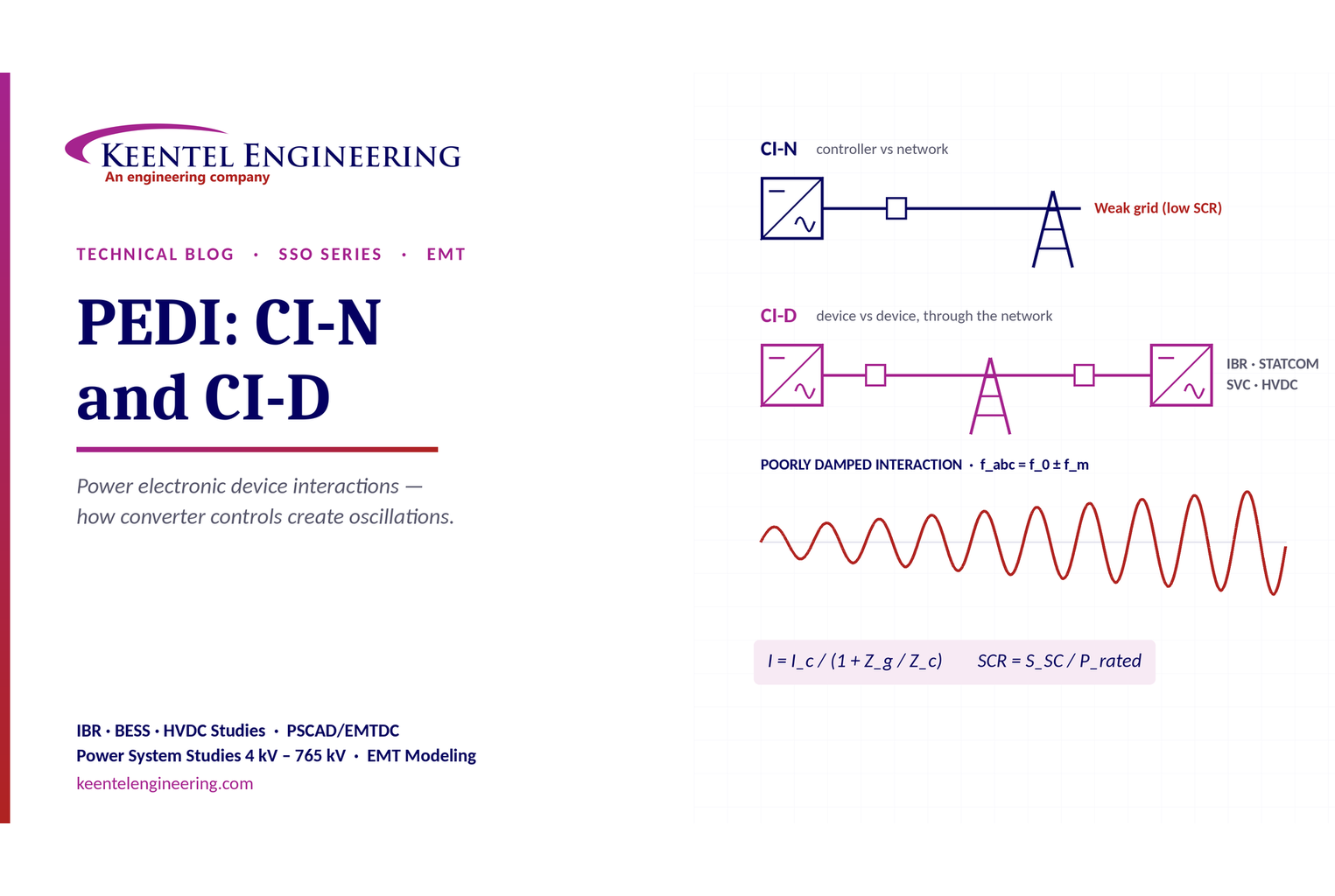
Learn power electronic device interactions (PEDI), including CI-N and CI-D, weak-grid stability, SCR, EMT studies, impedance analysis and mitigation for IBRs.
By SANDIP R PATEL
•
October 3, 2026
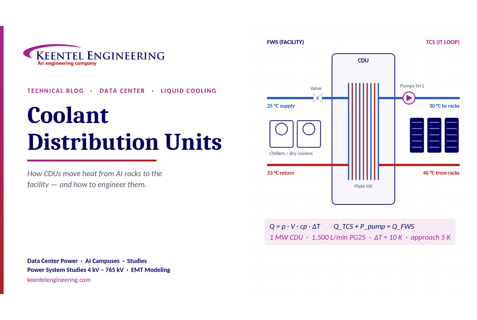
Learn how data center coolant distribution units (CDUs) work, including FWS and TCS loops, heat transfer, sizing, redundancy and liquid cooling for AI data centers.
By SANDIP R PATEL
•
October 3, 2026
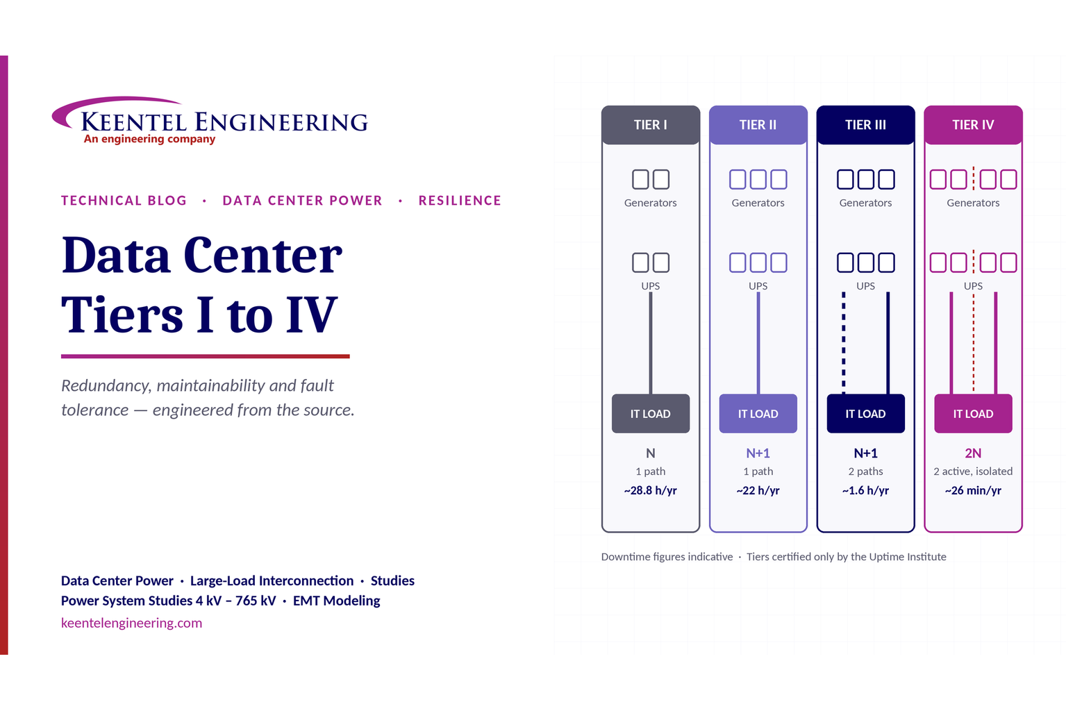
Compare Data Center Tiers I–IV, including redundancy, uptime, Tier III concurrent maintainability, Tier IV fault tolerance, UPS, generators and power design.

By SANDIP R PATEL
•
October 3, 2026
Learn how BESS supports grid stability through fast frequency response, voltage support, oscillation damping, black start, grid-forming controls and EMT studies.
By SANDIP R PATEL
•
October 3, 2026
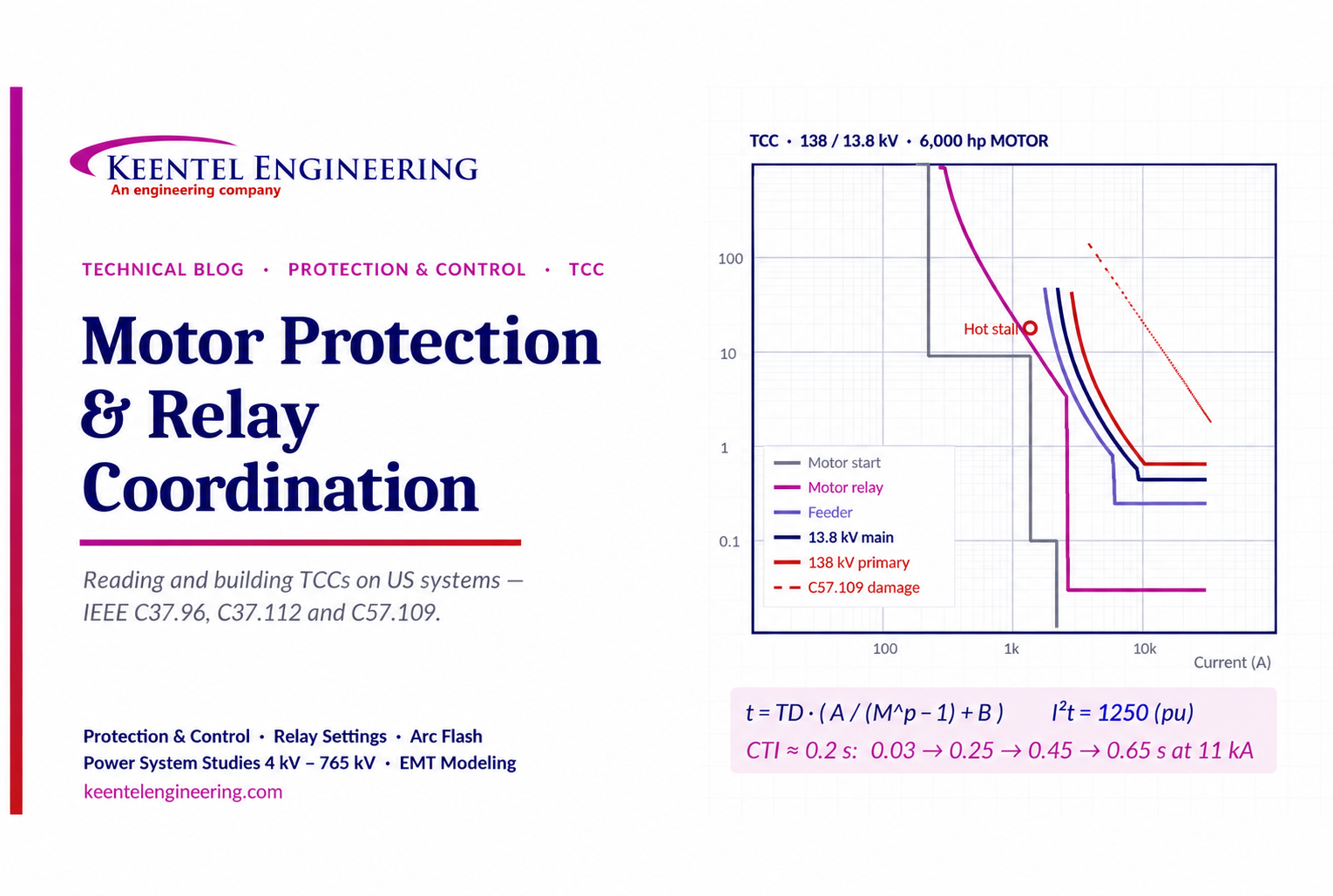
Learn motor protection and relay coordination using TCC curves, IEEE standards, transformer damage limits, CTI settings and a 138/13.8 kV example.





