Positive-sequence model development
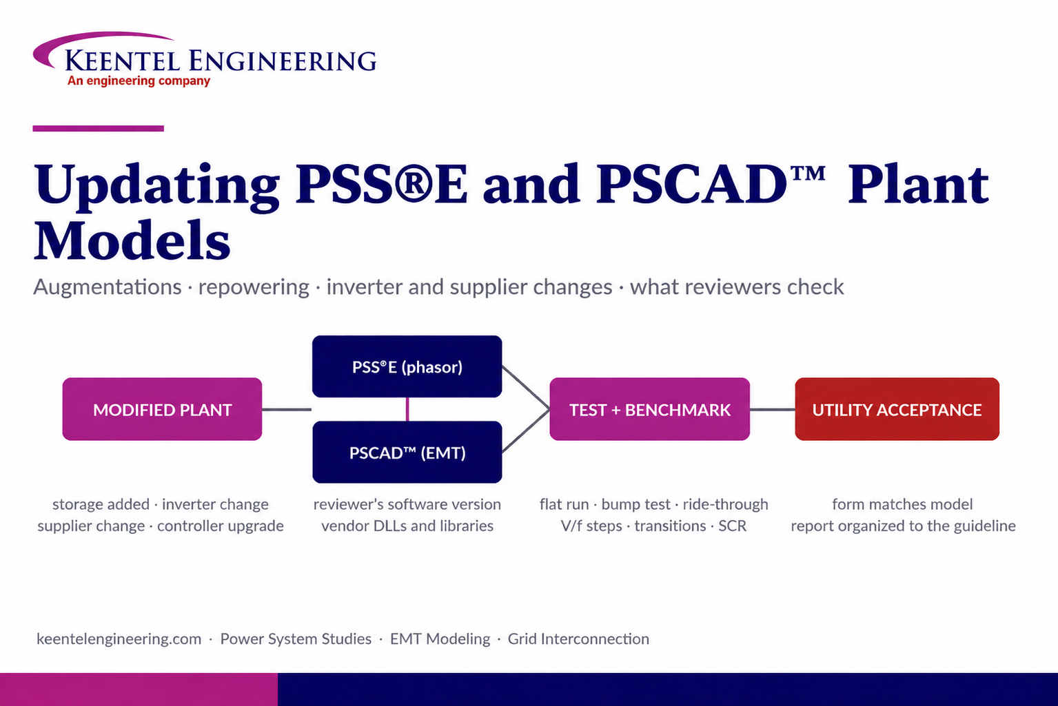
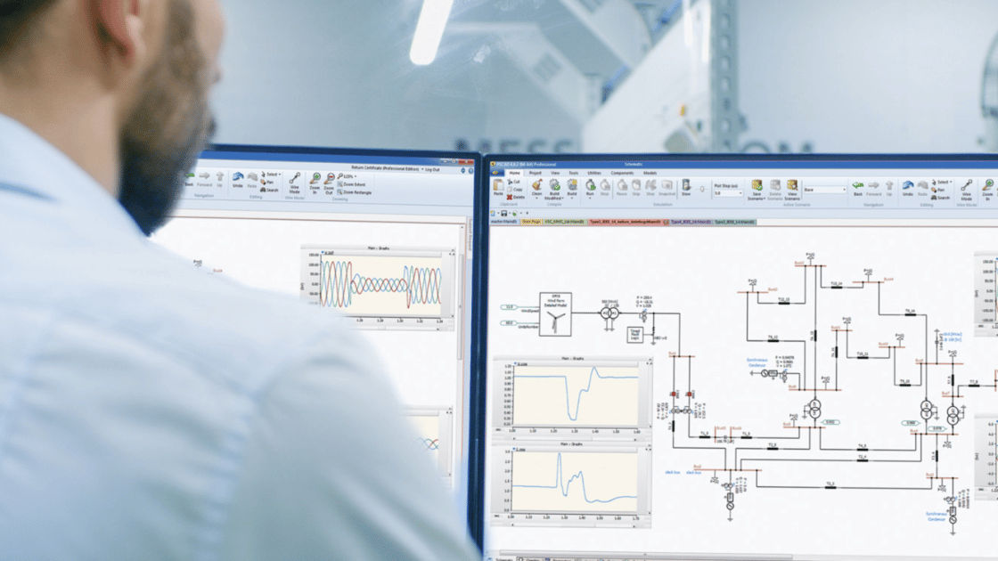
PSS®E and PSLF dynamic models using the appropriate generic or user-written models, parameterized from OEM data, plant-controller settings and the collector system.

Your Trusted Partner in Electrical Engineering and Power Systems
At Keentel Engineering, we deliver electrical power engineering services built on 30 years of experience and a commitment to excellence. Our clients include utilities, developers, EPCs, and public agencies across the U.S.
Unlike firms that sacrifice technical depth to chase billable hours, we prioritize precision, compliance, and value engineering. From transmission services and relay modeling to winterization and SCADA planning, we never compromise on quality.

At Keentel Engineering, we take pride in being the go-to electrical power engineering firm for power and utility system planning, substation design, protection, control, and power system analysis. The following attributes distinguish our team in utility-grade substation engineering and compliance-driven project delivery.
With three decades of hands-on project delivery, we bring unmatched expertise in substation layout design, substation electrical and civil engineering, relay protection, and grid-tie solutions. Our experience includes projects in complex terrain, urban retrofit environments, and utility-scale renewable integrations.
Our engineering process applies AutoCAD 3D, BIM modeling, and system-level substation design practices to ensure accurate planning, reduced errors, and efficient coordination across all project stakeholders.
Our workflow includes 3D substation design, enabling clash-free coordination between structural, electrical, and civil disciplines.
From grounding grid studies to relay protection settings, we engineer every detail to improve system reliability, performance, and operational safety. Our rigorous QA/QC process ensures compliance with IEEE, NFPA, and ISO/TSO interconnection standards.
Among leading electrical substation design companies, Keentel Engineering stands out for 30+ years of proven high-voltage and utility-grade project delivery.



First name, email and what you're interested in are all we need to get moving. Everything else, including drawings or an RFP, is optional.
A synchronous generator’s response to a fault is governed largely by physics. An inverter-based resource’s response is governed by code: phase-locked loops, current limits, momentary cessation logic, fault ride-through modes and plant-controller priorities. Change the firmware or a single parameter and the plant can behave very differently on the next disturbance.
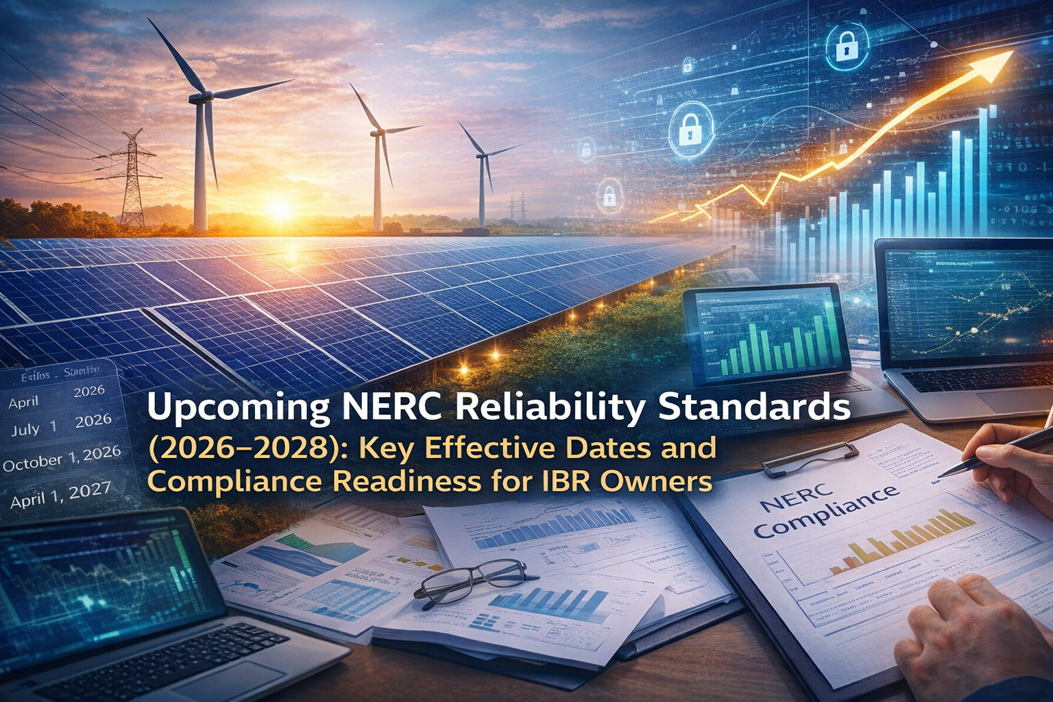
NERC disturbance reviews — including the Blue Cut Fire and Odessa events — documented solar and wind plants tripping or reducing output unexpectedly during normal grid faults, often in ways the submitted models did not predict. That experience drove NERC alerts on IBR performance and model quality, the Category 2 IBR registration initiative, and a set of new and revised standards directed by FERC Order No. 901.
The result is that model accuracy and ride-through capability are now tested from both sides: planners check whether your models are credible, and the standards check whether your plant actually stays connected and performs as modeled.
For an IBR, the model, the settings file and the ride-through evidence must describe the same plant. When any one of them is out of date, all three are.

Several of these standards are new or recently revised under FERC Order No. 901 and have phased implementation plans. Always confirm the version in effect and the effective dates that apply to your facility and registration.
| Standard / reference | What it addresses | Engineering evidence we produce |
|---|---|---|
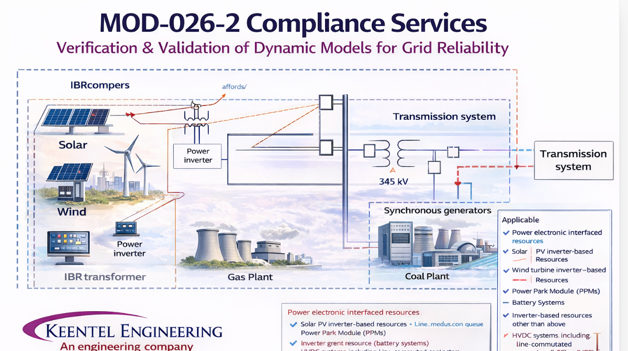
| MOD-026 / MOD-027 | Verification of plant volt/var and active power/frequency control models, being revised under Order No. 901 to better address IBRs | Model parameter review, test or disturbance data, simulated vs measured comparison, verification report |
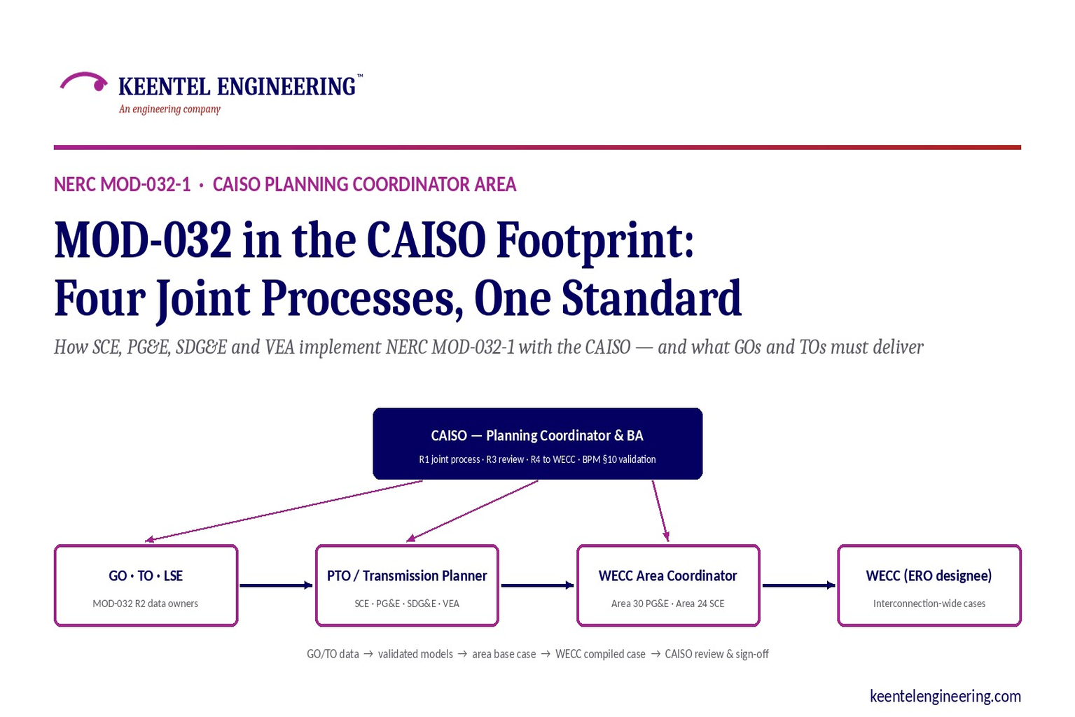
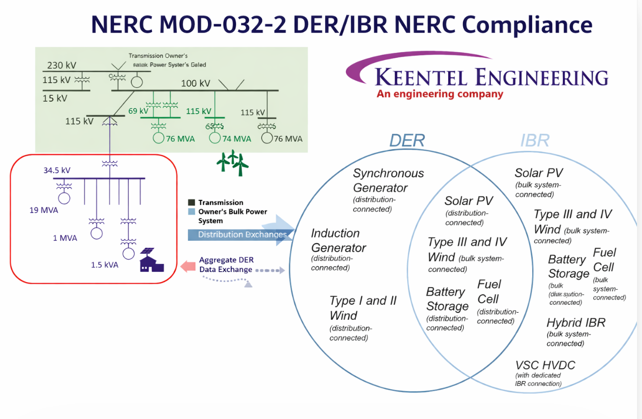
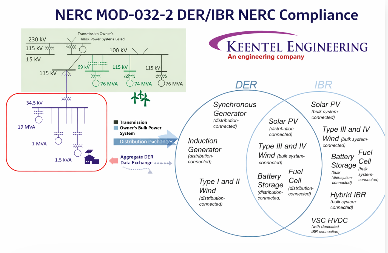
| MOD-032 | Modeling data provided to the Planning Coordinator and Transmission Planner | Positive-sequence dynamic, steady-state and short-circuit data; EMT models where the PC/TP requires them |
| MOD-025 | Real and reactive capability verification | Capability test plans and data review for inverter-based plants, including BESS charge and discharge |
| PRC-024 | Generator frequency and voltage protective relay settings — applicable to non-IBR generation as PRC-029 takes effect | Setting evaluation against the no-trip zones and documented equipment limitations |
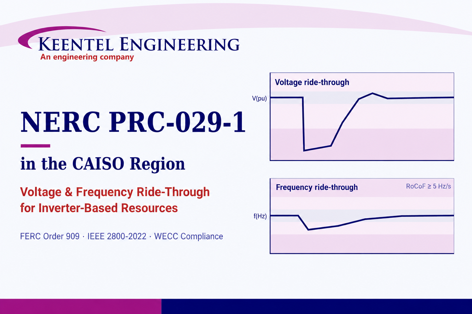
| PRC-029 | Frequency and voltage ride-through requirements for IBRs | Ride-through capability assessment, inverter and plant-controller settings review, EMT simulation, documentation for hardware-based exemptions for existing equipment where the standard allows |
| PRC-028 | Disturbance monitoring and recording for IBRs | Recording location and data-point review, trigger and retention settings, time-synchronization checks |
| PRC-030 | Identification, analysis and mitigation of unexpected IBR changes in output | Event detection process, root-cause analysis using plant and inverter records, corrective action plans |
| IEEE 2800-2022 | Interconnection and interoperability performance for IBRs connected to transmission — not a NERC standard | Gap review against the IEEE 2800 requirements your TO or ISO/RTO has adopted |
PSS®E and PSLF dynamic models using the appropriate generic or user-written models, parameterized from OEM data, plant-controller settings and the collector system.
PSCAD™ plant models built from vendor-specific inverter models, with the actual firmware version, protection settings and power plant controller represented.
Side-by-side comparison of positive-sequence and EMT response across faults, voltage and frequency steps and weak-grid cases, with differences explained.
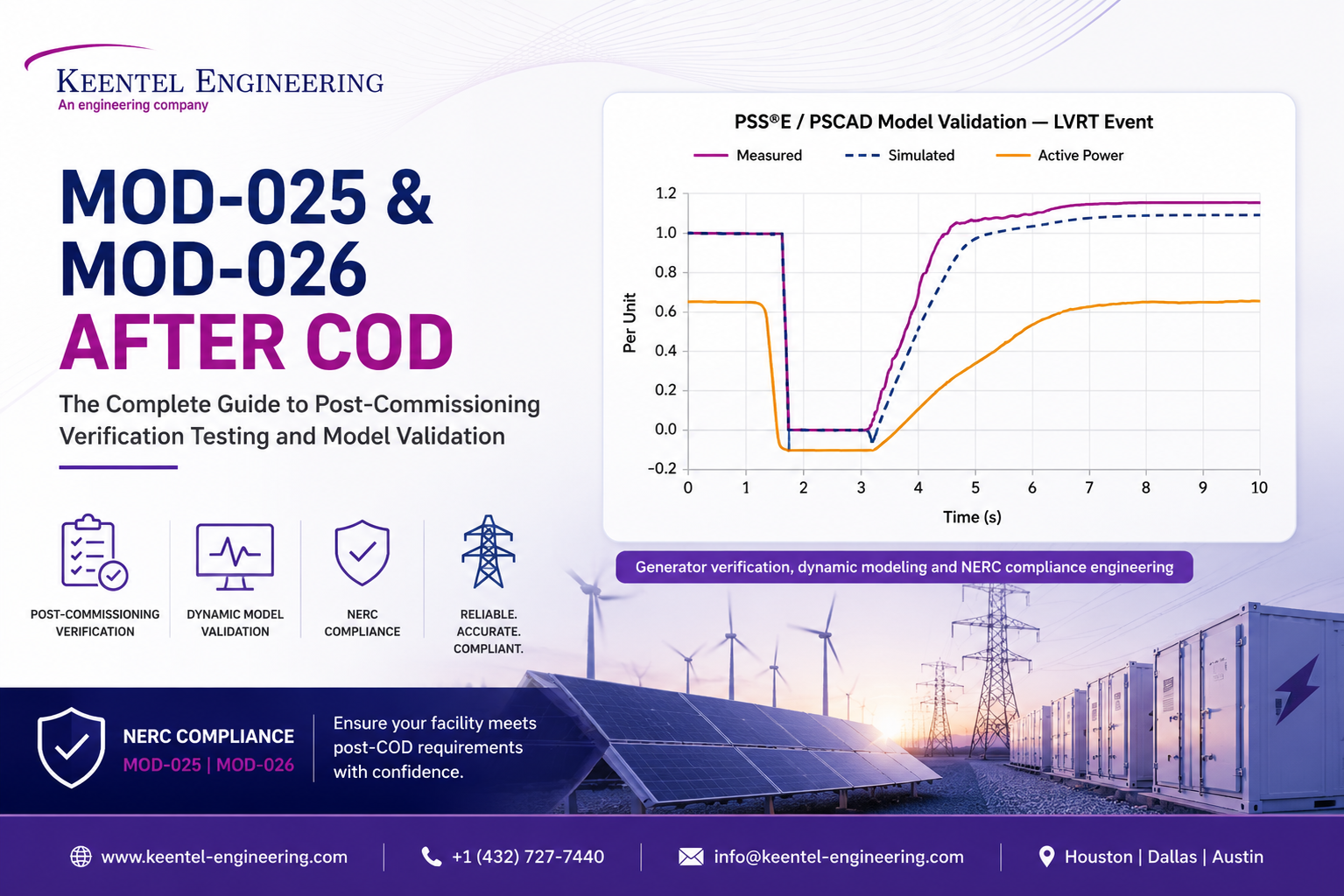
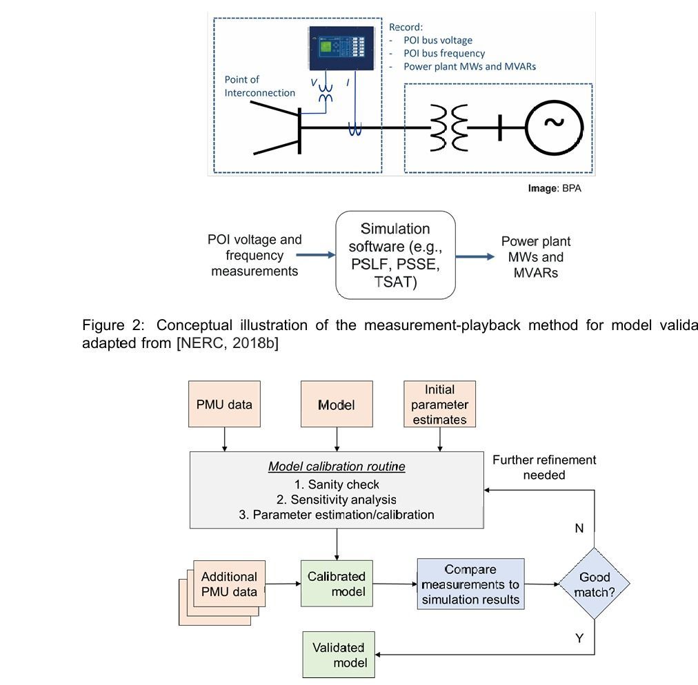
Comparison of simulated response to staged tests, commissioning records or recorded disturbances, with tuning limited to physically justified parameters.
Evaluation of inverter, plant-controller and protective-relay settings against the voltage and frequency ride-through requirements, supported by EMT simulation.
Technical records for existing equipment with hardware-based ride-through limitations, prepared to the documentation and timing requirements the standard defines.
Disturbance-monitoring design review, event detection criteria, root-cause analysis and corrective action plans for unexpected output changes.
Model, settings and ride-through updates after firmware upgrades, inverter replacement, controller retuning, augmentation or conversion to a hybrid plant.
Planning Coordinators and Transmission Planners increasingly ask for both a positive-sequence model for regional planning cases and an EMT model for detailed studies of fast controls, weak-grid conditions and ride-through behavior. The two must tell the same story about the plant.
Used in interconnection studies, annual planning cases and MOD-032 submissions. We select the approved model structure for the technology, map OEM parameters to it, and represent the collector system, main power transformer and plant controller at the level the recipient requires.
Built from the OEM’s vendor-specific model with the firmware version installed at site. We check model usability — initialization, time step, documentation and accuracy — against the recipient’s EMT model requirements before any study is run.
PRC-029 establishes frequency and voltage ride-through requirements specific to inverter-based resources, and as it takes effect IBRs move out of PRC-024, which continues to apply to synchronous and other non-IBR generation. Unlike a relay-setting standard, PRC-029 looks at whether the plant as a whole — inverters, plant controller, auxiliary systems and protective relays — rides through the defined voltage and frequency conditions.
For existing plants, some inverter hardware cannot meet every ride-through requirement regardless of settings. The standard provides a path to document hardware-based limitations for equipment already in service; that documentation has defined content and deadlines, so confirm them in the version in effect and start early.
Collect inverter, plant-controller and relay settings — including those held only by the OEM
Compare every trip and momentary-cessation setting with the ride-through requirements
Simulate ride-through performance in PSCAD™ where settings alone do not answer the question
Identify settings changes versus true hardware limitations
Prepare exemption documentation for qualifying existing equipment
Coordinate settings changes with the OEM, the plant owner and the Transmission Owner
IEEE 2800-2022 defines performance requirements for IBRs interconnecting to transmission and sub-transmission systems. It is not a NERC standard, but several ISOs/RTOs and Transmission Owners have adopted it in whole or in part in their interconnection requirements. We review plant capability and settings against the specific clauses your interconnecting utility has adopted.
NERC has issued alerts to IBR owners and operators on performance issues and model quality, asking for specific actions on settings, models and data. Model problems ERO reviews have highlighted include generic models that do not match installed equipment, models not updated after commissioning, and EMT models that are unusable or inconsistent with positive-sequence models.
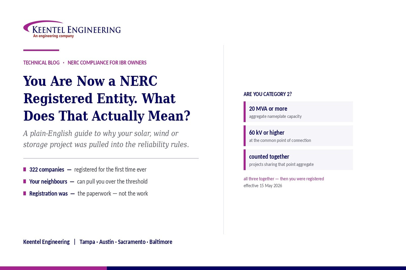
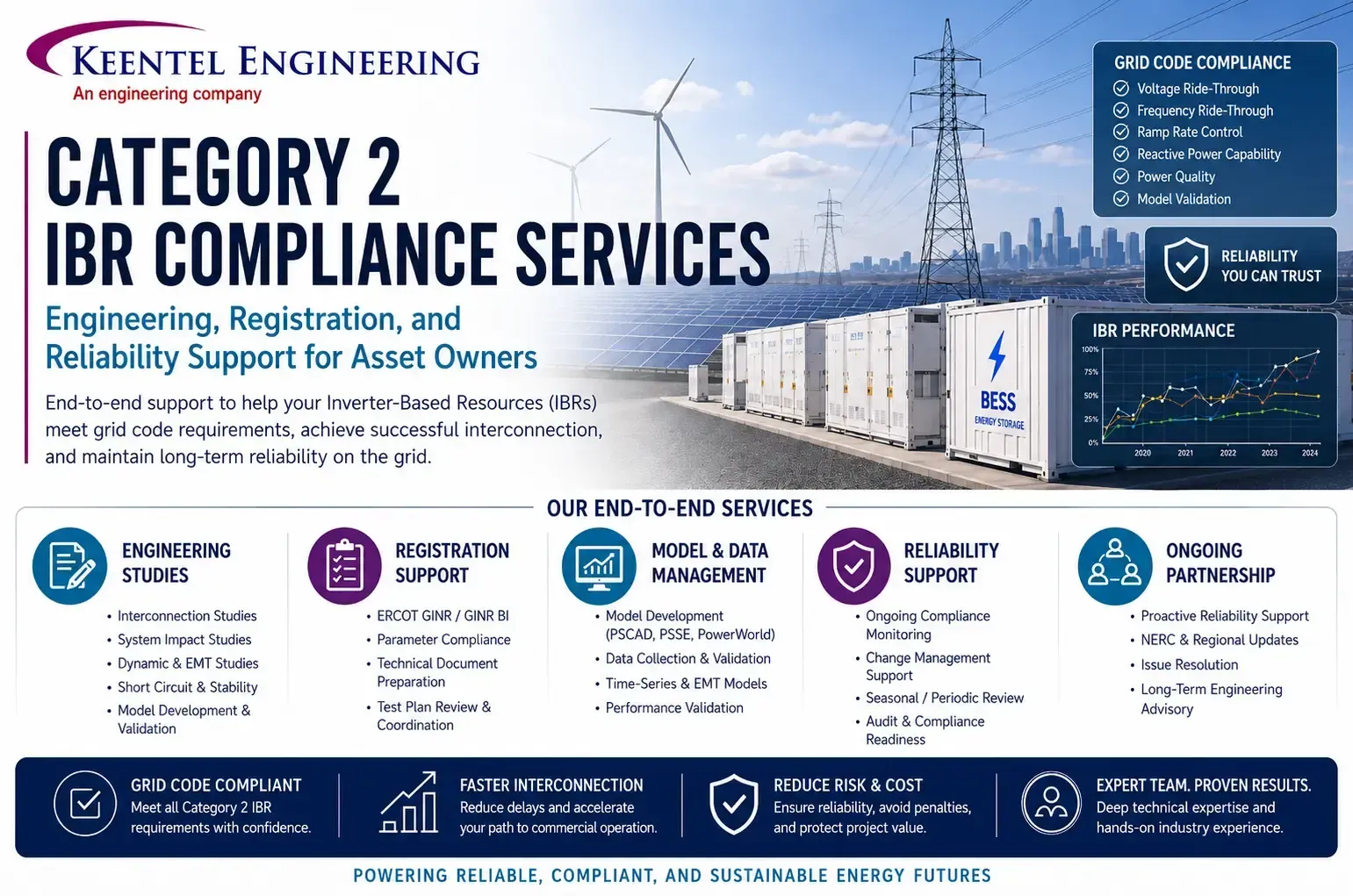
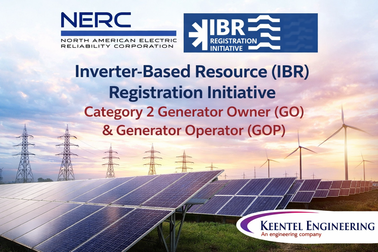
NERC’s registration criteria now include Category 2 Generator Owners and Generator Operators for non-BES inverter-based resources with 20 MVA or more of aggregate nameplate capacity connected at 60 kV or higher. Newly registered owners inherit modeling, ride-through and disturbance-monitoring obligations, often for plants whose models and settings were never assembled for compliance purposes.
OEM models, firmware versions, inverter and plant-controller settings files, relay settings, one-lines, collector data and PC/TP model requirements.
Check that the models and settings reflect the equipment and firmware actually in service, not the design submittal.
Develop or update PSS®E, PSLF and PSCAD™ models and benchmark them against each other.
Compare model response with test, commissioning or disturbance data and tune within justified bounds.
Assess PRC-029 or PRC-024 performance, PRC-028 recording and PRC-030 event processes; identify settings changes and exemption candidates.
Issue model packages, validation and ride-through reports, and a change trigger list so the next firmware update prompts re-validation.
| Deliverable | Purpose |
|---|---|
| Positive-sequence model package (PSS®E / PSLF) | Dynamic, steady-state and short-circuit data with parameter documentation |
| EMT model package (PSCAD™) | Vendor-specific plant model with usability checks and study-ready documentation |
| Model benchmarking report | Positive-sequence vs EMT comparison with differences explained |
| Model validation report | Simulated vs measured response supporting MOD-026 / MOD-027 verification |
| PRC-029 ride-through assessment | Settings review, simulation results, compliance conclusions and recommended changes |
| Hardware limitation / exemption documentation | Technical basis for qualifying existing equipment, prepared to the standard’s requirements |
| PRC-028 / PRC-030 evidence | Monitoring design review, event detection criteria, event analyses and corrective action plans |
| Re-validation trigger list | The firmware, settings and equipment changes that should prompt a model and ride-through update |
| Gap | Why it matters |
|---|---|
| Models reflect the design submittal, not the installed firmware | Firmware and controller changes after commissioning can alter fault response and ride-through behavior. |
| EMT model will not initialize or run at the required time step | Planning entities reject unusable EMT models, delaying studies and submissions. |
| Positive-sequence and EMT responses disagree | Unexplained differences undermine confidence in both models. |
| Inverter trip settings unavailable to the owner | Ride-through compliance cannot be demonstrated without the settings that govern tripping. |
| Augmentation not reflected in models | Added BESS, replaced inverters or hybrid conversion change plant behavior and capability. |
| No process to detect unexpected output changes | PRC-030 requires owners to identify and analyze qualifying events, not just react to utility inquiries. |
We build and run PSS®E, PSLF and PSCAD™ IBR models ourselves — the same models used in interconnection studies.
Relay, inverter and plant-controller settings are reviewed as one system, the way a disturbance tests them.
Former NERC audit-team leadership and subject-matter experts know what reviewers ask for when IBR evidence is examined.
Model submissions and interconnection requirements across ERCOT, CAISO, PJM, MISO, SPP and WECC, with support in all six Regional Entities.



Send us your OEM models, settings files and latest submissions. Keentel will show you where your models, ride-through settings and monitoring fall short — and build the evidence to close the gap before your planner or auditor finds it.
Serving utilities, EPCs, developers, and infrastructure organizations supporting critical power systems nationwide.