
A Coordinated Electric System Interconnection Review—the utility’s deep-dive on technical and cost impacts of your project.
Challenge: Frequent false tripping using conventional electromechanical relays
Solution: SEL-487E integration with multi-terminal differential protection and dynamic inrush restraint
Result: 90% reduction in false trips, saving over $250,000 in downtime
The three operating regions you have to design to
| Device | Output vs voltage | Response | Best suited to | Main limitations |
|---|---|---|---|---|
| Mechanically switched capacitor or reactor | Proportional to voltage squared | Seconds; discrete steps; limited switching operations per day | Steady-state reactive supply, voltage profile, loss reduction | No dynamic capability; step voltage change on switching; capability collapses when most needed |
| Static var compensator | Capacitive branches proportional to voltage squared | A few cycles; continuously controllable | Continuous control where cost matters and deep voltage support is not the driver | Square-law capability loss; harmonic filters are part of the plant and interact with the network |
| STATCOM | Approximately proportional to voltage — constant current capability | One to two cycles closed loop; converter response faster still | Voltage stability margin, weak interconnections, fast disturbance recovery, flicker and unbalance compensation | Higher capital cost; converter losses; adds a converter and its control dynamics to the network |
| Synchronous condenser | Governed by machine capability and excitation | Excitation response in the hundreds of milliseconds; inherent inertial response instantaneous | System strength and inertia, short-circuit contribution, black start support | Rotating plant with maintenance and losses; slower controlled response than a converter |
| STATCOM with energy storage | Reactive as a STATCOM, plus real power within the storage rating | As STATCOM for reactive; real power limited by storage | Where a real power deficiency is part of the problem | Cost and complexity of the storage; different failure and maintenance profile |
MOD-032 in the CAISO Footprint: Four Joint Processes, One Standard
September 6, 2026 | Blog
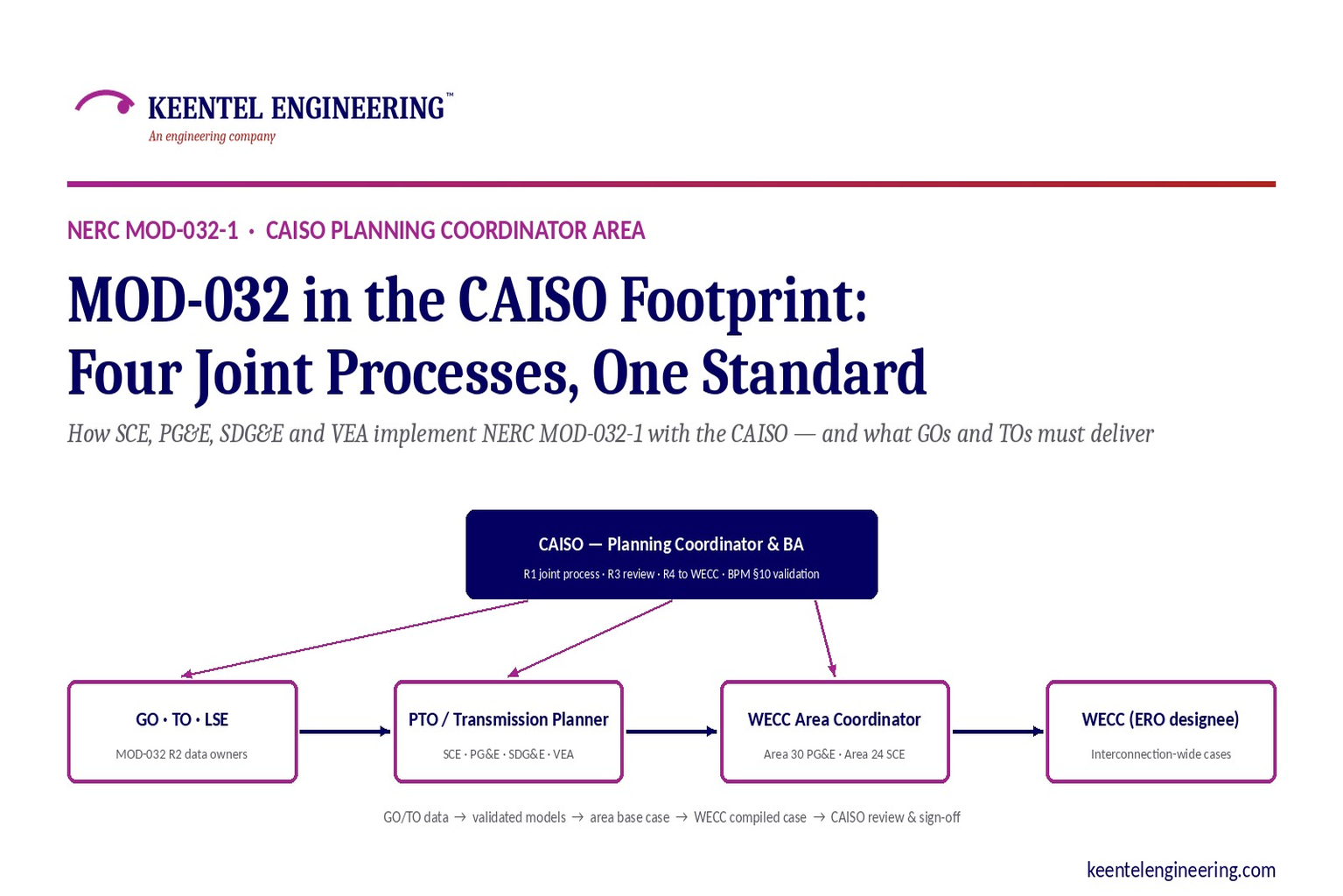
How Southern California Edison, Pacific Gas and Electric, San Diego Gas & Electric, and Valley Electric Association implement NERC Reliability Standard MOD-032-1 with the California ISO — what is common, what differs, and what Generator Owners and Transmission Owners must deliver, when, in what format, and to whom
Executive Summary
NERC Reliability Standard MOD-032-1, Data for Power System Modeling and Analysis, is short: four requirements and a one-page attachment. Its purpose is to make sure that every steady-state, dynamics, and short-circuit model used to plan the bulk power system is built from data that the owners of the equipment actually supplied, in a format the planners can use, on a schedule that keeps the interconnection-wide cases current. The standard does not say what the data must look like. It delegates that to each Planning Coordinator and its Transmission Planners, who must jointly write the data requirements and reporting procedures for their planning area and post them where the data owners can find them.
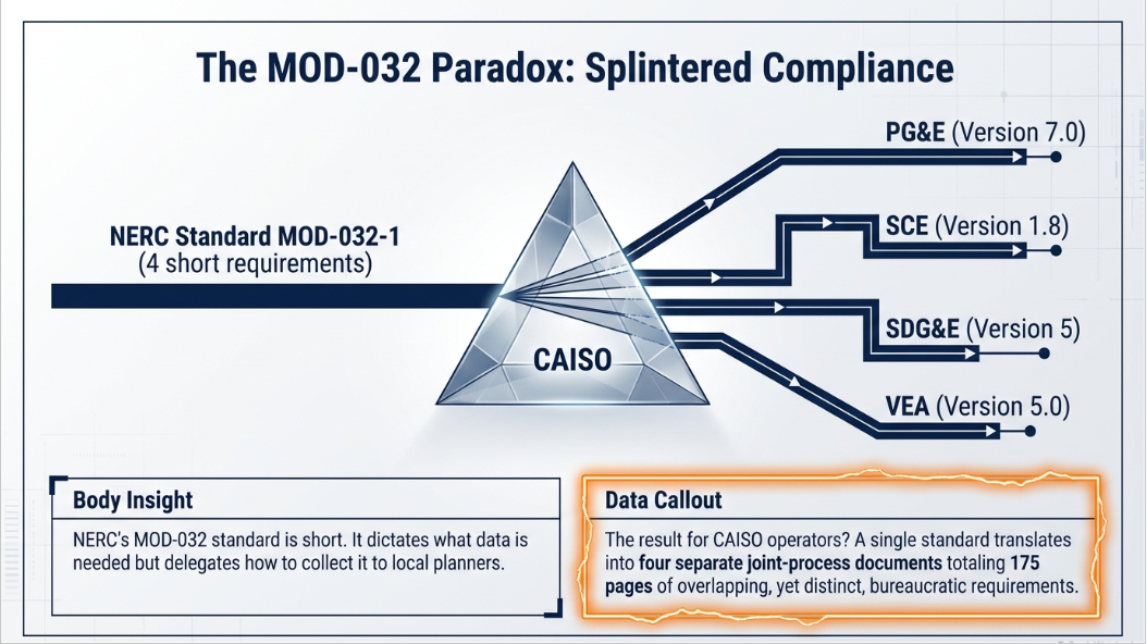
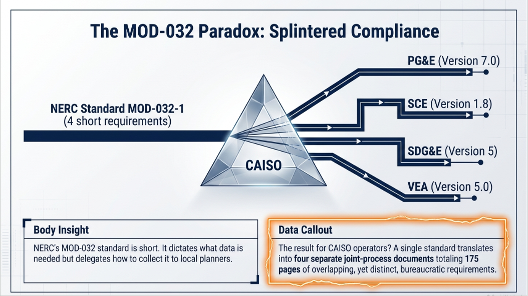
In the California ISO footprint, the CAISO is the Planning Coordinator and Balancing Authority, and each Participating Transmission Owner is a Transmission Planner for its own system. The result is not one CAISO MOD-032 document but a family of joint process documents, one for each PTO. This guide examines the four that govern the largest share of generation and transmission in the CAISO area: the CAISO–SCE process (Version 1.8, December 2024), the CAISO–PG&E process (Version 7.0, July 2024), the CAISO–VEA process (Version 5.0, effective November 2025), and the CAISO–SDG&E process (Version 5, July 2026). Together they run to roughly 175 pages, and a Generator Owner with plants in more than one service territory, or a Transmission Owner interconnecting across a PTO boundary, must satisfy each of them.
The four documents share a common skeleton. All rely on the WECC Data Preparation Manual for the modeling rules themselves. All require data in GE PSLF format, apply the same 10 MVA individual and 20 MVA aggregate modeling thresholds, require steady-state and dynamic data to agree, and populate the CAISO market resource ID in the generator Long ID field. All incorporate the CAISO Transmission Planning Process Business Practice Manual Section 10 generator data review, under which the CAISO validates each generator's package, issues a compliance letter, and hands the validated data to the PTO within 60 days so it can be submitted to WECC in the next base case request. All repeat the 13-calendar-month submission ceiling, the written-confirmation shortcut for unchanged data, the CAISO Tariff Section 25.5 notice of 90 days before modifying a generating facility, the FAC-014-3 Requirement R6 tie between planning ratings and operating ratings, the CAISO sign-off sheet for WECC base case review, and four-year evidence retention.
The differences are in the details that determine whether a submission is accepted or bounced. The four PTOs sit in three different WECC areas with two different Area Coordinators. Their annual data deadlines fall in different months: November 15 for PG&E, February for VEA, and the end of the calendar year for SCE and SDG&E. Short-circuit data is required in ASPEN format by PG&E, is not part of the routine submittal at VEA and SDG&E, and is accepted in ASPEN or CAPE by SCE when it is not native to PSLF. The criteria for modeling a future generator range from "in construction" at PG&E to "executed interconnection agreement" at VEA to SDG&E's explicit statement that an executed GIA alone is not sufficient. Each PTO has its own base case architecture, its own internal source documents for ratings and voltage criteria, its own bus and zone ranges, and its own review checklist.
This guide walks through the standard, the CAISO structure, the common core, the differences, the end-to-end obligations of a Generator Owner and of a Transmission Owner, the WECC base case cycle and Anchor Data Set, the traps and internal inconsistencies we found in the documents, and closes with how Keentel Engineering supports Generator Owners and Transmission Owners through the MOD-032 and BPM Section 10 process, followed by a 25-question FAQ.
Who this guide is for
Generator Owners with plants in the SCE, PG&E, SDG&E, or VEA service territories, including utility-scale solar, wind, storage, and hybrid projects approaching commercial operation; developers preparing the model packages required at interconnection; Transmission Owners, municipal utilities, and merchant transmission companies that provide data to a PTO or to the CAISO; and compliance staff who must produce MOD-032 evidence at audit.
1. MOD-032-1 in Brief: What the Standard Requires
MOD-032-1 has four requirements. Requirement R1 obliges each Planning Coordinator and each of its Transmission Planners to jointly develop steady-state, dynamics, and short-circuit modeling data requirements and reporting procedures for the PC's planning area. The procedures must cover the data listed in Attachment 1, specify the data format, the level of detail to which equipment is modeled, the case types or scenarios to be modeled, and a schedule for submission of data at least once every 13 calendar months, and they must be distributed or posted so that the entities responsible for providing the data can find them. The four CAISO joint process documents are the R1 deliverable.
Requirement R2 turns the obligation around. Each Balancing Authority, Generator Owner, Load Serving Entity, Resource Planner, Transmission Owner, and Transmission Service Provider must provide steady-state, dynamics, and short-circuit modeling data to its Transmission Planner and Planning Coordinator according to the R1 procedures. Requirement R3 governs disputes: when the PC or TP gives written notice of a technical concern with submitted data, including the technical basis for the concern, the data owner must respond within 90 calendar days with either corrected data or a technical justification for keeping the existing data. Requirement R4 requires the PC, or its designee, to make models for its planning area available to the Electric Reliability Organization or its designee to support creation of the interconnection-wide cases. In the Western Interconnection that designee is WECC, and the models are delivered through WECC's annual base case compilation.
Attachment 1 is the minimum data list, organized in three columns and tagged with the functional entity responsible for each item. The steady-state column covers buses (TO), aggregate demand (LSE), generating units including real and reactive capability, station service, regulated bus and voltage set point, machine MVA base, step-up transformer, and type (GO, and RP for future planned resources), AC lines (TO), DC systems (TO), transformers including tap data (TO), shunt reactive compensation (TO), and static VAR systems (TO). The dynamics column covers generator, excitation system, governor, and power system stabilizer models (GO/RP), demand (LSE), wind turbine and photovoltaic data (GO), SVS and FACTS (GO/TO/LSE), and DC system models (TO); where a user-written model is substituted for a library model, block diagrams, parameter names and values, and a list of state variables must accompany it. The short-circuit column requires positive, negative, and zero sequence data for every applicable steady-state element (GO/RP/TO) and mutual line impedance data (TO). Every column ends with "other information requested by the PC or TP necessary for modeling purposes," which is the hook that lets a PC ask for more than the minimum.
| Requirement | Who | What | Time element |
|---|---|---|---|
| R1 | PC and its TPs, jointly | Data requirements and reporting procedures covering Attachment 1, format, level of detail, scenarios, submission schedule; posted or distributed | Schedule must call for submission at least every 13 calendar months |
| R2 | BA, GO, LSE, RP, TO, TSP | Provide steady-state, dynamics, and short-circuit data per the R1 procedures | Per the R1 schedule |
| R3 | Any R2 entity notified in writing | Respond with corrected data or a technical basis for keeping the data | 90 calendar days, unless the PC/TP agrees to longer |
| R4 | PC or designee | Make planning-area models available to the ERO designee (WECC) for interconnection-wide cases | Per the WECC base case compilation schedule |
Two features of the standard shape everything that follows. First, MOD-032 is a
data-delivery standard, not a model-quality standard. Whether a generator's dynamic model actually matches the machine is the province of MOD-026 and MOD-027, whether its real and reactive capability has been verified is MOD-025, and whether its protection settings coordinate with ride-through is PRC-019, PRC-024, and now PRC-029. But because the CAISO joint processes fold the BPM Section 10 validation into the MOD-032 data path, a Generator Owner in California cannot in practice satisfy MOD-032 without a package that also satisfies those model-quality standards. Second, the standard names WECC's interconnection-wide process as the target. The WECC Data Preparation Manual, the Master Dynamics File, the approved dynamic model library, the Area Coordinator structure, and the annual compilation of roughly eleven base cases are therefore incorporated by reference into every CAISO document.
2. How the CAISO Organizes MOD-032: One Planning Coordinator, Four Joint Processes
The CAISO is the registered Planning Coordinator and Balancing Authority for the CAISO Balancing Authority Area. Each Participating Transmission Owner, defined as a Transmission Owner that has placed its facilities under CAISO operational control through a Transmission Control Agreement, acts as Transmission Planner for its own system. Rather than issuing a single PC-wide document, the CAISO has executed a separate joint process with each PTO, and each joint process also covers the non-PTO entities embedded in that PTO's WECC area. The four documents reviewed here are signed by the CAISO's Regional Transmission managers for the north and south and by the corresponding PTO planning managers, and each carries its own version history back to 2015, when MOD-032-1 became enforceable.
| Joint process | Version / date | WECC area and bus numbering | Area Coordinator | Other entities covered |
|---|---|---|---|---|
| CAISO – SCE | Version 1.8, December 9, 2024 (70 pp.) | Area 24 "So Calif"; SCE buses 24000–24999, 240000–249999, 94000–95999, 29000–29999, 290000–299999; zones 240–259, 2400–2599, 940–959, 290–299, 9400–9599 | SCE (Southern California Area Coordinator) | MWD, VEA, GridLiance West, CDWR, and the cities of Anaheim, Azusa, Banning, Colton, Pasadena, Riverside, Vernon |
| CAISO – PG&E | Version 7.0, July 30, 2024 (39 pp.) | Area 30; internal areas 1–51 for non-full-loop cases, all converted to Area 30 for full-loop cases; zones 300–405 | PG&E (Area Coordinator for Area 30) | Trans Bay Cable, WAPA (Path 15 participation), Hetch Hetchy/CCSF, CDWR, Silicon Valley Power, and the northern municipal utilities |
| CAISO – VEA | Version 5.0, effective November 3, 2025 (25 pp.) | Zone 890 within Area 24; VEA/GLW buses 18900–18999, 189000–189999 | SCE (VEA submits to SCE, copies the CAISO) | GridLiance West as a TO in VEA's territory; LSEs and Participating Generator Owners in the VEA area |
| CAISO – SDG&E | Version 5, July 2026 (43 pp.) | Area 22 | Southern California Area Coordinator (SDG&E submits to it and sends WECC upload screenshots to the CAISO) | Generator Owners in SDG&E's service area; merchant substation resources coordinated with SCE |
The geography matters for a data owner because it determines
where the data goes and who compiles it. PG&E is its own Area Coordinator, so a PG&E-area Generator Owner's data travels GO → PG&E → WECC, with the CAISO copied and reviewing. SCE is the Southern California Area Coordinator, so an SCE-area GO's data travels GO → SCE → WECC. A VEA-area GO sends data to VEA, VEA submits to SCE, and SCE submits to WECC, so there are two Transmission Planner hand-offs before the data reaches the interconnection-wide case. SDG&E compiles its own Area 22 case and hands it to the Southern California Area Coordinator, and documents each upload to the CAISO with a screenshot. In every path the CAISO, as PC, reviews the area case during the WECC review window and issues comments on a standard sign-off sheet that the PTO must answer in writing.
Practice note: the CAISO email addresses are the same everywhere; the PTO addresses are not
The CAISO Planning Coordinator inbox for MOD-032 submittals is GridModelingData@caiso.com in all four documents. The Transmission Planner inboxes differ: basecase@sce.com for SCE, GenModel@pge.com for PG&E, VEAengineering@vea.coop for VEA, and basecase@semprautilities.com for SDG&E. PG&E additionally specifies the email subject line "MOD-032-1: Modelling data submittal under Requirement R2". A submission to the wrong inbox is not a submission, and Keentel has seen Generator Owners lose a full cycle because a package went only to the CAISO or only to the PTO.
3. What Is Common to All Four Processes
Underneath the different page counts and organizational styles, the four documents implement the same architecture. A Generator Owner or Transmission Owner that understands the common core has understood roughly three-quarters of every document.
3.1 The WECC Data Preparation Manual governs the modeling rules
Every joint process points to the latest approved WECC Data Preparation Manual as the source of the detailed modeling requirements, and every one says that where the process document and the DPM conflict, the DPM controls, with a short list of local exceptions. SCE reproduces the DPM data tables in its Appendix A; PG&E attaches the DPM as its Appendix B and lists exceptions; VEA and SDG&E incorporate it by reference. The DPM sections a data owner will actually use are the bus, generator, AC line, transformer, fixed and controlled shunt, load, DC line, and substation tables, the dynamic modeling procedure, and the contingency and Remedial Action Scheme file format.
3.2 GE PSLF is the format of record
All four require steady-state data in PSLF .epc or .sav and dynamics in PSLF .dyd. SDG&E accepts a text file where a submitter has no PSLF license, and PG&E notes that non-licensees may obtain the PSLF model documentation from the vendor under a non-disclosure agreement. In practice a Generator Owner's package is expected to initialize cleanly in PSLF, and the BPM Section 10 acceptance test requires screenshots proving the .epc and .dyd files initialize with a real and reactive power spread of less than 1 MW/MVAr or 1 percent over a ten-second no-disturbance run. PowerWorld and PSS/E models are useful for the owner's own studies but do not satisfy the CAISO submittal.
3.3 The 10 MVA / 20 MVA / 60 kV modeling thresholds and the collector-based exception
The DPM rule, restated in each document, is that an individual generating unit of 10 MVA or larger connected at 60 kV or higher must have its own steady-state and dynamic model; an aggregate of 20 MVA or larger at 60 kV or higher must be modeled by unit unless it is a collector-based facility, in which case wind, solar, and storage plants may be represented as a single-unit or multiple-unit equivalent generator behind an equivalent pad-mount transformer, an equivalent collector system, and the main step-up transformer, following the WECC wind and PV power plant modeling guides. Facilities below 10 MVA, or connected below 60 kV, may be modeled explicitly or aggregated. Utility-scale DER of 10 MVA or larger is modeled explicitly on the low side of its transformer with a dynamic model; smaller U-DER and all retail-scale DER go into the distributed-generation fields of the composite load model. Retired units may be deleted or have their unit ID changed to "R*".
3.4 Steady-state and dynamic data must agree
Bus number, bus name, unit ID, bus voltage, and machine MVA base must be identical between the power flow and the dynamics record. Pmax in the power flow may not exceed the governor model's capability. The sub-transient reactance in the power flow record must match the machine model. The base-load flag must be consistent. Generator step-up transformers are modeled explicitly, never through the internal GSU fields of the generator record. Station service of 1 MW or more is an explicit load with ID "SS". These consistency rules are the most frequent source of review comments.
3.5 The CAISO market resource ID in the Long ID field
A requirement added to all four documents in 2023–2024 is that the CAISO market resource identifier for every Participating Generator be populated in the PSLF generator Long ID field and maintained by the PTO in coordination with the CAISO. This ties the planning model to the market model and to the CAISO's Section 10 category and phase tracking, and it is now a checklist item in every review.
3.6 The BPM Section 10 generator data review is the front door
Since 2019 the CAISO and the PTOs have operated a joint generator data review that implements Section 10 of the CAISO Transmission Planning Process BPM. A Generator Owner submits its data template and supporting package to the CAISO; the CAISO validates it and issues a compliance letter; within 60 calendar days of that letter the CAISO posts the complete validated package to a per-generator folder on the Market Participant Portal and notifies the PTO; the PTO then submits the validated PSLF data to WECC in response to the next WECC base case data request letter (or the second one, if the first is due within 60 days); and both the CAISO and the PTO check during WECC review that the validated data actually made it into the compiled case and the Master Dynamics File. The validated package is the same in all four documents: equipment data including short-circuit data, the steady-state model in .epc, the dynamic model in .dyd, a single-line diagram, the real and reactive capability test report, the dynamic model validation test report, and an electromagnetic transient model where sub-synchronous resonance or other EMT studies apply.
All four documents also carry the same EMT exception: if the only element of the package that has not been received or validated is the EMT model, the PTO proceeds to submit the validated PSLF power flow and dynamic data to WECC rather than hold the whole package. SCE's version is slightly narrower in that SCE updates the master base case with the validated power flow data in that circumstance.
3.7 The 13-month clock, the unchanged-data confirmation, and the 90-day tariff notice
Every document restates the R1.2.4 rule that data be submitted at least once every 13 calendar months, and three of them (SCE, PG&E, SDG&E) translate it as "by the end of each calendar year, but not to exceed 13 months between submissions." All four accept a written confirmation that nothing has changed in place of a re-submission. All four remind Generator Owners that CAISO Tariff Section 25.5 requires notice to the CAISO and the PTO at least 90 calendar days before modifying a generating facility, which routes through the Generator Management BPM's material modification process and, where the change alters the model, back into Section 10.
3.8 FAC-014-3 Requirement R6: planning ratings must match operating ratings
Each document was amended in 2024 to state that the facility ratings, including their applicable time durations, that a Transmission Owner provides for planning models and the CAISO Transmission Register must be consistent with the ratings it provides to its Transmission Operator and RC West under the RC's System Operating Limit methodology and the CAISO Planning Standards, unless a technical rationale is provided. For a Transmission Owner this means that a rating change made for operations must flow into the planning submittal in the same cycle, and that the eight seasonal normal and emergency ratings in the model must be traceable to the same source as the operating ratings.
3.9 CAISO review, the sign-off sheet, and four-year evidence retention
During each WECC base case review window the CAISO reviews the PTO's area data and returns a case review sign-off sheet, a table of numbered deficiencies with recommended changes and a column for the PTO's response. The PTO must respond in writing, either confirming the change or explaining with a technical basis why the data stands, which is the R3 mechanism applied at the PTO level. The sheet flows PTO → Area Coordinator → WECC. All four documents commit the parties to retain compliance evidence for at least four years: the joint process itself and its posting, data request letters, correspondence establishing each entity's system representation, WECC submittal confirmations, review comments and responses, and signed checklists.
3.10 The CAISO review checklist, DER modeling, and the Anchor Data Set
VEA and SDG&E reproduce the CAISO's WECC base case review checklist, and SCE's Appendix C and PG&E's Appendix C perform the same function in a different layout. The checks are consistent: approved projects modeled at their latest in-service dates and cancelled projects removed; known outages of six months or longer modeled, with a footnote that TPL-001-5.1 planning assessments include outages by methodology rather than duration; ratings MVA1 and MVA2 greater than zero and no branch above 100 percent; Pmin below Pmax and Qmin below Qmax; reactive resources at reasonable output; validated Section 10 generator data present and interconnection facilities modeled to the point of interconnection; loads consistent with the CEC forecast and station service tagged "SS"; the .dyd initializing without errors and no missing generator models; the full WECC loop present; PSLF "dchk" clean against the NERC quality metrics; interties modeled as real facilities rather than fictitious generators; area swing within limits and outside the study area; and interchange summing to zero. All four adopt the same DER rule: in-front-of-the-meter DER as an aggregated generator, behind-the-meter self-generation as the DG component of the composite load model. And all four commit to coordinating the ten-year-out heavy summer case with the CAISO so that the WECC Anchor Data Set reflects the most recent CAISO transmission plan.
4. Where the Four Processes Differ
The differences fall into two groups: operational details a data owner must get right for a specific PTO, and structural differences in how each PTO builds and maintains its base cases. The comparison table covers the first group; the sections that follow describe each PTO's architecture.
| Item | SCE | PG&E | VEA | SDG&E |
|---|---|---|---|---|
| Annual data deadline for R2 entities | End of calendar year; per WECC compilation schedule for base case changes | November 15, or as otherwise requested | During February each year | End of calendar year; per WECC compilation schedule |
| TP submittal inbox | basecase@sce.com | GenModel@pge.com (subject line prescribed) | VEAengineering@vea.coop | basecase@semprautilities.com |
| Short-circuit data format | PSLF/PowerWorld native; ASPEN or CAPE if from another program; SCE provides SCD on request | ASPEN format required | Calculated in PSLF; no separate file; ASPEN data available on request | Provided on request in ASPEN; not part of routine submittal |
| Criterion for modeling a future generator | In service, under construction, or as needed; Generation Interconnection Data Depository status | "In construction" only, plus additions needed to meet RPS (LGIA or PPA as next criterion) | Planned-Funded = executed GIA and network upgrades; Conceptual and Proposed excluded | Level 1 operational; Level 2 CPUC in-development list, commenced construction, or PPA — an executed GIA alone is not sufficient; Level 3 generic IRP portfolio for year 6+ |
| Retired generators | Delete or rename "R*"; retired units deleted rather than status 0 | Delete or rename "R*" | Per DPM | Out of service with GSU from retirement year; removed only when physically removed unless site reuse approved |
| Seasonal ratings 5–8 (fall/spring) | Populated per data request; transformer ratings from SOB No. 33 | Overwritten with summer ratings 1 and 2 (no fall/spring ratings maintained) | Fall and spring thermal ratings at 20 °C ambient | Per TMC1015a and TMC1105a rating documents |
| Dynamics file practice | DYD files developed per case; flat run verified; Area 24 section of MDF replaced | Latest masterg.dyd read in; new models documented and sent | Approved library models; PSLF .dyd | Single Master Dynamics File maintained continuously; no per-case DYD |
| Outage modeling | Operating cases: outage schedule from Grid Control Center | Planned outages of at least 6 months modeled | Six months or longer (TPL footnote applies) | Six months or longer; long-term outage plan issued every two weeks |
| Load forecast basis | CEC 1-in-2 for WECC; CEC 1-in-10 for ATRA peak; distributed to A-banks | LoadSEER distribution forecast scaled to CEC growth; 1-in-5 system, 1-in-10 area | LSE provides monthly bus-level demand for 10 years | SDG&E 90/10 distribution forecast scaled to CEC 1-in-10; seven load components per bus |
| Deadline flexibility | SCE may extend due dates up to 15 calendar days by agreement with WECC or CAISO | Not stated | Not stated | Not stated |
| Evidence of WECC upload | Email confirmation; signed checklist | Email to basecase@wecc.biz copying CAISO | Email to SCE copying CAISO | Screenshot of uploaded files sent to CAISO |
| Distinctive requirement | RAS data in WECC RAS file format; project files as EPC/EPCL with evidence; Generator Interconnection Data Depository | Qmax/Qmin at Pmin and NLTC tap count provided in text; DR/EE/FS/TE load IDs; Q-number bus naming | Detailed protection relay models required for ride-through and 3-phase overcurrent primary protection; data for 10 following years | PRC-029 added to GO standards list; merchant substation coordination with SCE; MOD-025 updates evaluated for materiality |
4.1 SCE: master base cases and the Generation Interconnection Data Depository
SCE's process is built around two master base cases, a one-year-out and a five-year-out case, kept by a Regional Planning "master base case keeper." Every WECC base case and every Annual Transmission Reliability Assessment case is derived from a master case, and every discrepancy found during ATRA or generation interconnection work is routed back to the keeper by an email change request with EPC, EPCL, or DYD evidence attached. Generation interconnection planners maintain a Generation Interconnection Project Data Depository that is updated every time an interconnection customer supplies data at the interconnection request, modification, preliminary engineering, final engineering, and as-built stages, and they are responsible for reviewing the initial design, final engineering, and as-built data the customer supplies under its interconnection agreement. Any new or modified Remedial Action Scheme associated with a generation project must be reported in the WECC RAS file format. SCE's Appendix A reproduces the DPM data tables with SCE-specific sources: line ratings from the CAISO Transmission Registry, transformer ratings from SCE SOB No. 33, line impedances from SCE's Line Impedance Database, voltage criteria from SOB No. 17. SCE is the only PTO that reserves the right to extend WECC due dates by up to 15 calendar days.
4.2 PG&E: the four-round annual cycle and the Area Coordinator role
PG&E structures its year as four rounds running from October to May. Round 0 updates the prior cycle's starting case to present-day topology. Round 1 builds the Year 0 summer case with everything in service by June 1. Round 2 builds the next ten years, one on top of the other, adding CAISO-approved capacity projects, maintenance projects, generation, and load interconnections. Round 3 creates area 1-in-10 peak cases, full-loop cases for the CAISO and for dynamics, and non-peak cases such as spring high-hydro and evening no-solar scenarios. The full-loop case is made by cutting PG&E's area out of a representative WECC case and stitching the updated PG&E model in. PG&E is Area Coordinator for Area 30, so its Transmission Planner receives the WECC request letter, adjusts the TPP case, solicits municipal updates, coordinates tie flows with the north (ColumbiaGrid) and south (SCE), runs the WECC data checks (checkazo.p, Replog.p), reads in the latest masterg.dyd, and compiles the Load and Resource spreadsheet for WECC. PG&E's distinctive data asks are Qmax and Qmin at Pmin in text form (the model assumes the Pmax values, which is conservative), the number of no-load tap changer positions, and short-circuit data in ASPEN. PG&E uses load IDs "EE" for energy efficiency, "FS" for fuel substitution, "TE" for transportation electrification, and "D0/D1/D2" for demand response programs, and it names queued generator buses by their CAISO queue number with TP, SS, C1, and C2 suffixes until the project is operational.
4.3 VEA: a small Transmission Planner under the SCE Area Coordinator
Valley Electric Association is a Nevada cooperative whose transmission is under CAISO operational control; GridLiance West is a Transmission Owner within its territory. VEA's document is the shortest and the most prescriptive about what each functional entity must provide, with separate steady-state, dynamics, and short-circuit tables for the LSE, the Participating Generator Owner, and the Transmission Owner. Data owners submit during February for the ten years following the request. VEA validates and submits to SCE, copying the CAISO, and SCE carries the data to WECC. VEA uses a five-status project matrix — Conceptual, Proposed, Planned-Funded, In Service, Corrections — and models only the last three; for a generator, Planned-Funded means an executed Generator Interconnection Agreement with network upgrades. VEA is explicit about protection: generic relays are applied in simulation, but detailed models are required for the voltage and frequency ride-through capability of any generating facility that has it, for three-phase overcurrent relays where they are the primary protection, and for any relay the DPM requires. Dynamics are simulated over 0–20 seconds at a quarter-cycle step, and a detailed generator model must include the machine, exciter, governor, PSS, line-drop compensation, over-excitation limiter, and ride-through relays unless the device is absent or inactive. Short circuit is calculated in PSLF from the base case; VEA provides ASPEN data on request but does not submit separate files, noting that WECC does not build interconnection-wide short-circuit cases.
4.4 SDG&E: Grid Assessment base cases, operating standards, and the resource level system
SDG&E's Version 5, issued in July 2026, is the most recently revised of the four and the only one that is also explicitly written to support WECC's Anchor Data Set process. SDG&E builds Grid Assessment base cases annually across a scenario matrix — summer peak 1-in-10, spring off-peak near 75 percent, spring light load near 10–15 percent, winter peak near 85 percent, summer off-peak near 80 percent — with sensitivities for maintenance, stressed flows south and north of San Onofre, storage charging in load pockets, and heavy renewables with minimum gas. Its load model carries seven components per bus: the non-coincident distribution forecast ("Pk"), the coincident forecast scaled to the CEC 1-in-10 ("10"), and five CEC load modifiers for energy efficiency, transportation electrification, fuel substitution, data centers, and known loads. Ratings, voltage criteria, and reactor settings come from SDG&E Grid Operations documents (TMC1015a, TMC1005, TMC1105a, TMC1005c), impedance changes from Protection Engineering, and outage status from a long-term outage plan issued every two weeks. SDG&E maintains a single continuously updated Master Dynamics File rather than per-case .dyd files. Its resource inclusion rule is the strictest: Level 1 operational, Level 2 on the CPUC in-development list or with commenced construction or a PPA, and Level 3 generic IRP resources only in year 6 and beyond, with the statement that an executed GIA alone does not qualify. SDG&E's GO standards list adds PRC-029 to the MOD-025/026/027 and PRC-019/024 list the other three carry, and SDG&E commits to evaluating MOD-025-driven changes for materiality and notifying the CAISO when they are material.
5. The Generator Owner's Obligations, End to End
For a Generator Owner the four documents collapse into one sequence with a few PTO-specific parameters. The sequence begins before commercial operation and never ends.
| Stage | What the GO must do | Governing text | Timing |
|---|---|---|---|
| Interconnection studies | Supply preliminary, final engineering, and as-built models to the PTO under the interconnection agreement; PTO posts to its project depository | SCE 3.4.2; PG&E Table 2; SDG&E III.3.b; VEA 5.2 | At each interconnection milestone |
| Pre-COD notice | CAISO sends courtesy notice at commercial operation; GO prepares Section 10 package | TPP BPM 10.4.6 | — |
| Section 10 initial submittal | Completed data template for the unit's category, .epc and .dyd that initialize in PSLF with <1%/1 MW spread over 10 s, short-circuit data, single-line, protection and control settings, capability and dynamic test reports (Categories 1–2), EMT model where required | TPP BPM 10.4.3, 10.4.6; all four joint processes | Within 120 calendar days of commercial operation for units after Sept 1, 2018 |
| CAISO validation | Respond to deficiencies within the cure period; CAISO issues compliance finding | TPP BPM 10.4.3 | CAISO responds within 90 calendar days; 15-day cure; tariff penalty exposure thereafter |
| Hand-off to PTO and WECC | None by the GO; CAISO posts validated package to MPP within 60 days; PTO submits to WECC on next request letter | All four, "PTO and CAISO responsibilities" section | 60 days + next WECC letter |
| Annual R2 submittal | Re-submit data or written confirmation of no change to the PTO inbox and GridModelingData@caiso.com | All four; PG&E Nov 15, VEA February, SCE/SDG&E year-end | At least every 13 calendar months |
| Modifications | Notify CAISO and PTO 90 days before modifying the facility; material modification process; updated models and test reports | CAISO Tariff 25.5; Generator Management BPM; TPP BPM 10.4.7 | 90 days before the change |
| Periodic re-test | Re-verify real/reactive capability and dynamic models; resubmit | TPP BPM 10.4.7; MOD-025/026/027; WECC validation policy | Capability every 5 years; dynamics every 10 years |
| R3 response | Answer written technical concerns from CAISO or PTO with corrected data or technical basis | MOD-032 R3; all four | 90 calendar days |
| Evidence | Retain submittals, confirmations, compliance letters, correspondence | All four | 4 years minimum |
5.1 The Section 10 categories
The CAISO sorts Participating Generators into five categories that determine the data template and the depth of testing evidence. Category 1 is Bulk Electric System units above 20 MVA individually or 75 MVA in aggregate; Category 2 is units at 60 kV and above that exceed 10 MVA individually or 20 MVA in aggregate but are not Category 1; Category 3 is 60 kV-and-above units below those thresholds; Category 4 is sub-60 kV resources that are individually modeled; Category 5 is sub-60 kV resources that are aggregated. Categories 1 and 2 must supply test reports verifying excitation, governor, and reactive capability, dated within ten years for dynamics and five years for capability, together with control–protection coordination documentation and, where applicable, geomagnetic disturbance and SSR/EMT data. Categories 3 and 4 supply manufacturer dynamic models from the WECC approved library and ride-through demonstrations under IEEE 1547 and Rule 21. The CAISO publishes a resource-ID-to-category list and three data templates.
5.2 The EMT dimension
The CAISO published Electromagnetic Transient Modeling Requirements in April 2021 and, in August 2026, an Inverter-Based Model Validation Procedure and an IBR Dynamic Model Review Guideline. For inverter-based resources the practical effect is that the Section 10 package increasingly includes a PSCAD model and evidence that the PSLF positive-sequence model has been benchmarked against it, in the same spirit as the PJM, ERCOT, and MISO
EMT model requirements. The joint processes anticipate this: all four carry the EMT exception so that PSLF data can proceed to WECC while EMT validation continues, but none of them relieves the GO of delivering the EMT model.
What gets a Generator Owner's package rejected
Bus numbers, names, or unit IDs that differ between the .epc and the .dyd; a machine MVA base in the power flow that does not match the dynamic model; Pmax above the governor or plant controller capability.
A GSU modeled through the generator record's internal transformer fields rather than as an explicit transformer; station service netted into the generator instead of an "SS" load.
A collector-based plant with fixed or switched shunts omitted from the power flow, or with plant-level reactive capability that does not match the interconnection agreement.
Dynamic models not on the WECC approved list, or user-written models without block diagrams, parameter lists, and state variables.
Capability test reports older than five years or dynamic test reports older than ten; ride-through settings that do not match the PRC-024/029 evidence.
Files sent to only one of the two required inboxes, or without the prescribed subject line where the PTO requires one.
6. The Transmission Owner's Obligations, End to End
Transmission Owners in the CAISO area fall into three groups with different burdens. The four PTOs are Transmission Owners and Transmission Planners at once and carry the full base case development obligation described in Section 4. Non-PTO Transmission Owners embedded in a PTO's WECC area — the southern California municipal utilities, MWD, CDWR, the northern municipalities, GridLiance West, Trans Bay Cable — provide their models and Loads-and-Resources data to the PTO on the WECC schedule and answer the PTO's and CAISO's review comments. Merchant transmission and generator-owned interconnection facilities are Transmission Owner data for the lines, transformers, and substations from the generator to the point of interconnection, and SDG&E's document adds a coordination step with SCE for merchant substations.
| Data class | What the TO provides | Detail the CAISO processes add to Attachment 1 |
|---|---|---|
| Buses and substations | Number, name, base kV, type, area, zone, owner, BA, substation assignment, latitude/longitude, Vmax/Vmin as SOL limits | Bus ranges by PTO; substation lat/long required for GIC; every bus assigned to a Balancing Authority Area |
| AC lines | R, X, B, eight seasonal normal/emergency ratings, status, circuit ID, sections numbered from 1, owner, loss assignment | Ratings traceable to the Transmission Register and the TO's operating rating documents; equivalent branches tagged "EQ" or "99"; lines below X = 0.00029 pu not used for ring buses; long-line correction |
| Transformers | Windings, impedances on a consistent base, tap type and limits, step size, regulated bus, eight ratings per winding, connection types | Fixed transformers set to type 1 with no TCUL data; impedance correction table in the Master Tie-Line File; three-winding point bus unique and stable |
| Shunts and SVS | Fixed bus and line shunts with F/T ID convention; controlled shunts, SVC, STATCOM, TSC explicitly; mode, regulated bus, band | Devices inside wind and solar plants explicitly modeled; minimum dead band 0.02 pu; number of explicit shunts per bus minimized |
| HVDC | Line parameters, ratings, control parameters, rectifier and inverter data; MW set-point at or below rating | WECC assigns DC bus and system numbers before submission |
| Short circuit | Positive, negative, zero sequence for all elements; mutual coupling for up to eight coupled lines; winding connections and grounding; tertiary-connected equipment | ASPEN for PG&E; on request for VEA and SDG&E; ASPEN/CAPE accepted by SCE |
| Protection and schemes | UFLS and UVLS records matching case identifiers; RAS in WECC RAS file format; relay models approved by the SRS | UFLS staged per the WECC off-nominal frequency plan; RAS files in wcrf or aux format for TPP cases |
| Ratings governance | Eight seasonal ratings; FAC-014-3 R6 consistency with RC West SOL methodology | PG&E overwrites ratings 5–8 with summer; VEA specifies 20 °C ambient for fall/spring thermal; SDG&E ties to TMC1015a/TMC1105a |
| Outages and projects | Approved projects at latest in-service dates; cancelled projects removed; outages of six months or longer | TPL-001-5.1 assessments include outages by methodology, not duration |
| Loads (with the LSE) | Real and reactive load per bus; climate zone Long ID; station service "SS"; DER in DG fields; load modifiers by ID | PTO-specific IDs for EE, FS, TE, DR, and SDG&E's DS and KL modifiers |
For a non-PTO Transmission Owner the operational rhythm is set by the WECC compilation schedule rather than by a fixed calendar date. Each WECC data request letter triggers a request from the Area Coordinator for the TO's interchange, pump load, load, and generation dispatch for the Loads-and-Resources spreadsheet and for any network model changes; each WECC review letter triggers a request for review comments. SCE's Appendix B walks through this for MWD, CDWR, VEA/GLW, and the cities, and PG&E's Appendix C does the same for the northern municipalities. The TO's evidence is the email trail: the request, the data, the confirmation of receipt, and the review response.
7. The WECC Base Case Cycle and the Anchor Data Set
WECC compiles approximately
eleven base cases a year: about five operating cases for the following year (heavy and light summer, heavy and light winter, heavy spring) and several planning cases at the five- and ten-year horizons, typically heavy summer and heavy winter with variations. Each case runs through the same three-stage cycle, and each of the four joint processes describes its part of it.
| Stage | WECC | Area Coordinator (SCE, PG&E) | PTO / TP (SDG&E, VEA, munis) | CAISO |
|---|---|---|---|---|
| Data request | Emails the Data Request Letter with scenario, load year, and starting case | Downloads starting case; opens sub-coordination for interchange, pump load, dispatch; requests member updates | Provides L&R data and network change files to the Area Coordinator; SDG&E builds its own Area 22 case | Copied on all submittals; specifies RPS/portfolio resources to model in the ten-year case |
| Initial compilation | Merges area cases into a compiled case | Compares starting case to master case, applies changes, populates L&R, solves, checks losses and swing, reads MDF, verifies 10 s flat run, runs data checks, submits .sav, L&R, EPC, DYD | Submits area case, L&R, EPC and DYD to Area Coordinator; SDG&E sends upload screenshot to CAISO | Retains documentation of the submission |
| Review | Emails the Review Request Letter with the compiled case and the Steady-State and Dynamics Dashboard | Repeats checks; incorporates member comments; coordinates Grid Operations review for operating cases; creates change file; completes checklist | Reviews own area in compiled case; answers CAISO sign-off sheet in writing; obtains DS and OC signature forms | Reviews PTO data; issues sign-off sheet with deficiencies; verifies validated Section 10 data is present |
| Final | Distributes final case; posts to members | Submits signed approval forms and change files; retains evidence | Records any remaining discrepancies for the next cycle; carries TPP changes into the next WECC submittal | Selects WECC cases as seeds for the TPP; requests PTO updates around March |
The
Anchor Data Set is WECC's ten-year-out heavy summer compilation of load, resource, and transmission topology used by the Western Planning Regions for regional plans and by production-cost and power-flow modelers alike. Because it must reflect statutory public policy such as the RPS and align with the most recent regional plan, the CAISO joint processes require that the ten-year WECC heavy summer case submitted under MOD-032 be coordinated with the CAISO's own ten-year TPP case, including the CPUC IRP portfolio resources, behind-the-meter PV, the CEC load modifiers, and demand response. VEA supplies incremental change files against the WECC seed case; SDG&E aligns its year-6-and-beyond Level 3 resources with the ADS; SCE and PG&E carry the CAISO's additional-resource list into the ten-year case. For a Generator Owner the ADS is invisible but consequential: a project that is in the CPUC portfolio but not yet validated under Section 10 will be represented by a generic model in the ADS until the validated data arrives.
8. Traps and Inconsistencies We Found in the Source Documents
Reading the four documents side by side exposes a number of places where a diligent data owner could be caught out, and a few where the documents themselves are internally inconsistent. None of these rises to the level of a compliance defect in the documents, but each is worth knowing.
| Observation | Why it matters |
|---|---|
| Three different annual deadlines. PG&E requires data by November 15; VEA requires it in February; SCE and SDG&E state "end of each calendar year." A GO with plants in two territories is on two calendars, and a February VEA submittal followed by a November PG&E submittal keeps each within 13 months only if neither slips. | The 13-month ceiling is measured per PC/TP relationship. Keentel recommends a single internal MOD-032 calendar anchored on the earliest PTO deadline, with the written no-change confirmation issued to every PTO on the same day. |
| Divergent future-generator criteria. PG&E models "in construction" projects (plus RPS additions); VEA models Planned-Funded projects, defined as an executed GIA with network upgrades; SDG&E states an executed GIA is not sufficient and requires the CPUC in-development list, commenced construction, or a PPA. | The same project can be in one PTO's cases and absent from the neighbor's in the same cycle. Developers relying on planning cases to demonstrate deliverability or to run their own studies must know which criterion produced the case. |
| Short-circuit data is handled four ways. PG&E requires ASPEN files; SCE accepts ASPEN or CAPE where PSLF or PowerWorld is not the source; VEA and SDG&E supply ASPEN on request only and note that WECC compiles no short-circuit cases. | A GO must still hold complete sequence data and grounding data for every element; the difference is only whether a separate file is part of the routine submittal. |
| Fall and spring ratings. PG&E overwrites ratings 5–8 with summer ratings 1–2; VEA specifies 20 °C ambient thermal ratings for fall and spring; SCE and SDG&E populate per their rating documents. | A TO or GO providing interconnection facility ratings to PG&E should not expect seasonal ratings to survive into the WECC case; to SCE, SDG&E, or VEA, all eight should be supplied and defensible. |
| SCE's Appendix A refers to "Table 1b: Area, Zone and Bus Number Assignments" throughout, but the table is captioned "Table 2b." The bus-type field still lists the PSLF conventions while the checklist adds the VEA/GLW 18900 ranges only in the checklist. | A minor editorial defect; the content is unambiguous. It illustrates that these documents are revised incrementally and that the DPM, not the appendix, is the controlling text. |
| SCE Section 2.5 lists the GO standards as MOD-025/026/027 and PRC-019/024; SDG&E Version 5 adds PRC-029. PG&E and VEA list only MOD-025/026/027 and PRC-019/024. | PRC-029-1 becomes enforceable October 1, 2026 and its ride-through evidence is what VEA's "detailed ride-through relay model" requirement and the Section 10 protection coordination documentation actually consume. Expect the other three documents to add it at their next revision; GOs should not wait. |
| The EMT exception is phrased two ways. PG&E's document does not carry it at all; VEA and SDG&E say the PTO should proceed without waiting for EMT data; SCE says it will update the master base case with the validated power flow data. SDG&E adds that the PTO and CAISO "should discuss" proceeding. | A GO whose EMT model is delayed should confirm with the PTO in writing that the PSLF data is proceeding to WECC, and should treat the EMT delivery as a separately tracked obligation. |
| The VEA and SDG&E checklists say outages of six months or longer are modeled, and both add a footnote that TPL-001-5.1 planning assessments include known outages per the study methodology regardless of duration. | The MOD-032 base case and the TPL planning assessment case are not the same case. A TO reporting a five-month outage to the planner may be told it is out of scope for MOD-032 and in scope for TPL. |
| SDG&E accepts a text file where the submitter lacks PSLF; PG&E points non-licensees to the vendor NDA; SCE and VEA assume PSLF. | The acceptance test under Section 10 is a PSLF initialization screenshot. A GO without PSLF access will need a consultant or the OEM to produce it regardless of the PTO's text-file tolerance. |
| The Long ID / market resource ID requirement was added to all four documents between September 2023 and March 2024 and to the CAISO checklist, but the PTOs, not GOs, maintain the field. | A GO should nonetheless supply its resource ID in the data template and single-line so that the PTO can populate the field on first entry; mismatches surface as review comments a year later. |
9. Keentel Engineering MOD-032 Services for Generator Owners and Transmission Owners
Keentel Engineering supports Generator Owners and Transmission Owners through the full MOD-032 and CAISO BPM Section 10 data path, from the first interconnection-study model to the annual confirmation and the audit binder. Our compliance practice produces the technical evidence itself — models, settings, ratings, test-report interpretation — as well as running the submittal process, and our power system studies practice delivers studies on PSLF, PSS®E, PSCAD/EMTDC, DIgSILENT PowerFactory, ASPEN OneLiner, and ETAP across 4 kV to 765 kV.
9.1 For Generator Owners
| Service | What Keentel delivers |
|---|---|
| Section 10 package preparation | Category determination from the CAISO resource-ID list; completion of the Category 1–2, 3–4, or 5 data template; PSLF .epc and .dyd assembly to WECC DPM and approved-model requirements; ten-second no-disturbance initialization with screenshot evidence; short-circuit sequence and grounding data; single-line diagram; protection and control settings summary; submittal to GridModelingData@caiso.com and the correct PTO inbox with the prescribed subject line. |
| Model development and conversion | Conversion of OEM PSS®E or PowerFactory models to PSLF; collector-system equivalencing for solar, wind, storage, and hybrid plants per the WECC guides; explicit GSU, station service, and plant-level reactive device modeling; plant controller (REPC), electrical control (REEC), and generator/converter (REGC) parameterization consistent with the interconnection agreement and IEEE 2800 where applicable. |
| EMT models and benchmarking | PSCAD model assembly and validation against the CAISO EMT Modeling Requirements and the 2026 Inverter-Based Model Validation Procedure; positive-sequence versus EMT benchmarking; sub-synchronous resonance and control-interaction screening where the PTO or CAISO requires it. |
| Test-report interpretation and MOD-025/026/027 alignment | Review of capability and dynamic test reports for currency (five and ten years), extraction of verified parameters into the PSLF models, reconciliation of PRC-019 coordination and PRC-024/029 ride-through settings with the dynamic relay models VEA and the CAISO require. |
| Deficiency response and R3 support | Technical responses to CAISO compliance findings within the cure period and to PC/TP R3 notices within 90 days; either corrected models or a documented technical basis for the existing data. |
| Annual MOD-032 program | A single owner-level calendar across SCE, PG&E, SDG&E, and VEA; no-change confirmations or updated submittals to every PTO; Tariff 25.5 notices and material-modification coordination for repowers, augmentations, and controller firmware changes; four-year evidence binder. |
9.2 For Transmission Owners
| Service | What Keentel delivers |
|---|---|
| Attachment 1 data build | Bus, line, transformer, shunt, SVS, HVDC, and substation records to the DPM tables with the PTO's bus and zone ranges; eight seasonal ratings traceable to the TO's rating methodology; sequence impedances, mutual coupling, and grounding for short circuit; RAS files in WECC format; UFLS and UVLS records. |
| FAC-014-3 R6 ratings reconciliation | Cross-check of planning-model ratings against the Transmission Register and the ratings supplied to the TOP and RC West; documentation of any technical rationale for differences; alignment of time durations. |
| Interconnection facility modeling for generator-owned TO assets | Gen-tie, collector substation, and POI switching station models to the point of interconnection as Transmission Owner data; coordination with the PTO's project depository and, for merchant substations, with the neighboring PTO. |
| Loads-and-Resources and review-cycle support for non-PTO TOs and municipalities | Preparation of L&R data, network change files (EPC/EPCL), and review comments on the WECC compilation schedule; response to the CAISO sign-off sheet; coordination with the Area Coordinator. |
| Base case quality assurance | PSLF dchk and NERC quality metrics, Replog and checkazo checks, flat-run verification against the Master Dynamics File, PowerWorld SADD checks where used, and correction of identified items before submission. |
| Audit and evidence | MOD-032 R2 and R3 evidence packages: request letters, submittals, confirmations, review correspondence, and technical bases, organized for a Regional Entity audit. |
Keentel's compliance scope covers the NERC Operations and Planning standards. CIP cyber security is a separate discipline that we coordinate with the client's own cyber team rather than perform. Field testing of generators for MOD-025, MOD-026, and MOD-027 is performed by accredited testing contractors; Keentel specifies the tests, witnesses where the client requests, and converts the results into the models the CAISO and WECC require.
To discuss a MOD-032 or Section 10 scope, contact Keentel Engineering at (813) 389-7871 or contact@keentelengineering.com, or schedule a 15-minute call at calendly.com/keentel-engineering/15min.
References and Further Reading
Primary sources are listed first. Links were current at publication in September 2026.
NERC and WECC
- NERC Reliability Standard MOD-032-1, Data for Power System Modeling and Analysis, including Attachment 1. North American Electric Reliability Corporation. www.nerc.com
- NERC Reliability Standards MOD-025-2, MOD-026-1, MOD-027-1, PRC-019-2, PRC-024-3, PRC-029-1, and FAC-014-3 (Requirement R6). North American Electric Reliability Corporation.
- WECC Data Preparation Manual for Interconnection-wide Cases; WECC Approved Dynamic Model Library; WECC Generating Unit Model Validation Policy and Generating Facility Data, Testing, and Model Validation Requirements; WECC Wind Power Plant and PV Plant Power Flow Modeling Guides; WECC Anchor Data Set. Western Electricity Coordinating Council. www.wecc.org
CAISO joint process documents reviewed
- California ISO and Southern California Edison, Joint Transmission Planning Base Case Preparation Process, NERC Reliability Standard MOD-032-1, Version 1.8, December 9, 2024.
- California ISO and Pacific Gas and Electric, Joint Transmission Planning Base Case Preparation Process, NERC Reliability Standard MOD-032-1, Version 7.0, July 30, 2024.
- California ISO and Valley Electric Association, Inc., Joint Transmission Planning Base Case Preparation Process, NERC Reliability Standard MOD-032-1, Version 5.0, effective November 3, 2025.
- California ISO and San Diego Gas & Electric, Joint Transmission Planning Base Case Preparation Process for Compliance with NERC Reliability Standard MOD-032-1 and WECC's Anchor Data Set Process, Version 5, July 2026.
- All four are posted by the CAISO under Transmission Planning → Submittal Requirements – Data for Power System Modeling and Analysis MOD-032-1. www.caiso.com
CAISO business practice and modeling requirements
- California ISO, Business Practice Manual for Transmission Planning Process, Section 10, Generator Data Submittal Requirements (Sections 10.4.3, 10.4.6, 10.4.7); Resource Category and Phase list; Data Templates for Categories 1–2, 3–4, and 5. bpmcm.caiso.com and www.caiso.com/library
- California ISO, Electromagnetic Transient Modeling Requirements, April 2021; ISO Inverter-Based Model Validation Procedure, August 2026; Inverter-Based Interconnection Requests Dynamic Model Review Guideline, August 2026.
- California ISO Tariff Section 25.5 and Business Practice Manual for Generator Management (material modification process).
Frequently Asked Questions
1. What is MOD-032-1 and who does it apply to?
MOD-032-1 is the NERC Reliability Standard for Data for Power System Modeling and Analysis. R1 requires each Planning Coordinator and its Transmission Planners to jointly write and post modeling data requirements; R2 requires Balancing Authorities, Generator Owners, Load Serving Entities, Resource Planners, Transmission Owners, and Transmission Service Providers to supply steady-state, dynamics, and short-circuit data under those requirements; R3 requires a 90-day response to written technical concerns; and R4 requires the PC to make its planning-area models available to WECC for the interconnection-wide cases.
2. Why are there four different CAISO MOD-032 documents?
The CAISO is the Planning Coordinator, but each Participating Transmission Owner is the Transmission Planner for its own system. R1 requires a joint PC–TP document, so the CAISO has executed one with each PTO. The four reviewed here cover SCE (with MWD, CDWR, GridLiance West, and the southern California cities), PG&E (with the northern municipalities, Trans Bay Cable, WAPA, and CCSF), VEA (with GridLiance West), and SDG&E. A Generator Owner is bound by the document for the territory where its plant connects.
3. Where do I send my data?
To two places every time: the CAISO Planning Coordinator inbox, GridModelingData@caiso.com, and the Transmission Planner inbox for the PTO: basecase@sce.com, GenModel@pge.com (with the subject line "MOD-032-1: Modelling data submittal under Requirement R2"), VEAengineering@vea.coop, or basecase@semprautilities.com. Sending to only one does not satisfy R2.
4. When is the annual data due?
PG&E: by November 15 or as otherwise requested. VEA: during February. SCE and SDG&E: by the end of each calendar year and in any event not more than 13 calendar months after the previous submittal. Base case changes for WECC cases follow the WECC Base Case Compilation Schedule. If nothing has changed, a written confirmation to that effect satisfies the requirement in all four processes.
5. What format is required?
GE PSLF: .epc or .sav for steady state and .dyd for dynamics, using models from the WECC Approved Dynamic Model Library. PG&E requires short-circuit data in ASPEN; SCE accepts ASPEN or CAPE where the source is not PSLF or PowerWorld; VEA and SDG&E provide ASPEN short-circuit data on request rather than as part of the routine submittal. SDG&E will accept a text file from a submitter without PSLF, but the Section 10 acceptance test still requires PSLF initialization screenshots.
6. What are the modeling thresholds?
An individual unit of 10 MVA or larger connected at 60 kV or above must be modeled individually in steady state and dynamics. An aggregate of 20 MVA or larger at 60 kV or above must be modeled by unit unless it is a collector-based facility (wind, solar, storage), which may be represented as a single-unit or multiple-unit equivalent behind an equivalent collector system and step-up transformer. Smaller or lower-voltage facilities may be modeled explicitly or aggregated. U-DER of 10 MVA or more is modeled explicitly on the transformer low side; smaller DER goes into the composite load model DG fields.
7. What is CAISO BPM Section 10 and how does it relate to MOD-032?
Section 10 of the CAISO Transmission Planning Process Business Practice Manual is the CAISO's generator data submittal and validation process. It sorts Participating Generators into five categories, prescribes a data template per category, requires PSLF models that initialize with less than 1 percent or 1 MW/MVAr spread over ten seconds, requires test reports for Categories 1 and 2, and has the CAISO issue a compliance finding within 90 days. All four joint processes route MOD-032 generator data through Section 10: the CAISO validates, posts the package to the Market Participant Portal within 60 days of the compliance letter, and the PTO submits it to WECC on the next base case request.
8. My plant just reached commercial operation. What is my deadline?
Under TPP BPM Section 10.4.6, units achieving commercial operation after September 1, 2018 must submit the required data within 120 calendar days of commercial operation. The CAISO sends a courtesy notice, but the obligation does not depend on receiving it. The interconnection agreement will separately have required preliminary, final engineering, and as-built models to the PTO earlier.
9. What is in a complete validated generator package?
Equipment data including short-circuit data; the steady-state model in PSLF .epc; the dynamic model in PSLF .dyd; a single-line diagram; the test report for real and reactive power capability; the test report validating the dynamic model; and an electromagnetic transient model where sub-synchronous resonance or other EMT study applies. This list is identical in all four joint processes.
10. What if my EMT model is not ready?
VEA, SDG&E, and SCE provide that if the EMT model is the only outstanding item, the validated PSLF power flow and dynamic data proceed to WECC without waiting; SDG&E adds that the PTO and CAISO should discuss doing so. PG&E's document does not state the exception. The EMT obligation itself is not waived. Confirm in writing with the PTO that the PSLF data is proceeding, and track the EMT delivery separately.
11. How often must generator data be re-verified?
Under Section 10.4.7 and the WECC generating unit validation policy, real and reactive capability must be re-tested every five years and dynamic model validation every ten years for Categories 1 and 2, with resubmittal of the resulting data. MOD-025, MOD-026, and MOD-027 set the underlying periodicity. Any modification that changes the model triggers resubmittal regardless of the cycle.
12. What is the 90-day tariff notice?
CAISO Tariff Section 25.5 requires a Generator Owner to notify the CAISO and the PTO at least 90 calendar days before making modifications to a generating facility. All four joint processes repeat this reminder. The notice routes through the Generator Management BPM material-modification process and, where the model changes, back into Section 10.
13. Who is the Area Coordinator and why does it matter?
WECC compiles the interconnection-wide cases from area cases supplied by Area Coordinators. PG&E is the Area Coordinator for Area 30 and SCE for Area 24 (the Southern California Area Coordinator). SDG&E's Area 22 case and VEA's Zone 890 data go to the Southern California Area Coordinator, and VEA's data goes there through SCE as its designated data submitter. The Area Coordinator is where a data owner's model becomes part of the WECC case, so its schedule governs.
14. How does a future generator get into a planning case?
It depends on the PTO. PG&E models projects that are "in construction," adding others only to meet RPS needs. VEA models "Planned-Funded" projects, meaning an executed Generator Interconnection Agreement and network upgrades. SDG&E models Level 1 operational resources, Level 2 resources on the CPUC in-development list or with commenced construction or a PPA, and Level 3 generic IRP resources in year 6 and beyond; SDG&E states that an executed GIA alone is not sufficient. SCE models generation in service, under construction, or as needed from its Generation Interconnection Data Depository.
15. Does MOD-032 require me to submit short-circuit data if WECC does not build short-circuit cases?
Yes. Attachment 1 requires positive, negative, and zero sequence data for every applicable element and mutual impedance data from TOs, and MOD-032 requires the data to be shared among functional entities. WECC does not compile an interconnection-wide short-circuit case, so VEA and SDG&E supply the data on request rather than in every submittal, but the data must exist and be current. PG&E requires it in ASPEN as part of the submittal.
16. What is FAC-014-3 Requirement R6 doing in a MOD-032 document?
R6 requires transmission planning entities to use facility ratings and criteria no less limiting than the Reliability Coordinator's SOL methodology unless a technical rationale is provided. All four documents were amended in 2024 to require that ratings, with their time durations, supplied for planning models and the Transmission Register be consistent with the ratings supplied to the Transmission Operator and RC West. For a TO it means one ratings source feeding both operations and planning.
17. What are the eight ratings?
Rating 1 summer normal, 2 summer emergency, 3 winter normal, 4 winter emergency, 5 fall normal, 6 fall emergency, 7 spring normal, 8 spring emergency, in MVA. Ratings 1 and 2 must be greater than zero. PG&E overwrites 5–8 with 1 and 2 because it does not maintain fall and spring ratings; VEA specifies 20 °C ambient thermal ratings for fall and spring; SCE and SDG&E populate from their rating documents.
18. What happens during WECC base case review?
WECC emails a review request with the compiled case and its Steady-State and Dynamics Dashboard. The Area Coordinator and each PTO re-run their checks, incorporate member comments, and the CAISO reviews each PTO's area and issues a case review sign-off sheet listing deficiencies and recommended changes. The PTO must respond in writing with the change or a technical basis for keeping the data, then submit signed approval forms and change files through the Area Coordinator to WECC.
19. What is the Anchor Data Set?
WECC's ten-year-out heavy summer compilation of load, resource, and transmission topology used by the Western Planning Regions and by production-cost and power-flow modelers. It must reflect public policy such as the RPS and align with the most recent regional plan, so the CAISO joint processes require the ten-year WECC case submitted under MOD-032 to be coordinated with the CAISO's ten-year TPP case, including CPUC IRP portfolio resources, behind-the-meter PV, CEC load modifiers, and demand response.
20. Are outages modeled?
Known transmission and generation outages of six months or longer are modeled in the WECC and TPP base cases under the VEA and SDG&E checklists, and PG&E models planned outages of at least six months. Both VEA and SDG&E note that TPL-001-5.1 planning assessments include known outages per the study methodology regardless of duration, so the two case types can differ.
21. What is the Long ID requirement?
The CAISO market resource identifier for each Participating Generator must be populated in the PSLF generator Long ID field and maintained by the PTO in coordination with the CAISO. It was added to all four documents between 2023 and 2024 and appears on the review checklists. Generator Owners should supply their resource ID in the data template so the PTO can populate it correctly.
22. How long must evidence be kept?
Four years in all four processes, or longer if the last audit was more than four years ago, if the Compliance Enforcement Authority requests it in an investigation, or until mitigation of a finding is complete. Evidence includes the joint process and its posting, data request letters, submittals and confirmations, R3 notices and responses, WECC submittal records, review sheets, and signed checklists.
23. What most often causes a rejected package?
Inconsistency between the .epc and the .dyd (bus number, name, unit ID, voltage, MVA base); Pmax above governor capability; a GSU modeled inside the generator record; station service not tagged "SS"; missing plant reactive devices; unapproved dynamic models; stale test reports; and files sent to only one of the two required inboxes.
24. Does a Generator Owner need to do anything for the WECC base case itself?
Not directly. Once the CAISO validates the package and posts it to the Market Participant Portal, the PTO submits the data to WECC and both the PTO and CAISO verify during review that it appears in the compiled case and Master Dynamics File. The GO's obligations are the Section 10 package, the annual R2 submittal or confirmation, the 90-day modification notice, the periodic re-tests, and R3 responses.
25. How does Keentel Engineering help?
Keentel prepares and submits complete Section 10 and MOD-032 packages for Generator Owners, including PSLF model development and conversion, collector equivalencing, EMT models and benchmarking, and test-report interpretation; builds Attachment 1 data, reconciles FAC-014-3 ratings, and supports the WECC review cycle for Transmission Owners and municipalities; answers CAISO compliance findings and R3 notices; and runs an annual multi-PTO MOD-032 calendar with a four-year evidence binder. Contact (813) 389-7871 or contact@keentelengineering.com.
Disclaimer
This document is published by Keentel Engineering for general technical information and educational purposes. It summarizes and compares publicly posted CAISO–PTO joint process documents and related NERC, WECC, and CAISO materials as they stood in September 2026. It is not a substitute for those documents, for the NERC Reliability Standards, or for the CAISO Tariff and Business Practice Manuals, all of which are revised periodically and control over any summary here. Readers must verify every requirement, deadline, address, and threshold against the current controlling document before relying on it.
Nothing in this document constitutes a compliance determination, legal advice, or engineering services for any specific facility. Whether a particular Generator Owner or Transmission Owner is compliant with MOD-032-1 or with CAISO requirements depends on facts specific to that entity and is ultimately determined by the Compliance Enforcement Authority and the CAISO.
Keentel Engineering provides electrical engineering and NERC Operations and Planning compliance support services. CIP cyber security is a separate discipline coordinated with the client's own cyber team. Field testing of generating units is performed by accredited testing contractors. Some analysis platforms and work scopes may be carried by Keentel's subconsultants under Keentel's direction; Keentel does not share its study methodologies, workflows, or tool configurations.
Keentel Engineering is not affiliated with, endorsed by, or sponsored by the California Independent System Operator, Southern California Edison, Pacific Gas and Electric Company, San Diego Gas & Electric Company, Valley Electric Association, the Western Electricity Coordinating Council, the North American Electric Reliability Corporation, or any software vendor named. PSLF, PSS®E, PSCAD, PowerFactory, ASPEN OneLiner, PowerWorld, ETAP, and CAPE are trademarks of their respective owners and are named for identification only; Keentel adopts no vendor performance claim.
Keentel Engineering makes no warranty, express or implied, as to the accuracy, completeness, or fitness for any purpose of the information in this document, and accepts no liability for any loss arising from its use.
State of Florida — Registry No. 36853, KEENTEL LLC, DBA: KEENTEL ENGINEERING. Copyright 1995–2026 Keentel Engineering. All Rights Reserved. This document is original work of Keentel Engineering and may not be reproduced, distributed, or adapted without written permission, except for brief quotation with attribution.
| Head Office — Tampa | Austin | Sacramento | Baltimore |
|---|---|---|---|
| 400 N Ashley Dr STE #2600 | 5900 Balcones Drive STE 100 | 1401 21st St Ste R | 306 W Redwood St STE 200 |
| Tampa, FL 33602 | Austin, TX 78731 | Sacramento, CA 95811 | Baltimore, MD 21201 |
| (813) 389-7871 | (512) 591-0752 | (916) 913-4524 | (410) 225-2181 |

About the Author:
Sandip "Sonny" R. Patel, P.E.
IEEE Senior Member · Founder & CEO, Keentel Engineering
In 1995, Sonny Patel earned his Electrical Engineering degree from the University of Illinois. But degrees don't build legacies — action does.
For three decades, he has worked the power industry from every side of the table: 16 years as a utility engineer at Exelon/Commonwealth Edison; generation leadership across hydroelectric, industrial steam turbine, and a 9 GW renewable fleet; NERC Regional Entity Senior Compliance Engineer and Audit Team Lead, auditing some of the nation's largest utilities; and testing and commissioning lead on equipment up to 765 kV — the very top of the North American grid.Utility. Generator. Regulator. Consultant. Few engineers have seen all four seats. Fewer still have sat in them.
His experience spans nuclear, hydro, conventional generation, renewables, oil and gas, mining — and today's data centers, where he is authoring a three-book series on data center design. He is a Licensed Professional Engineer in six states and a Licensed Electrical Contractor in Florida (Unlimited EC) — he doesn't just design the work; he's qualified to stand behind its execution.Today, as Founder and CEO of Keentel Engineering, Sonny leads a nationwide team of engineers delivering substation design, power system studies, NERC compliance, and commissioning — done right, coast to coast.Three decades. Every side of the table. One standard: accountable engineering.
Services

Let's Discuss Your Project
Let's book a call to discuss your electrical engineering project that we can help you with.
About the Author:
Sandip "Sonny" R. Patel, P.E.
IEEE Senior Member · Founder & CEO, Keentel Engineering
In 1995, Sonny Patel earned his Electrical Engineering degree from the University of Illinois. But degrees don't build legacies — action does.
For three decades, he has worked the power industry from every side of the table: 16 years as a utility engineer at Exelon/Commonwealth Edison; generation leadership across hydroelectric, industrial steam turbine, and a 9 GW renewable fleet; NERC Regional Entity Senior Compliance Engineer and Audit Team Lead, auditing some of the nation's largest utilities; and testing and commissioning lead on equipment up to 765 kV — the very top of the North American grid.
Utility. Generator. Regulator. Consultant. Few engineers have seen all four seats. Fewer still have sat in them.
His experience spans nuclear, hydro, conventional generation, renewables, oil and gas, mining — and today's data centers, where he is authoring a three-book series on data center design. He is a Licensed Professional Engineer in six states and a Licensed Electrical Contractor in Florida (Unlimited EC) — he doesn't just design the work; he's qualified to stand behind its execution.
Today, as Founder and CEO of Keentel Engineering, Sonny leads a nationwide team of engineers delivering substation design, power system studies, NERC compliance, and commissioning — done right, coast to coast.Three decades. Every side of the table. One standard: accountable engineering.
Leave a Comment
Thank you for contacting us.
We will get back to you as soon as possible.
We will get back to you as soon as possible.
Oops, there was an error sending your message.
Please try again later.
Please try again later.
Related Posts
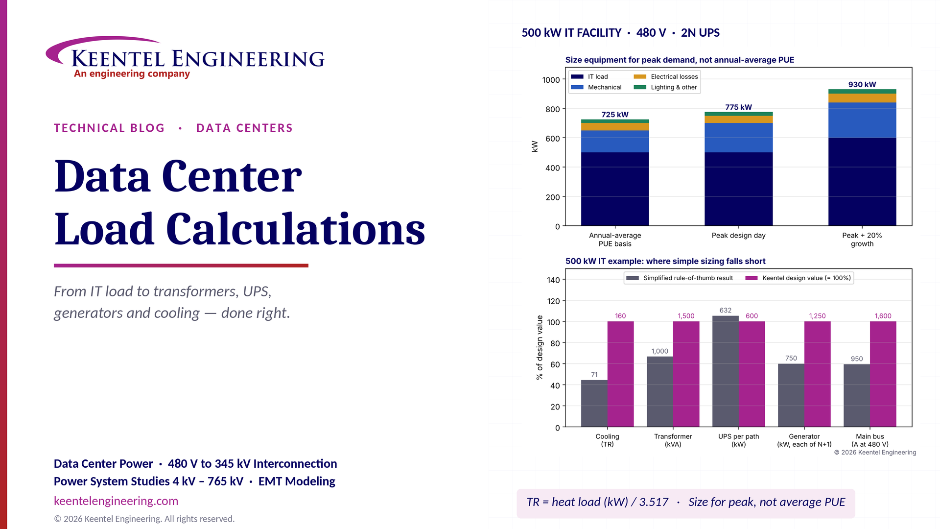
By SANDIP R PATEL
•
October 20, 2026
Learn data center electrical load calculations, including IT demand, PUE, UPS and generator sizing, cooling loads, redundancy, and worked US examples.
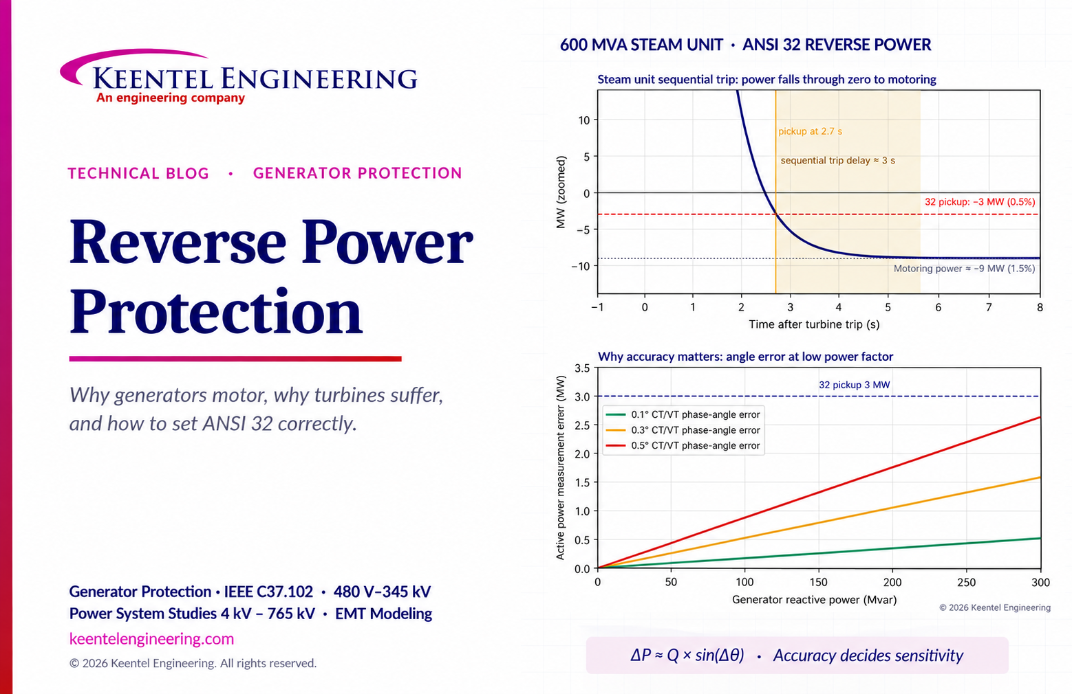
By SANDIP R PATEL
•
October 20, 2026
Learn reverse power protection (ANSI 32), generator motoring, relay pickup settings, time delays, sequential tripping and testing for US power plants.
Copy

By Team 2 Dexora
•
October 20, 2026
Explore grounding system testing with Keentel Engineering. Learn IEEE 80/81 methods, soil resistivity, ground resistance, and touch and step voltage safety.

By SANDIP R PATEL
•
October 13, 2026
Plan data center capacity with land screening, MW-per-acre estimates, grid power availability and interconnection feasibility studies from Keentel Engineering.

By SANDIP R PATEL
•
October 11, 2026
Learn which fault produces the highest current at a bus, why SLG faults can exceed three-phase faults, and how symmetrical components determine fault duty.

By SANDIP R PATEL
•
October 11, 2026
Learn why zero-sequence current pulsates in the dq0 frame, how Park's transformation works, and how inverter controls handle unbalance and ground faults.

By SANDIP R PATEL
•
October 11, 2026
Explore grid inertia, RoCoF and frequency response, with swing equation calculations, frequency nadir analysis and US power system simulation examples.

By SANDIP R PATEL
•
October 11, 2026
Learn transient stability analysis, swing equation, equal-area criterion and critical clearing time with a 345 kV worked example and NERC TPL-001 guidance.

By SANDIP R PATEL
•
October 11, 2026
Learn why inverter controls become unstable in weak grids, how PLL bandwidth and SCR affect stability, and how PSCAD EMT studies identify and mitigate oscillations.





