
A Coordinated Electric System Interconnection Review—the utility’s deep-dive on technical and cost impacts of your project.
Challenge: Frequent false tripping using conventional electromechanical relays
Solution: SEL-487E integration with multi-terminal differential protection and dynamic inrush restraint
Result: 90% reduction in false trips, saving over $250,000 in downtime
The three operating regions you have to design to
| Device | Output vs voltage | Response | Best suited to | Main limitations |
|---|---|---|---|---|
| Mechanically switched capacitor or reactor | Proportional to voltage squared | Seconds; discrete steps; limited switching operations per day | Steady-state reactive supply, voltage profile, loss reduction | No dynamic capability; step voltage change on switching; capability collapses when most needed |
| Static var compensator | Capacitive branches proportional to voltage squared | A few cycles; continuously controllable | Continuous control where cost matters and deep voltage support is not the driver | Square-law capability loss; harmonic filters are part of the plant and interact with the network |
| STATCOM | Approximately proportional to voltage — constant current capability | One to two cycles closed loop; converter response faster still | Voltage stability margin, weak interconnections, fast disturbance recovery, flicker and unbalance compensation | Higher capital cost; converter losses; adds a converter and its control dynamics to the network |
| Synchronous condenser | Governed by machine capability and excitation | Excitation response in the hundreds of milliseconds; inherent inertial response instantaneous | System strength and inertia, short-circuit contribution, black start support | Rotating plant with maintenance and losses; slower controlled response than a converter |
| STATCOM with energy storage | Reactive as a STATCOM, plus real power within the storage rating | As STATCOM for reactive; real power limited by storage | Where a real power deficiency is part of the problem | Cost and complexity of the storage; different failure and maintenance profile |
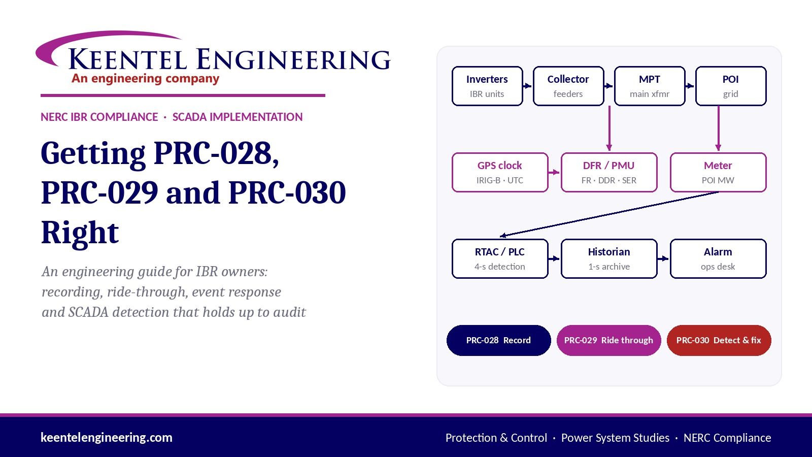
Getting PRC-028, PRC-029 and PRC-030 Right
An Engineering Guide for IBR Owners: recording, ride-through, event response and SCADA detection that holds up to audit
October 03, 2026 | Blog
Why this matters now
As of October 1, 2026, inverter-based resource (IBR) owners in North America are carrying three new obligations at once: record disturbances (PRC-028-1), stay connected through them (PRC-029-1), and detect, analyse and fix unexpected output losses (PRC-030-1). PRC-029-1 and PRC-030-1 both took effect on that date, and the PRC-028-1 recording deadlines for the existing fleet run through January 1, 2030.
These standards were written because inverter-based plants have tripped, curtailed or cut output in large numbers during ordinary grid faults. Losses of over 1,000 MW from a single fault have been recorded. NERC's response was to stop treating ride-through, recording and event follow-up as good practice and to make each one auditable.
The hard part is not reading the standards. It is proving them on a real plant, where the evidence sits in relay settings, recorder configuration files, PLC logic, historian archives and the clock that time-stamps all of it. A compliance claim is only as good as the weakest link in that chain.
This guide explains what the three standards require in engineering terms, where real plants fail them, how SCADA-based PRC-030 detection should be built and tested, and what to expect from an engineering partner. It closes with three anonymised case studies and a detailed FAQ.
The case studies in this guide are composite and illustrative. They are drawn from recurring patterns in field and design reviews and do not describe any specific client, site, project, manufacturer, integrator or utility.
The three standards in engineering terms
Each standard answers one question: PRC-028-1 asks whether you recorded the disturbance, PRC-029-1 asks whether you stayed on through it, and PRC-030-1 asks whether you noticed when you didn't and fixed the cause. They depend on each other: PRC-030 analysis is impossible without PRC-028 data, and PRC-029 performance is judged from the same records.
PRC-028-1: disturbance monitoring and reporting for IBRs
PRC-028-1 sets what an IBR facility must record, where, at what resolution, how accurately it is time-stamped, and how long it is kept.
| Requirement | What it asks for | Key numbers |
|---|---|---|
| R1 Sequence of events (SER) | Breaker positions for main transformers, collector buses, reactive devices; for IBR units, fault codes, fault alarms and voltage/frequency ride-through mode status | Triggered on ride-through or trip events |
| R2 Fault recording (FR) locations | Main transformer high side, collector feeder breakers, shunt dynamic reactive devices | Phase-to-neutral voltages, phase and residual currents, MW and Mvar |
| R3 FR performance | Triggered waveform records | At least 64 samples per cycle; at least 2.0 s total; at least 2 cycles pre-trigger; neutral overcurrent, over/under voltage and over/under frequency triggers |
| R4–R5 Dynamic disturbance recording (DDR) | Continuous recording at each main transformer | Input at least 960 samples/s; output at least 60 records/s; voltage, current, MW, Mvar, frequency |
| R6 Time synchronisation | All recording traceable to UTC | ±1 ms for substation devices; ±100 ms for IBR units |
| R7 Retention and provision | Data kept and handed over on request | 20 calendar days retrievable; provided within 15 calendar days; SER as CSV, FR/DDR as CSV or COMTRADE |
| R8 Loss of recording capability | Respond when a recorder fails | Restore within 90 days or file a Corrective Action Plan within 90 days |
Implementation is phased. New BES IBRs must comply with R1–R7 within 15 months of the effective date or by commercial operation, whichever is later. Existing BES IBRs must reach 50% compliance within three years of the effective date and 100% by January 1, 2030. R8 applied nine months after the effective date.
PRC-029-1: frequency and voltage ride-through
PRC-029-1 requires IBRs to stay connected and keep injecting current through defined voltage and frequency excursions. FERC approved it on July 24, 2025 (Order No. 909), and it took effect on October 1, 2026.
- Voltage ride-through: continuous operation between 0.90 and 1.05 per unit, with mandatory operation for defined cumulative durations below 0.90 pu and permissive operation only in the deepest band below 0.10 pu.
- Frequency ride-through: continuous operation from 58.8 to 61.2 Hz, ride-through of rate of change of frequency up to 5 Hz/s, and only narrow allowances for tripping on large phase-angle jumps.
- Recovery: real power restored promptly after voltage recovers, typically within 1.0 second.
- Exemptions: documented hardware limitations for in-service equipment, with documentation due within 12 months of the effective date. NERC filed PRC-029-2 on August 28, 2026 to widen exemptions for long-lead projects and HVDC-connected IBRs.
The practical point: a plant can have compliant inverters and still fail PRC-029 because a relay, a plant controller limit or a utility-side element trips first.
PRC-030-1: unexpected IBR event mitigation
PRC-030-1 turns event follow-up into a four-step, time-boxed process. It took effect on October 1, 2026.
| Requirement | What it requires | Deadline |
|---|---|---|
| R1 Detection | A documented process to identify complete loss of output, or real-power changes of at least 20 MW and at least 10% of gross nameplate within any 4-second period, with defined exclusions | Continuous |
| R2 Analysis | Root cause, ride-through performance, performance issues, and applicability to other plants | 90 calendar days from the event |
| R3 Corrective action | Corrective Action Plan, or technical justification for not acting, shared with the RC, BA and TOP | 60 calendar days after R2 |
| R4 Implementation | Carry out the CAP, update it when it changes, notify the RC on changes and completion | Per the CAP |
The R1 test is conjunctive: both 20 MW and 10% must be met. On a 90 MW plant the 20 MW figure governs; on a 300 MW plant 10% (30 MW) governs. The exclusions cover resource variability, dispatch and ramping, planned outages and testing, transmission or collector losses, and protection misoperations handled under PRC-004.
ERCOT overlays
In ERCOT, NOGRR255 adds requirements on top of PRC-028-1 for
disturbance monitoring, and NOGRR245 adds ride-through requirements alongside PRC-029-1. Under NOGRR255 as we apply it, fault recording for newer equipment is held to 128 samples per cycle, total record length to at least 5 seconds (we design to 6), rolling retention to 30 days and data delivery to 7 calendar days. ERCOT values should always be confirmed against the current Nodal Operating Guides before design.
Where compliance actually breaks
Most IBR plants that fail these standards have the right equipment and the wrong configuration, data path or evidence. Below are the failure modes we find most often, grouped by where they sit.
| # | Failure mode | Why it fails the standard | How it is caught |
|---|---|---|---|
| 1 | Relay event reports offered as the fault recorder | Typical relay records are 4–16 samples per cycle and 0.25–1 s long, below the PRC-028 floor of 64 samples per cycle and 2 s (and ERCOT's 128 and 5 s) | Read the event-report settings and a real record; compare sample rate, length and pre-trigger to R3 |
| 2 | Fault recorder triggers built only on fault detectors | R3 requires neutral overcurrent, over/under voltage and over/under frequency triggers; a fault-only trigger misses ride-through excursions | Read the trigger equations (relay ER logic or DFR trigger table) element by element |
| 3 | PMU-capable relays assumed to provide DDR | Capability is not configuration. DDR needs a continuous stream, a defined rate, and an archive with retention | PMU and PDC configuration exports, stream rate, archive settings, a sample record |
| 4 | Recorders with no automated retrieval | Count-limited on-board storage overwrites records before 20 or 30 days; dial-up or laptop-only retrieval cannot meet a 7- or 15-day delivery reliably | Network diagram, firewall rules, retrieval software inventory, retention arithmetic |
| 5 | Time synchronisation present but unsupervised | IRIG-B wired to every device does not prove ±1 ms. Lost satellite lock or a bad time-quality bit goes unnoticed | Clock status, time-quality bits in actual records, a clock-failure alarm mapped to SCADA |
| 6 | Inverter SER without native time stamps | Fault bits polled by a PLC every few seconds carry the poll time, not the event time; ride-through mode status is often not mapped at all | Point list review, polling rate, inverter clock source, OEM documentation |
| 7 | Plant MW signal slower than the historian | A 1-second historian archive of a value that updates every 2–3 seconds stores repeated values, and a 4-second detection window loses resolution | A raw (non-aggregated) export of the MW tag; DNP3 class, deadband and poll settings along the path |
| 8 | Inverted logic in detection or supervision | A missing negation can make a PRC-030 trigger fire only when communications fail, or an alarm sit on in normal operation | Tracing the compiled logic file, not screenshots: wiring, negation flags, execution order |
| 9 | Protection tripping inside the ride-through envelope | A plant or gen-tie relay undervoltage element (for example 0.90 pu, 1.0 s) can trip the plant in the PRC-029 mandatory-operation zone even when inverters comply | Settings review of every element between the inverter and the POI against the ride-through curves |
| 10 | Evidence that cannot be audited | Aggregated exports, screenshots without time stamps, test-period alarms left undocumented, test mode left enabled | A defined evidence package: raw exports, alarm journals, as-left files, signed test logs |
Two patterns run through the list. First, capability is not compliance: a PMU-capable relay, a networked recorder or a fast meter proves nothing until its configuration and an actual record show it working. Second, the chain fails at the handoffs: between the meter and the RTAC, the RTAC and the PLC, the PLC and the historian, the clock and the recorder. Each device can be correct while the system is not.
We also separate three kinds of evidence, because confusing them causes both false deficiencies and false confidence:
- Installed capability: drawings, device models, as-left settings and configuration files.
- Ongoing operating evidence: historian archives, recorder and SER files, alarm histories, screening records, retention logs.
- Event-driven evidence: PRC-030 R2 analyses, Corrective Action Plans and their implementation. If no qualifying event has occurred, the absence of an R2 analysis is not a deficiency.
SCADA implementation done right
A defensible PRC-030 R1 implementation is a measured data path, a small piece of deterministic logic, an archive and an alarm route, each verified end to end. The logic itself is rarely more than 30 function blocks. The work is in making every link provable.
1. Start from the measurement, not the logic
- Pick the source deliberately. Use the POI revenue or check meter's real power (net or gross, documented), not a computed sum of inverter outputs, which drops out when inverter communications fail.
- Measure the update rate where the logic runs. A meter may update its MW register every 200 ms, but by the time the value has crossed a substation RTAC, a SCADA RTAC and a serial DNP3 link to a PLC, it can arrive every 2–3 seconds. Our acceptance target is at least 1 Hz at the PLC or RTAC tag.
- Check every hop for deadband and event-only reporting. DNP3 analog deadbands, class assignments and event buffers are the usual culprits. Integrity or continuous polling with unsolicited responses, and a deadband near zero on the MW point, fix most cases.
2. Build the detection logic to the standard's geometry
R1 says "within a 4-second period", which means any 4-second window, not fixed 4-second blocks. A single sample-and-hold register every 4 seconds misses a 22 MW drop split 12/10 across the boundary.
- Rolling window: a 1-second self-resetting clock shifts the current value into a four-stage register (1, 2, 3 and 4 seconds ago). The register must execute oldest-first; if the newest copy runs first, all four stages hold the same value and the window collapses to about 1 second.
- Four comparisons: subtract each stored value from the current value, take the absolute value, and compare each against the threshold. The standard says "changes", so detection should be direction-neutral unless a documented basis says otherwise.
- Conjunctive threshold: set the threshold to the larger of 20 MW and 10% of verified gross nameplate. If the nameplate is not verified, do not hard-code the number.
- Hold the trigger: a pulse timer of about 5 seconds keeps the trigger visible to a 1-second historian and to the alarm system.
3. Supervise the data, not just the device
- Communications permissive: AND the trigger with a "communications healthy" signal built from every stage of the path. At least one status must be generated by the device running the logic itself (its own driver or heartbeat), because a status polled over the link it supervises freezes "healthy" when that link dies.
- Restore delay: after communications return, the stored samples are stale for up to 4 seconds. A restore delay of about 5 seconds before re-arming prevents a false trigger on the first fresh sample.
- Separate communication alarm: loss of supervision must alarm on its own, distinct from the event trigger, with its polarity documented.
- Optional total-loss flag: a supplemental flag for complete loss at low output (below the R1 threshold) is useful operationally. It should use the same 4-second window and the same communications permissive, and stay separate from the R1 trigger.
4. Archive and alarm for evidence
- Archive at 1 second with deadband off: the MW source, the computed changes, the trigger, the communication alarm and the communication statuses. Retain at least 90 days of 1-second data.
- Export raw values: time-averaged or interpolated exports are not evidence of what the plant did. Raw-value exports for a ±10-minute window should be a documented, tested procedure.
- Route the alarm beyond the HMI: a remote operations desk and a named notification list, with an alarm on bad data quality as well as on value.
- Time stamps that trace to UTC: GPS clock to RTAC by IRIG-B, RTAC to PLC and historian by SNTP or better. One second matters here; one millisecond does not.
5. Test it like protection
Every implementation should have a test mode that substitutes a test MW value, plus a witnessed or evidence-backed test plan:
| Test | Expected result |
|---|---|
| Step of 25 MW (or 1.25 × threshold) | Trigger asserts and holds |
| Ramp of just over threshold across about 3 s | Trigger asserts (rolling window) |
| Threshold split across a sample boundary | Trigger asserts |
| Increase of just over threshold | Trigger asserts (direction-neutral) |
| Step below threshold; slow ramp over more than 4 s | No trigger (selectivity) |
| Communication failure on each stage | Trigger suppressed; communication alarm raised; re-arm after the restore delay |
| Healthy steady state | No alarms active |
| Raw historian query of the test window | Events present at 1-second resolution with correct time stamps |
| End-to-end retrieval by the operations team | Event exported with their own credentials |
Two procedural rules prevent most test-day problems. Set the test value equal to live output before enabling test mode, so entering and leaving test mode does not itself trigger. And record the time test mode was switched off, with data proving the logic is back on the live meter.
Case study 1: Four logic revisions to a PRC-030 trigger that works
Composite and illustrative. Not a description of any specific client, site, integrator or project.
Situation. A utility-scale solar plant of under 100 MW needed PRC-030-1 R1 detection in place by the effective date, with about three weeks to go. The plant's SCADA integrator was to program the logic in the plant controller (a PLC). The engineering firm's role was to set the design basis, review each logic revision and verify the deployment evidence.
Approach. Every revision was reviewed from the compiled project file itself: wiring, negation flags and the controller's execution (solve) order were read out block by block. Screenshots were used only as a cross-check.
What the reviews found.
| Revision | Finding | Effect if deployed | Fix |
|---|---|---|---|
| 1 | The four-stage sample register executed newest-first | All four stored values equalled the latest sample; the 4-second window shrank to about 1 second and missed ramps over 2–4 seconds | Reverse the execution order (oldest first) |
| 2 | The communications permissive lost its negation when three status bits were combined | The trigger could only fire when communications had failed | Restore the negation |
| 2 | One of the three status bits had the opposite polarity to the others | It masked the first error: a functional test would have passed with both defects present | Correct both together, add a healthy-state test |
| 3 | The communication alarm was wired from the "healthy" signal | Alarm on in normal operation, off on a real failure | Invert at the alarm system, with polarity and bad-quality alarming documented |
| Deployed | A raw historian export showed the plant MW value updating every 2–3 s, not every second | Ramp events developing over 3–4 s could be delayed or missed; step events still caught | Logged as a medium-priority corrective action on the upstream data path |
Deployment verification. The test results were checked second by second against the historian export. Every intended test passed, including a direction-neutral increase and suppression during a simulated communication failure. The review also found that four of eight trigger alarms in the test window came from entering and leaving test mode, and that the export ended with test mode still enabled. A time-stamped screenshot showing the controller logic equal to the reviewed file, and the time test mode was switched off, closed both points. Live output during the test-mode period never changed by more than about 2 MW in 4 seconds, so no real event was masked.
Result. Detection was in service before the effective date, with one documented corrective action and an evidence package an auditor can follow.
Lesson. The two most serious defects would have passed a casual functional test because they cancelled each other. Reviewing the compiled logic, not the screen capture, is what found them.
Case study 2: "We record everything through the RTAC"
Composite and illustrative. Not a description of any specific client, site, manufacturer or project.
Situation. A large solar facility with no dedicated disturbance recorder reported that its PRC-028 approach was "RTAC event-based collection of relay event records and SER." The owner wanted to know whether that claim would hold up, and what would be needed if it did not.
Approach. Rather than argue from the architecture drawing, the review asked for the records themselves. The owner provided about 30 relay event files from line, bus, transformer and feeder relays, plus the as-built protection and communications drawings and the RTAC project exports.
What the records showed.
| Check | Finding | Against PRC-028-1 |
|---|---|---|
| Sample rate | 4 samples per cycle on most relays; one bus relay produced 2 kHz COMTRADE | R3 requires at least 64 samples per cycle |
| Record length | 0.25 to 1.0 s; the longest setting allowed 60 cycles | R3 requires at least 2.0 s total |
| Continuous recording | None; all records event-triggered | R4–R5 require continuous DDR at the main transformer |
| Time synchronisation | IRIG-B with time-quality supervision visible inside actual records | Strong supporting evidence for R6 |
| SER | Relay SER present; inverter fault and ride-through status not in any record | R1 requires IBR unit fault codes and ride-through mode status |
| Retrieval and retention | Depended on RTAC collection settings and a historian whose retention was unstated | R7: 20 days retrievable, 15-day delivery |
What the gap assessment concluded. Relay-native records could support SER and time-synchronisation evidence, but could not be the fault-recording basis at any site, and certainly not under ERCOT's tighter rules. The facility needed either dedicated fault and dynamic recording at the main transformers and feeders, or a demonstrated relay-plus-PMU design meeting the rates, lengths and continuous recording the standard requires. The RTAC collection configuration and historian retention moved to the top of the information request, because the whole recording claim rested on them.
A contrasting case. At a second facility, two dedicated recorders were already on the station network and their failure alarms were mapped to SCADA. The gap there was narrower: no retrieval software was installed, so 20- or 30-day retention depended on the recorders' own storage. The fix was software and firewall configuration, not new hardware.
Lesson. "We record everything" is a hypothesis. Thirty real event files answered in a day what an architecture debate would not have settled in a month, and they also produced positive evidence (time quality) the owner had not known it had.
Case study 3: Compliant inverters, a gen-tie that trips first
Composite and illustrative. Not a description of any specific client, site, manufacturer, utility or project.
Situation. A large battery storage plant was preparing its PRC-029-1 ride-through evaluation. The inverter manufacturer had supplied standard settings, and the owner wanted them checked before the as-built settings were finalised.
Approach. The review followed the fault current path from the inverter to the point of interconnection and listed every element that could disconnect the plant during a voltage or frequency excursion: inverter protective functions, plant controller limits, collector and main transformer relays, the plant-end gen-tie relay, and the utility's line relays at the interconnection substation.
What the review found.
- Inverter settings. Most manufacturer defaults sat outside the ride-through envelope, but several needed site-specific values. Each field on the as-built settings form got a default, a recommended value, an action and a reason, so the owner could sign off line by line.
- Utility line relay. The utility's gen-tie relays carried a positive-sequence undervoltage element at 0.90 pu with a 1.0 s definite time. PRC-029 requires continuous operation down to 0.90 pu and mandatory operation below it for cumulative periods measured in seconds. A sustained sag to 0.85 pu would therefore trip the gen-tie, and the whole plant with it, inside the zone where the plant is required to stay on.
- Ownership disagreement. The construction contractor proposed a much lower, slower setting. The utility declined, on the basis that ride-through and protection-coordination obligations apply to the generator's protection, not to transmission-owned line relays.
Why it matters even when the relay is not the owner's. In a real event the plant would disconnect, the output loss could cross the PRC-030 threshold, and the owner would be the one documenting the event, the root cause and the response. A gen-tie trip may fall under the PRC-030 transmission-loss exclusion, but the owner still has to evidence that classification. The owner is also the one whose PRC-029 performance record shows a trip.
Path forward.
- Put the conflict in writing: the element, the ride-through curve it intersects, and the voltage-time zone affected.
- Ask the utility for a coordination study or a revised delay that keeps the element outside the mandatory-operation region while still meeting its own protection objectives.
- Set every plant-owned element (inverter, plant controller, plant-end relays) clear of the envelope with margin, and document it.
- Keep the technical record ready, so that if a trip occurs, the PRC-030 analysis can show the cause in days, not months.
Lesson. Ride-through compliance is a property of the whole connection, not of the inverter datasheet. The review must reach the last relay before the grid, including the ones the owner does not set.
Why Keentel Engineering
Keentel Engineering is a P.E.-led power systems firm that works at the exact junction where these three standards are won or lost: protection settings, disturbance recorders, station automation, SCADA logic and the evidence that ties them together. Most firms cover one side of that junction. We cover all of it, from the relay trip equation to the historian export.
What sets the work apart
| Differentiator | What it means in practice |
|---|---|
| We verify from source files, not screenshots | PLC and RTAC project files, relay settings databases, recorder configuration files and raw historian exports are traced element by element. Case study 1 is why: the worst defects only show up in the compiled file. |
| One team across all three standards | PRC-028 recording, PRC-029 ride-through and PRC-030 event response are assessed as one system, so a recorder gap or a relay setting found in one is carried into the other two. |
| Protection engineers who read SCADA logic | We design detection logic, review integrator code revision by revision, and write the test plan an auditor can follow. We do not need the integrator to translate. |
| Records over claims | We ask for real event files, raw exports and as-left settings early. A day of record review routinely settles questions that architecture discussions cannot. |
| Evidence classified correctly | Installed capability, ongoing operating evidence and event-driven evidence are kept separate, so owners are neither marked deficient for events that never happened nor reassured by hardware that was never configured. |
| ERCOT and non-ERCOT fluency | NOGRR255 and NOGRR245 overlays are applied where they apply and kept out where they do not. |
| Vendor-neutral | SEL, GE, ERLPhase and other platforms; any SCADA integrator; any inverter OEM. Our interest is that the plant complies, not that a product is sold. |
| Engineering only, when that is what you need | We can design and verify while your incumbent integrator implements, which avoids re-commissioning systems that already work. |
Firm credentials
- Founded and led by Sandip R. Patel, P.E., IEEE Senior Member.
- Power system studies, protection and control, and substation work from 4 kV to 765 kV.
- Four service lines under one roof: electrical design, power system studies, NERC compliance, and QA/QC.
- Offices in Tampa (HQ), Austin, Sacramento and Baltimore; NSPE member firm, D-U-N-S registered, BBB A+ accredited.
- Utility-scale solar, wind and BESS engineering, EMT modelling, owner's engineer services and interconnection engineering, so findings connect to the models and agreements that govern the plant.
What you receive
- PRC-028-1 / NOGRR255: hardware verification report, software and configuration assessment, recorder and DDR gap analysis, time-synchronisation review, retrieval and retention design, disturbance monitoring SOP, R8 response procedure.
- PRC-029-1 / NOGRR245: inverter, plant controller and relay settings review against the ride-through curves; field-by-field settings recommendations; exemption documentation support; coordination findings for elements owned by others.
- PRC-030-1: R1 design basis and threshold determination; detection logic design or independent QA/QC of an integrator's logic; data-path and update-rate verification; test plan and readiness memo; R2 analysis framework, R3 CAP and technical-justification templates, R4 tracking; O&M evidence and retention matrix.
- SCADA implementation support: RTAC, PLC and historian requirements, alarm and notification design, communications supervision, and witnessed or evidence-based acceptance testing.
Frequently asked questions
PRC-028-1: disturbance monitoring
1. Can protective relays serve as our fault recorder?
Only if their records meet R3: at least 64 samples per cycle, at least 2.0 seconds total, at least two cycles pre-trigger, and the required triggers. Many relays can be configured close to this; few are by default. In ERCOT the bar under NOGRR255 is higher (128 samples per cycle and at least 5 seconds as we apply it), which most relay event reports cannot reach.
2. Do we need a dedicated DDR, or can PMUs do it?
PRC-028 sets performance, not product. Relays streaming synchrophasors to a phasor data concentrator can satisfy DDR if the stream carries the required quantities, the output rate is at least 60 per second, recording is continuous, and the archive meets retention. PMU capability without an enabled stream and an archive does not count.
3. What exactly must the SER capture at the inverter level?
R1 requires IBR unit fault codes, fault alarms, and voltage and frequency ride-through mode status, captured when ride-through or tripping occurs. Many plant SCADA point lists carry fault bits but no ride-through mode status, and time-stamp them at the PLC poll rather than at the inverter.
4. How accurate does time synchronisation need to be?
±1 ms of UTC for substation recording devices and ±100 ms for IBR units. In practice that means a GPS clock with IRIG-B to relays and recorders, time-quality supervision, and an alarm on loss of satellite lock.
5. How long must records be kept, and how fast must we provide them?
Under PRC-028-1, data must be retrievable for 20 calendar days and provided within 15 calendar days of a request. In ERCOT we apply 30 days of rolling retention and 7-day delivery. Recorders with count-limited storage and no automated retrieval are the usual weak point.
6. When do existing plants have to comply?
Existing BES IBRs must reach 50% compliance with R1–R7 within three years of the effective date and 100% by January 1, 2030. New BES IBRs comply within 15 months of the effective date or at commercial operation, whichever is later. R8 (responding to failed recording capability) already applies.
7. What happens if a recorder fails?
Under R8 you restore recording capability within 90 calendar days, or submit a Corrective Action Plan to your Regional Entity within 90 days and implement it. That makes recorder health alarms in SCADA a practical necessity, not a nicety.
PRC-029-1: ride-through
8. Our inverters are certified for ride-through. Are we compliant?
Not necessarily. Compliance is a property of the whole connection. Plant controller limits, collector and transformer relays, gen-tie relays and utility-owned elements can all trip the plant inside the ride-through envelope.
9. What are the key PRC-029 numbers?
Continuous operation from 0.90 to 1.05 pu and 58.8 to 61.2 Hz; mandatory operation for defined cumulative durations below 0.90 pu; ride-through of rate of change of frequency up to 5 Hz/s; prompt recovery of real power after voltage recovers. Exact curves and cumulative timing come from the standard's attachments.
10. Can we get an exemption?
In-service equipment with documented hardware limitations can be exempted, with documentation due within 12 months of the October 1, 2026 effective date. Software-fixable limitations do not qualify. PRC-029-2, filed August 28, 2026, would widen exemptions for certain long-lead projects and HVDC-connected IBRs.
11. How does PRC-029 interact with PRC-028?
PRC-029 performance is judged from disturbance records, so the phased performance requirements track PRC-028 recorder implementation. Without compliant recording you cannot demonstrate compliant ride-through.
PRC-030-1: unexpected event mitigation
12. What counts as a qualifying event under R1?
Complete loss of facility output, or a real-power change of at least 20 MW and at least 10% of gross nameplate within any 4-second period, excluding variability of the resource, dispatch and ramping, planned outages and testing, transmission or collector system losses, and protection misoperations under PRC-004.
13. Why does "any 4-second period" matter so much?
It means a rolling window. Logic that samples every 4 seconds and compares adjacent samples misses events split across the sampling boundary. A 1-second shift register comparing current output with 1, 2, 3 and 4 seconds ago closes that gap.
14. Should detection be direction-neutral?
The requirement says changes, and a sudden increase can also indicate abnormal behaviour. Taking the absolute value costs nothing in logic. If an owner chooses drop-only detection, the basis should be documented.
15. How fast must the MW signal update?
We set at least 1 Hz at the device running the logic. Measure it there, with a raw historian export, not at the meter. Multi-hop paths through RTACs and serial links commonly deliver 2–3 seconds.
16. Can R1 be done manually by reviewing trends?
The standard requires a documented process, not automation. But manual review of every 4-second window is impractical and hard to evidence. Automated detection with alarming and archiving is the defensible approach for most plants.
17. What are the R2–R4 deadlines?
R2 analysis within 90 calendar days of the event; R3 Corrective Action Plan or technical justification within 60 days of completing R2, shared with the RC, BA and TOP; R4 implementation per the CAP, with the RC notified of changes and completion.
18. We have had no qualifying events. Are we non-compliant without an R2 analysis?
No. R2–R4 are event-driven. What must exist is the R1 process, the data to support an analysis, and the procedure to run one. The absence of an analysis for an event that never happened is not a deficiency.
19. Who should own PRC-030 R2 analysis?
The Generator Owner is accountable. Operationally, R2 needs someone who can read recorder files, relay events, inverter logs and plant controller data together, which is why many owners pair their O&M provider's data capture with an engineering firm's analysis.
Working with Keentel
20. Can you work with our existing SCADA integrator?
Yes. We commonly provide the design basis and independent QA/QC while the incumbent integrator implements, which avoids duplicate programming and keeps warranty responsibilities clear.
21. What do you need from us to start?
As-built protection and metering single lines, relay settings files, recorder configuration exports and a few sample records, RTAC and PLC project files, the SCADA point list and IP list, historian retention settings, and inverter OEM documentation. A first review often starts from whatever subset exists.
22. How long does an assessment take?
A focused PRC-030 R1 design basis and logic review can be done in two to three weeks when files are available. A full PRC-028 hardware and software assessment typically runs four to eight weeks, driven mostly by how quickly settings, configurations and records arrive.
23. Do you only do assessments, or implementation too?
Both. We can assess and recommend, design and specify, or support implementation with testing and readiness documentation. Physical installation and integrator programming can stay with your existing contractors.
Getting started
The fastest route to a defensible position is a short, file-based review: send what you have, and we will tell you within days which parts of PRC-028, PRC-029 and PRC-030 your plant already proves, which it only claims, and what it would take to close the gap. Where you have an incumbent SCADA integrator, we will work alongside them.
Keentel Engineering · 400 N Ashley Dr, Suite 2600, Tampa, FL 33602 · (813) 389-7871 · contact@keentelengineering.com · Offices in Tampa, Austin, Sacramento and Baltimore
Sources
- NERC PRC-028-1, Disturbance Monitoring and Reporting Requirements for Inverter-Based Resources
- NERC Project 2021-04, PRC-028-1 Implementation Plan
- NERC PRC-030-1, Unexpected Inverter-Based Resource Event Mitigation
- NERC petition for approval of PRC-029-2 (August 28, 2026), including PRC-029-1 status and dates
Disclaimer
This article is general technical information, not legal advice or a compliance determination for any facility. Requirements are summarised; the governing text is the current NERC Reliability Standard, its implementation plan, and for ERCOT facilities the current Nodal Operating Guides. Applicability depends on registration and facility characteristics. The case studies are composite and illustrative: they do not describe any specific client, site, project, manufacturer, integrator or utility. Product names are trademarks of their owners, used for identification only, and imply no affiliation or endorsement.

About the Author:
Sandip "Sonny" R. Patel, P.E.
IEEE Senior Member · Founder & CEO, Keentel Engineering
In 1995, Sonny Patel earned his Electrical Engineering degree from the University of Illinois. But degrees don't build legacies — action does.
For three decades, he has worked the power industry from every side of the table: 16 years as a utility engineer at Exelon/Commonwealth Edison; generation leadership across hydroelectric, industrial steam turbine, and a 9 GW renewable fleet; NERC Regional Entity Senior Compliance Engineer and Audit Team Lead, auditing some of the nation's largest utilities; and testing and commissioning lead on equipment up to 765 kV — the very top of the North American grid.Utility. Generator. Regulator. Consultant. Few engineers have seen all four seats. Fewer still have sat in them.
His experience spans nuclear, hydro, conventional generation, renewables, oil and gas, mining — and today's data centers, where he is authoring a three-book series on data center design. He is a Licensed Professional Engineer in six states and a Licensed Electrical Contractor in Florida (Unlimited EC) — he doesn't just design the work; he's qualified to stand behind its execution.Today, as Founder and CEO of Keentel Engineering, Sonny leads a nationwide team of engineers delivering substation design, power system studies, NERC compliance, and commissioning — done right, coast to coast.Three decades. Every side of the table. One standard: accountable engineering.
Services

Let's Discuss Your Project
Let's book a call to discuss your electrical engineering project that we can help you with.
About the Author:
Sandip "Sonny" R. Patel, P.E.
IEEE Senior Member · Founder & CEO, Keentel Engineering
In 1995, Sonny Patel earned his Electrical Engineering degree from the University of Illinois. But degrees don't build legacies — action does.
For three decades, he has worked the power industry from every side of the table: 16 years as a utility engineer at Exelon/Commonwealth Edison; generation leadership across hydroelectric, industrial steam turbine, and a 9 GW renewable fleet; NERC Regional Entity Senior Compliance Engineer and Audit Team Lead, auditing some of the nation's largest utilities; and testing and commissioning lead on equipment up to 765 kV — the very top of the North American grid.
Utility. Generator. Regulator. Consultant. Few engineers have seen all four seats. Fewer still have sat in them.
His experience spans nuclear, hydro, conventional generation, renewables, oil and gas, mining — and today's data centers, where he is authoring a three-book series on data center design. He is a Licensed Professional Engineer in six states and a Licensed Electrical Contractor in Florida (Unlimited EC) — he doesn't just design the work; he's qualified to stand behind its execution.
Today, as Founder and CEO of Keentel Engineering, Sonny leads a nationwide team of engineers delivering substation design, power system studies, NERC compliance, and commissioning — done right, coast to coast.Three decades. Every side of the table. One standard: accountable engineering.
Leave a Comment
Thank you for contacting us.
We will get back to you as soon as possible.
We will get back to you as soon as possible.
Oops, there was an error sending your message.
Please try again later.
Please try again later.
Related Posts

By SANDIP R PATEL
•
October 3, 2026
A practical guide to SSO classification, SSR, PEDI, Wind-SSCI, EMT analysis, mitigation and protection based on CIGRE TB 909.

By SANDIP R PATEL
•
October 3, 2026
Learn how PV string I-V curve testing identifies hidden solar performance losses, including soiling, shading, mismatch, degradation, and wiring faults.

By SANDIP R PATEL
•
October 3, 2026
Learn how active harmonic filters work, how to size AHF systems, reduce VFD harmonics, calculate losses, and meet IEEE 519 TDD limits at the PCC.

By SANDIP R PATEL
•
October 3, 2026
Learn how BESS supports grid stability through fast frequency response, voltage support, oscillation damping, black start, grid-forming controls and EMT studies.

By SANDIP R PATEL
•
September 30, 2026
Learn NERC and ERCOT compliance requirements for natural gas power plants, including GO/GOP obligations, O&P standards, GADS reporting, and audits.

By SANDIP R PATEL
•
September 26, 2026
Learn how to prepare a MISO large-load interconnection package, including PSS®E models, BESS smoothing, harmonic data and transmission-owner requirements.

By SANDIP R PATEL
•
September 26, 2026
Learn where storage belongs in an 800 VDC AI data center, including capacitors, flywheels, BESS, fault current, protection, grounding, and EMT design.

By SANDIP R PATEL
•
September 26, 2026
Learn how SPP’s HILL and HILLGA framework works for large-load projects, including studies, BTM generation, modeling, EMT requirements, and firm service.

By SANDIP R PATEL
•
September 25, 2026
Learn how IBR time synchronization, IEEE 2800, IRIG-B verification, and PTP solutions help meet disturbance monitoring compliance requirements.





