
A Coordinated Electric System Interconnection Review—the utility’s deep-dive on technical and cost impacts of your project.
Challenge: Frequent false tripping using conventional electromechanical relays
Solution: SEL-487E integration with multi-terminal differential protection and dynamic inrush restraint
Result: 90% reduction in false trips, saving over $250,000 in downtime
ERCOT enforces all of the above through simulation, which means your model is your compliance case. The bar is now high:
- Whole-facility scope. The model must represent everything the IT load, the UPS and power conversion, the cooling plant, the protection and control systems in formats compatible with ERCOT's study platforms (PSS/E, PSCAD, TSAT).
- Real control loops, not approximations. Generic textbook representations are unacceptable. The model must capture the actual inner control behavior of your power electronics.
- Hardware-validated converter models. For electronic loads, the PSCAD model must be benchmarked against actual hardware testing including voltage ride-through and subsynchronous response. A model assembled from standard PSCAD library blocks fails by definition, because a generic block has never been tested against your vendor's hardware. The good news: validation is a hardware-type test, so results for a given converter product are reusable across every facility that uses it.
- Format migration. Facilities that previously submitted the older composite load model (CMLD) format must transition to EPRI's PERC1 format.
- Three checkpoints. Models are reviewed before the stability study begins (no model, no study), before each quarterly stability assessment, and for electronic loads one final time before energization, when you must submit as-built models with a documented comparison against the previously studied data and a sworn attestation that the model matches actual field settings. ERCOT's review takes 10 business days, extendable by 20 put it on your critical path.
- A living obligation. Change your technology, controls, or relay settings in a way that affects ride-through including converting a crypto mining site to an AI data center — and you've triggered a new interconnection study, even if your megawatts don't change.
| Parameter | Detail |
|---|---|
| System | 230 kV / 138 kV transmission corridors, wind and wet-snow icing exposure |
| Data basis | 15 years of minute-resolution forced-outage records + regional weather observations |
| Core methods | Event grouping, MVA performance curves, time-to-95%-restore, area outage rate curves, fragility modeling, rerun-history benefits, exceedance and log-domain risk metrics |
| Headline result | ≈85% of maximum resilience benefit at 60% of original capital; worst-event restoration window cut from 11 days to 5 in rerun-history terms |
| Decision supported | Capital portfolio selection; resilience plan filing; post-investment verification framework |
| System / Topic | Governing Standard(s) | What It Controls |
|---|---|---|
| Overall plant electrical distribution | IEEE 141 (Red Book); IEEE 666 | Distribution architecture, voltage selection, design of generating station auxiliary service systems |
| Power system studies | IEEE 399 (Brown Book); IEEE 551 | Load flow, symmetrical/asymmetrical short circuit, motor starting methodologies down to the lowest LV panelboard |
| Protection & coordination | IEEE 242 (Buff Book); IEEE 3004.5; IEEE C37 series | Generator relaying (21, 59N, 87G), time-current coordination, selective clearing between LV and MV tiers |
| GSU / UAT / SST transformers | IEEE C57.12.00 and C57 family | Transformer ratings, impedance, testing, loading |
| HV switchyard breakers | IEEE C37.06 | AC high-voltage circuit breaker preferred ratings |
| MV switchgear (13.8 kV) | IEEE C37.20.2; IEEE C37.20.7 | Metal-clad construction, compartmentalization, vacuum breakers; arc-resistant design with plenum venting |
| MV cable | UL 1072; ICEA S-93-639 (NEMA WC 74) | Type MV-105 shielded cable, 133% insulation level for HRG systems |
| LV switchgear (480 V) | IEEE C37.13; UL 1558 | Metal-enclosed LV power circuit breaker switchgear to 635 V, draw-out ACBs with electronic trip units |
| Motor control centers | UL 845; NEMA ICS 18 | LV-MCC construction, MCCB/MCP protection for motors under ~200 HP |
| Motors | NEMA MG-1 | Motor performance, starting characteristics, service factors |
| DC & battery systems | IEEE 485; IEEE 946 | Lead-acid battery sizing (125/250 VDC), DC auxiliary system design |
| Grounding | IEEE 80; IEEE 142 (Green Book) | Ground grid step/touch potential limits; system grounding including high-resistance grounding |
| Lightning protection | IEEE 998 | Direct-stroke shielding of switchyard and outdoor generator structures |
| Arc flash & electrical safety | IEEE 1584; NFPA 70E | Incident energy calculation; worker safety boundaries and PPE |
| Fire protection | NFPA 850 | Fire protection and risk management for combustion turbine generating plants |
| Installation code | NEC (NFPA 70); NESC | Wiring methods inside the plant fence; overhead/outdoor clearances at the switchyard |
| Interconnection & compliance | FERC LGIP; NERC MOD-025/026/027, PRC-019/024/029, FAC-008 | Interconnection process, model validation, protection/ride-through coordination, facility ratings |
| IFC / Construction Deliverable | Purpose |
|---|---|
| Stamped IFC packages | Legal basis for construction; P.E. responsible charge |
| Final relay settings & TCCs | Protection as-installed matches the coordination study |
| Calculation archive | Owner records; NERC audit evidence trail |
| Commissioning procedures | Safe, sequenced energization; MOD field testing |
| Construction support | RFIs, field changes, FAT/SAT witness |
| As-builts & model handoff | Operating baseline; future study currency |
| Metric | Outcome |
|---|---|
| Defects found pre-occupancy | Three topology defects and one settings-mismatch family corrected before load migration; the shared-switchboard defect alone would have invalidated the concurrently-maintainable claim on day one |
| IST findings | Fourteen additional discrepancies surfaced under scenario testing (control logic, alarm mapping, one generator sequencing fault) — all closed before handover instead of during operations |
| Black-building test | Passed on second execution; the first attempt exposed the generator sequencing fault under true block load, exactly the failure the compressed plan would never have found |
| Handover quality | Operations team certified on the actual failure scenarios; corrected EOPs and settings documentation delivered as controlled documents |
| Business outcome | Occupancy proceeded three weeks behind the original date — against an independent estimate that the uncorrected sequencing fault carried a high probability of a full facility outage within the first year |
Part 2 — Frequently Asked Questions: Large Load Interconnection
An electric grid must remain in continuous balance — generation onto the grid must equal consumption from it at every instant. PJM achieves this balance, and prices it, through a layered market architecture. Each layer operates on a different time horizon, and each one touches project economics differently.
| Domain | Key Standards / Codes | What They Govern |
|---|---|---|
| Fire safety | NFPA 855; UL 9540 / UL 9540A | Installation requirements, separation, gas management; system safety listing and thermal-runaway fire testing |
| Grid interconnection | IEEE 1547 (distribution); IEEE 2800 (transmission IBRs) | Ride-through, reactive capability, power quality, and performance at the point of interconnection |
| Power quality | IEEE 519 | Harmonic distortion limits at the PCC |
| Protection & grounding | IEEE 80 / 81 / 142; C37 series | Grounding system design and testing; protective relaying |
| Reliability compliance | NERC standards (incl. PRC ride-through requirements) | Registered-entity obligations for grid-connected storage |
PSCAD Models for Inverter OEMs: What Manufacturers Need to Know About EMT Model Development
Aug 27, 2026 | Blog
Power Systems Modeling & NERC Compliance
Summary
If you manufacture grid-connected power electronics — solar inverters, battery inverters, wind converters, STATCOMs, electrolyser rectifiers, EV charging power units, or data centre power systems — you will be asked for a PSCAD model. Not by a regulator, but by your own customers, because their interconnection studies cannot proceed without one.
Most OEMs encounter this requirement for the first time when a sale is already in motion. The developer's consultant asks for the EMT model, the OEM has nothing to send, and the project stalls. Sometimes the developer switches to a vendor who has one.
This article explains what an EMT model is, why the requirement exists, what a manufacturer-grade PSCAD model actually contains, what data is needed to build one, how long it takes, and where these projects go wrong. It is written for OEM engineering and product managers who need to understand the scope before committing to it.
1. Why OEMs are suddenly being asked for PSCAD models
The requirement is not new, but it has hardened considerably.
ERCOT began requiring EMT models for all new inverter-based resource interconnections in 2016, initially driven by subsynchronous resonance and subsynchronous control interaction concerns. What started as a regional response to a narrow stability problem has become a general expectation across North America.
Three things drove the expansion.
Real disturbances with real consequences
A sequence of events across the Western and Texas Interconnections showed inverter-based resources tripping or entering momentary cessation during faults that they should have ridden through. The June 2022 Odessa Disturbance in Texas is the reference case: a single transmission fault resulted in the unexpected loss of roughly 1,711 MW of solar PV output. Post-event analysis found that positive-sequence models had not predicted the observed behaviour, because the behaviour originated in fast inner-loop control and protection logic that RMS models do not represent.
Regulatory response
FERC Order No. 901, issued in October 2023, directed NERC to close reliability gaps for inverter-based resources across data sharing, model quality, model validation and performance. That directive produced the PRC-028 / PRC-029 / PRC-030 standards family and NERC Project 2022-04 on EMT modelling. PRC-029-1, approved by FERC in Order 909 in July 2025, establishes performance-based frequency and voltage ride-through requirements for IBRs and adopts the IEEE 2800-2022 performance curves. It becomes effective 1 October 2026 for Bulk Electric System facilities and 1 January 2027 for non-BES facilities. The applicability threshold dropped from 75 MVA to 20 MVA.
Falling system strength
As synchronous generation retires, short-circuit ratios at interconnection points fall. Converter control loops that are stable at SCR 5 can become unstable at SCR 2. Positive-sequence simulation cannot reliably predict this. EMT simulation can.
The net effect for an OEM: your equipment cannot be studied without an EMT model, and increasingly it cannot be sold without one either.
Who gets asked
- Manufacturers of utility-scale PV and BESS inverters
- Wind turbine converter suppliers
- STATCOM and SVC vendors
- HVDC and MVDC converter suppliers
- Electrolyser and industrial rectifier manufacturers
- Data centre power system suppliers, as large-load ride-through expectations tighten
- EV charging power unit manufacturers at megawatt scale
- Plant controller (PPC) vendors, whose control layer must be represented alongside the converter
2. EMT versus positive-sequence: why both exist
Power system simulation operates in two domains, and the distinction matters because ISOs generally want models in both.
Positive-sequence (RMS / phasor domain)
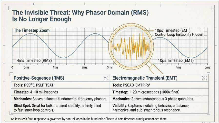
Tools: PSS®E, PSLF, TSAT, PowerFactory RMS. Typical timestep: 4–10 milliseconds. The network is represented as balanced positive-sequence phasors at fundamental frequency. Fast switching, harmonics, and unbalance are not represented. These models run large networks quickly, which is why they remain the backbone of planning studies.
Electromagnetic transient (EMT)
Tools: PSCAD/EMTDC, EMTP-RV, PowerFactory EMT, RSCAD. Typical timestep: 1–20 microseconds — roughly a thousand times finer. Instantaneous three-phase quantities are solved, so switching behaviour, unbalance, harmonics, DC offset, saturation and control-loop dynamics down to the current regulator are all represented.
An inverter's response to a fault is governed by control loops with bandwidths in the hundreds of hertz to low kilohertz. A 4 ms timestep cannot see them. That is the entire reason EMT models are required: the phenomena that caused the disturbances are invisible in the phasor domain.
Where EMT is specifically required:
- Weak grid and low-SCR stability assessment
- Subsynchronous resonance and subsynchronous control interaction
- Phase angle jump response
- Unbalanced fault response and negative-sequence current injection
- Harmonic interaction and control instability between adjacent plants
- Detailed ride-through verification against IEEE 2800 curves
- Series-compensated line applications
- Grid-forming behaviour and islanding
Where positive-sequence remains sufficient: bulk transient stability, large-area planning, most contingency screening.
Because the two must agree, cross-validation between the EMT and RMS models is now a formal deliverable in its own right — and often the item that exposes errors in both.
3. Model types: black box, white box, and real code
OEMs face a genuine tension. The model must be detailed enough to reproduce controller behaviour, but the controller is the product. Three approaches manage that tension differently.
Black box (compiled, encrypted)
The control logic is implemented in the EMT tool, then compiled into a library and encrypted. Third parties can run the model, set parameters and view terminal quantities, but cannot inspect or extract the control code.
- Protects IP: strongly
- Fidelity: high, limited by the accuracy of the implementation
- Accepted by ISOs: yes, this is the standard commercial form
- Maintenance: must be rebuilt when firmware changes
This is what the overwhelming majority of OEM models are, and what most manufacturers should build.
White box (open source)
Control logic visible and editable. Rare in commercial practice — used internally, in research, or where a utility contractually demands full visibility.
- Protects IP: no
- Fidelity: high
- Use case: internal development, academic collaboration
Real code (firmware-derived)
The production controller source — typically C running on a DSP, sometimes with an FPGA layer — is converted into the EMT environment rather than re-implemented from block diagrams. The simulated controller executes the same logic as the physical controller.
- Protects IP: yes, when compiled and encrypted
- Fidelity: highest available in software
- Cost and effort: substantially higher
- Advantage: tracks firmware releases with much lower revalidation effort
- Requirement: sustained access to firmware source and the build toolchain
Real-code models are becoming the expectation in some markets and for some equipment classes. For most OEMs entering the space, a well-built black-box model is the correct first deliverable, with real-code conversion considered later if market pressure justifies it.
4. What a manufacturer-grade PSCAD model actually contains
"A PSCAD model" is not a single artefact. A model package that will survive ISO review has several layers, and OEMs consistently underestimate the ones below the surface.
4.1 Power stage
- Converter topology and switching representation — two-level, three-level, NPC, ANPC, modular multilevel as applicable
- Modulation scheme, carrier arrangement, dead time
- DC link capacitance, pre-charge circuit, DC bus operating window
- AC filter topology and component values, including damping
- Interface transformer: rating, vector group, impedance, X/R, tap range, and saturation characteristic where relevant
- Internal impedances between modules, cabinet and point of connection
- DC-side source or load representation — battery, PV array, wind generator, rectifier load — with its own dynamics
An important practical point: full switching representation is expensive to simulate. Many production models use an averaged or hybrid switching representation that reproduces terminal behaviour accurately at a manageable timestep. Whether that is acceptable depends on the study type, and the choice must be documented, not silently made.
4.2 Control system
This is where the effort concentrates.
- Phase-locked loop: structure, bandwidth, and behaviour under unbalanced and distorted supply
- Inner current regulator: reference frame, bandwidth, decoupling, anti-windup
- Outer loops: DC voltage, active power, reactive power, AC voltage, power factor
- Current limiting strategy and active/reactive priority under fault
- Negative-sequence current injection behaviour
- Ride-through logic: momentary cessation behaviour, blocking and de-blocking thresholds, recovery ramp rates
- Autonomous grid support functions: volt-VAR, volt-watt, frequency-watt
- Sample rates, computation delays, actuation delays, measurement filter time constants
- Start-up, synchronisation, soft-start, pre-charge, shutdown sequences
Delays and filter time constants deserve special mention. They are routinely omitted from OEM documentation and routinely decisive in weak-grid stability results. A model with correct gains and wrong delays will look right in a strong grid and be wrong where it matters.
4.3 Protection
Protection is not optional detail. It determines whether the model trips, and tripping behaviour is precisely what ISOs are trying to assess.
- AC and DC over/under voltage and over/under current, with pickup levels and time delays
- Over and under frequency
- Phase jump, RoCoF and vector shift protection, and whether these are user-defeatable
- Thermal, ground fault, insulation monitoring
- Anti-islanding scheme where applicable
PRC-029-1 recommends disabling phase-jump protection that trips unnecessarily during permissible phase angle excursions. A model that does not represent the protection cannot demonstrate compliance either way.
4.4 Plant controller interface
Most ISOs require that the model accept external setpoints in the way the real plant does. SPP's PSCAD model requirements, for example, specify that the plant power controller accept an external active power setpoint and a voltage setpoint, implement a settable voltage droop, and that the model initialise to the setpoints specified in the PPC. Communication latency and setpoint update rate must be represented.
4.5 Aggregation
A plant contains many inverters. Simulating each one individually is impractical. The model must support a documented aggregation approach — typically a single-unit equivalent scaled to plant rating, sometimes with a small number of representative units where diversity matters. The aggregation basis and its limitations belong in the documentation.
4.6 Numerical behaviour
The least visible layer, and the one that most often causes rejection.
- Timestep: models are generally expected to run at 10–20 µs. Some ISOs accept smaller timesteps where the penalty is not significant, but a model that only runs at 1 µs will be unwelcome in a large study case.
- Initialisation: the model must reach steady state cleanly from a flat start and initialise to the specified setpoints, without manual intervention.
- Snapshot capability: studies rely on saving and restoring a converged state. A model that cannot snapshot forces every run to re-initialise.
- Multi-instance: dozens of instances in one case, each with independent parameters and no shared-state collisions.
- Parallel and multi-core execution: required for large study cases.
- Compiler compatibility: typically Intel Fortran, against the PSCAD versions the ISO and the consultant are running.
4.7 Documentation and packaging
- Encrypted compiled library, installer, and licence file where used
- User manual: installation, parameters with ranges and units, control modes, aggregation guidance
- Parameter data sheet mapping model parameters to real product settings
- Validation report
- Model quality test conformance record
- Release note recording model version, firmware version modelled, and known limitations
5. Model quality testing: what reviewers actually run
Model quality tests exist because reviewers were receiving models that would not run. They are basic in concept and unforgiving in practice.
ERCOT introduced model quality test requirements effective May 2020, initially for PSS®E dynamic models, and requires MQT reports for all new and updated models — PSS®E and PSCAD. Since 2024, PGRR-109 has required IBRs to submit an as-built model alongside the quarterly stability assessment model and overlay the MQT plots before commissioning. ERCOT's NOGRR-245 updated voltage and frequency ride-through requirements to align with IEEE 2800, and ride-through capability must be demonstrated in models.
Typical test content across ISOs:
| Test | What it demonstrates |
|---|---|
| Flat start / no disturbance | Model initialises and holds steady state without drift or oscillation |
| Voltage step change | Reactive control response, damping, absence of instability |
| Active power reference step | Active control response and ramp behaviour |
| Balanced fault (LVRT) | Ride-through against the applicable voltage envelope, current injection during fault, recovery behaviour |
| Unbalanced fault | Negative-sequence response, phase current behaviour, no spurious tripping |
| High voltage (HVRT) | Ride-through of overvoltage excursions |
| Frequency excursion and RoCoF | Frequency ride-through and frequency-watt response; PRC-029-1 expects withstand of at least 5 Hz/s |
| Phase angle jump | Withstand of angle steps — IEEE 2800 and PRC-029-1 reference up to 25 degrees |
| Weak grid / low SCR | Stability at specified short-circuit ratios; SPP specifies SCR 2.5 tests, replaceable with the contingency SCR at the POI |
| EMT-to-RMS benchmarking | PSCAD and PSS®E responses agree within tolerance for the same disturbances |
A model that fails MQT is returned for retuning and resubmission. For an OEM, that means the customer's schedule slips and the OEM is visibly responsible.
6. Validation: the part that determines everything
A model that has not been validated against hardware is an assertion, not evidence. Validation is also, consistently, the item that determines whether a modelling project runs to schedule.
What is needed
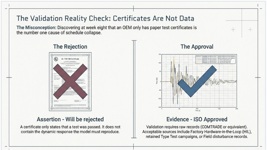
The distinction that matters most: test certificates are not validation data. A UL 1741 SB or IEC 61851 certificate states that a test was passed. It does not contain the waveform. Validation requires raw records — COMTRADE or equivalent — showing the measured response.
Required records typically include:
- Low and high voltage ride-through, balanced and unbalanced, across the applicable envelope
- Frequency ride-through and RoCoF events
- Phase angle jump
- Reference step responses: active power, reactive power, AC voltage, DC voltage
- Weak grid stability tests with the tested SCR stated
- Harmonic emission and power quality records
- Hardware-in-the-loop results, where available
- Field disturbance records from operating installations, where available
Sources of validation data
- Type test campaigns. UL 1741 SA/SB, IEEE 1547.1, IEC 61400-21, IEC 62116 and equivalents generate exactly the disturbance responses needed — but only if raw captures were retained. Many were not.
- Hardware-in-the-loop. The most efficient source. A real controller running against a simulated grid can produce any test case on demand.
- Factory test records. Useful for control response, usually not for ride-through.
- Field records. Highest credibility for post-event validation, but opportunistic.
When the data does not exist
This is common, particularly for products that were certified before EMT modelling became a commercial requirement. Options, in descending order of preference:
- Run a targeted HIL campaign against the specific test cases the model needs
- Run a supplementary laboratory campaign at a grid simulator facility
- Validate against a subset and document the unvalidated envelope explicitly
- Proceed on documented assumptions, accepting reduced defensibility under review
The last option is legitimate but should be a conscious decision. Every assumption belongs in an assumptions register reproduced in the validation report. Reviewers do not object to assumptions; they object to discovering them later.
7. The PSS®E companion model
Most OEMs asking for a PSCAD model actually need two models.
Transmission providers run planning studies in the phasor domain and detailed studies in EMT. Both need to reflect the same equipment, and the requirement to show they agree is now explicit — ERCOT's MQT includes benchmarking PSCAD against PSS®E, and NERC's EMT modelling work formalises cross-validation practice.
Two routes exist for the positive-sequence model:
Generic library models. The WECC/IEEE second-generation renewable energy models — REGC_A/B/C, REEC_A/B/C/D, REPC_A/B, and their equivalents — parameterised to represent the product. Fast, widely accepted, and adequate for many products. The limitation is real: generic models cannot represent behaviour their structure does not contain.
User-written models. A custom compiled dynamic model. Higher fidelity, higher effort, higher maintenance burden.
Whichever route is taken, developing the EMT and RMS models in parallel is materially more efficient than sequentially, because cross-validation failures usually indicate an error in one of them, and finding that error early is cheaper than finding it at submission.
8. Grid-forming: the emerging second requirement
Conventional inverters are grid-following: they synchronise to a measured voltage through a PLL and inject current. This works while the grid is strong. As system strength falls, PLL-based control approaches its stability limit.
Grid-forming control instead regulates voltage magnitude and angle directly, presenting as a voltage source behind an impedance. Grid-forming inverters can support islanded operation, contribute to system strength, and provide inertial response.
For OEMs, three implications:
- Tender requirements are shifting. Grid-forming capability is increasingly requested for BESS, microgrid and backup power applications, and is being specified in some interconnection requirements.
- Grid-forming models require different validation. The relevant tests are weak-grid and no-grid cases, black start, load steps in islanded operation, and parallel operation with other grid-forming units — not the standard grid-following test matrix.
- Dual-mode products need dual-mode models. If the product can operate in either mode, the model must represent both, including the transition.
Modelling a grid-forming mode is not a small increment on a grid-following model. Budget for it separately.
9. Schedule: what actually drives it
A manufacturer-grade PSCAD model for a single product, grid-following, black box, with a companion positive-sequence model, is realistically a 650 to 900 hour engagement. On a standard programme that is 18 to 24 weeks. Compressed with parallel workstreams and a dedicated team, 12 weeks is achievable. A project-specific model for one named study can be delivered in around 5 weeks.
What sets the position within that range is rarely engineering difficulty. It is:
- Documentation quality. Complete control block diagrams with gains, time constants and per-unit bases put a project at the fast end. Marketing datasheets put it at the slow end.
- Whether documentation matches shipping firmware. The most expensive discovery in this work is that the block diagrams describe a control structure that was superseded two firmware revisions ago.
- Validation data availability. Raw waveforms available: fast. Certificates only: add substantial time or a test campaign.
- OEM responsiveness. Query turnaround is the single largest schedule variable in practice. A 48-hour response cadence and a 10-day response cadence produce very different delivery dates from identical scopes.
- Number of variants. Each hardware variant and each firmware baseline is a separate modelling exercise, not a parameter change.
Accelerating delivery
Two techniques genuinely compress the critical path:
Interim model release. A numerically stable, functionally complete model can be issued before formal validation and packaging are complete. The customer begins preliminary study work weeks before formal release, under a clear limitation statement, and receives the validated model when it is ready. From the customer's perspective the schedule halves.
Parallel workstream execution. Power stage and control development run concurrently; documentation is drafted alongside validation rather than after it; the positive-sequence model is developed in parallel with the EMT model throughout.
10. Where these projects go wrong
Patterns that recur across OEM engagements.
Treating it as a documentation exercise. It is a development project with its own validation, version control and release management.
Underestimating numerical hardening. A model that reproduces every waveform correctly but cannot snapshot, cannot run multi-instance, or requires a 1 µs timestep will be rejected. This layer routinely consumes 15 to 20 percent of total effort.
Certificates instead of waveforms. Discovering at week eight that no raw records exist.
No version control. A model released without recording which firmware version it represents becomes unmaintainable within two release cycles.
No maintenance plan. Every firmware release touching grid-facing control or protection invalidates the released model. An OEM with a two-year-old model and four firmware releases since has a model that misrepresents its own product — a genuine liability once customers have submitted it to regulators.
Modelling one variant and issuing it for all. Different hardware ratings and different firmware baselines require separate models or, at minimum, a documented validity statement.
Firmware and modelling teams not talking. The model is derived from control logic. If the firmware team is not directly engaged, the model is being built from documentation, and documentation drifts.
11. Maintenance and versioning
The deliverable is not one-time. A sustainable arrangement includes:
- A defined trigger for revalidation — typically any firmware change affecting control, protection or grid-facing behaviour
- Version numbering that ties model version to firmware version explicitly
- A release note recording what changed and what was revalidated
- Migration across PSCAD major versions as they are released
- First-line support for customers and their consultants running the model
Per-release revalidation of a black-box model is typically 40 to 80 hours. An annual retainer is usually more economical than release-by-release engagement, and it avoids the situation where a customer needs an updated model faster than a procurement cycle can produce one.
Frequently Asked Questions
General
Do we actually need a PSCAD model, or can we send a PSS®E model?
For inverter-based resources, both are generally required. Positive-sequence models cannot represent fast inner-loop control behaviour, which is exactly what the EMT requirement exists to capture. Some model quality tests can be completed in PSS®E or TSAT, with PSCAD required for phase angle jump tests and specific EMT investigations, but for an OEM building a product-level model package the practical answer is both.
Who is responsible for producing the model — the OEM or the developer?
Contractually, model submission obligations fall on the Generator Owner or interconnection customer. Practically, the OEM must supply the equipment model, because only the OEM has the control system information. Those obligations flow back to the OEM through supply contracts, and OEMs that cannot supply a model find it in their commercial terms eventually.
Will we have to expose our control IP?
No. The standard commercial form is a black-box model: compiled and encrypted, executable but not inspectable. Your control logic is not disclosed to customers, consultants or ISOs. The modelling engineer needs access under NDA; the released model does not expose it.
Our product is a load, not a generator. Does this apply?
Increasingly, yes. Large power-electronic loads — data centres, electrolysers, industrial rectifiers — are drawing regulatory attention following large-scale load loss events. Ride-through and modelling expectations are extending to large flexible loads. If your product is bi-directional, or certified for export capability even if export is not currently enabled, treat it as an IBR.
How much does a manufacturer-grade PSCAD model cost?
Engagements for OEM product-level models typically run into six figures for a full package including validation, packaging, documentation and a companion positive-sequence model. Project-specific single-study models are considerably less. The largest cost variable is validation data availability, not modelling effort.
Technical
What timestep should the model run at?
Generally 10 to 20 microseconds. Models requiring smaller timesteps may be acceptable where the penalty is not significant, but a model that only runs stably at 1 µs will be problematic in large study cases and may be rejected.
Can we use an averaged switching model rather than full switching?
Often yes, and it is common practice for runtime reasons. What matters is that terminal behaviour is accurate for the study types the model will be used in, and that the representation is documented. Some studies — harmonic interaction, certain SSR investigations — require detailed switching.
Does the model need to include the plant controller?
It needs to interface with one. ISOs typically require that the model accept external active power and voltage setpoints, implement settable voltage droop, and initialise to the specified setpoints. If you also supply the PPC, that layer needs modelling too.
What is multi-instance capability and why does it matter?
Study cases contain many instances of the same model, each with independent parameters. If the model uses shared or static state internally, instances interfere and results are wrong. Multi-instance capability is a standard model quality requirement and is not automatic — it must be designed in.
What does snapshot capability mean?
The ability to save a converged simulation state and restore it later. Studies rely on it heavily: without it, every run must re-initialise from flat start, which is slow and, in some cases, fails. It is a standard requirement.
How do we handle aggregation from one inverter to a full plant?
Most models are supplied as a single-unit equivalent that scales to plant rating, with the aggregation basis and its limitations documented. Where inverter diversity within the plant materially affects results, a small number of representative units may be needed. The aggregation approach should be stated explicitly, not left for the study engineer to infer.
What about negative-sequence current injection?
It must be represented. Unbalanced fault response is a core EMT test case, and behaviour under unbalance is one of the principal reasons EMT models are required at all.
Do control delays really matter that much?
Yes. Computation delay, actuation delay and measurement filter time constants have a strong influence on stability margin at low short-circuit ratio. A model with correct gains and omitted delays will match test data in a strong grid and give wrong answers in the weak-grid cases the study exists to investigate.
How do EMT and PSS®E models get cross-validated?
The same disturbance set is run in both tools and the responses overlaid. Agreement is assessed against tolerance criteria. Divergence usually indicates an error in one model, occasionally a legitimate domain difference that must be documented. ERCOT's model quality tests include PSCAD-versus-PSS®E benchmarking.
Data and validation
What data do you need from us to build the model?
Broadly: single-line diagram and topology; converter topology, switching frequency and modulation scheme; DC link and filter parameters; interface transformer data; complete control block diagrams with gains, time constants and per-unit bases; current limiting and priority logic; ride-through logic; protection settings with pickup levels and time delays; sample rates and delays; the full user-adjustable parameter list with ranges; and validation waveform records.
We only have test certificates, not raw waveforms. Is that a problem?
Yes, and it is the most common schedule risk in this work. A certificate confirms a test was passed; it does not contain the response the model must reproduce. If raw records were not retained, the options are a targeted HIL campaign, a supplementary lab campaign, or validation against a reduced envelope with the unvalidated region documented.
Can you build a model without our firmware source code?
Yes. A black-box model built from control block diagrams is standard practice and does not require source access. Firmware source is only needed for a real-code model.
What if our documentation does not match our shipping firmware?
This is common and needs to surface early. The remedy is a working session between the modelling engineer and your firmware team to reconcile the two before implementation begins. Discovering the mismatch during validation is far more expensive.
How is the model validated if the product is not yet in production?
Against hardware-in-the-loop results using the actual controller, and against prototype test records. The model is then revalidated against production type test data once available. The interim model should carry an explicit limitation statement.
Regulatory
What is PRC-029-1 and does it affect us as an OEM?
PRC-029-1 establishes performance-based frequency and voltage ride-through requirements for inverter-based resources, adopting the IEEE 2800-2022 curves. It becomes effective 1 October 2026 for BES facilities and 1 January 2027 for non-BES facilities. The obligation sits with the Generator Owner, but demonstrating compliance requires equipment that performs correctly and models that show it — both of which come from the OEM.
Does IEEE 2800 apply to our product?
IEEE 2800-2022 sets interconnection requirements for IBRs connected at transmission level. It is increasingly adopted by reference into ISO requirements — ERCOT's NOGRR-245 aligned its ride-through requirements with it. Whether it applies directly depends on connection voltage and jurisdiction, but designing and modelling to it is the safe default for equipment sold into North America.
What does a PSCAD model have to do with ride-through compliance?
PRC-029-1 is performance-based and assessed against actual behaviour during events, but dynamic modelling supports the design evaluation, and a settings review alone is a weaker compliance basis than EMT simulation. For OEMs, the model is also how customers verify before commissioning that the equipment will comply.
Do different ISOs have different requirements?
Yes. ERCOT, CAISO, MISO, PJM, SPP and NYISO each maintain their own EMT model requirements and acceptance criteria, and they differ in detail — timestep tolerance, required test cases, SCR levels, submission format. ERCOT's are generally the most demanding, which is why building to ERCOT criteria is a reasonable default for a product-level model intended for multiple markets.
How often do models need to be updated?
Whenever firmware changes affect grid-facing control or protection. ERCOT additionally requires parameter verification and model updates on a defined cadence, including within 30 days of settings changes and periodic refresh cycles. Treat the model as a versioned product artefact tied to firmware releases.
Commercial and process
How long does it take?
A full product-grade package: 18 to 24 weeks on a standard programme, or around 12 weeks on a compressed programme with parallel workstreams and a dedicated team. A project-specific model for one named study: around 5 weeks. Add time for grid-forming modes and additional platforms.
Can we get something faster for a customer who is stuck in a queue?
Yes, through two mechanisms. A project-specific model scoped to one named study can be delivered in weeks rather than months. And on a full engagement, an interim model can be released before formal validation completes, so the customer's study work starts substantially earlier than the formal release date.
Should we build the model in-house?
Some large OEMs do, and it is the right answer where inverter modelling is a permanent core capability. It requires EMT expertise, familiarity with each ISO's acceptance criteria, and ongoing maintenance capacity. For manufacturers entering the grid-connected market — or expanding into it from an adjacent product line — an external specialist is usually faster and cheaper for the first model, with knowledge transfer built into the engagement if in-housing is the long-term intent.
What do we get at the end?
An encrypted compiled PSCAD model package with installer; an example workspace with test cases pre-built; a user manual; a parameter data sheet mapping model parameters to product settings; a validation report with an assumptions register; a model quality test conformance record; a companion positive-sequence model package where in scope; and a release note tying the model version to a firmware version.
Who owns the model?
Ownership and the licence granted to your customers are contractual. The typical arrangement: the OEM owns the delivered model and licenses it to customers; the modelling firm retains rights in its underlying methodology, libraries and tooling; the OEM retains all rights in its control system and firmware.
Who owns the model?
Ownership and the licence granted to your customers are contractual. The typical arrangement: the OEM owns the delivered model and licenses it to customers; the modelling firm retains rights in its underlying methodology, libraries and tooling; the OEM retains all rights in its control system and firmware.
Working with Keentel Engineering
Keentel Engineering provides power systems engineering and NERC compliance services to utilities, developers, EPCs, OEMs and public agencies across the United States. Our modelling practice covers:
- PSCAD EMT model development for inverter-based resources, including black-box packaging and encryption
- PSS®E, PSLF, TSAT and PowerFactory dynamic model development and user-defined models
- EMT-to-RMS cross-validation and benchmarking
- ERCOT Model Quality Test preparation and submission support
- PRC-029-1 applicability assessment and ride-through design evaluation
- MOD-026 / MOD-027 model verification and parameter verification reporting
- Weak-grid, low-SCR and subsynchronous studies
- Model maintenance and revalidation across firmware and software releases
If you manufacture grid-connected power electronics and need a model your customers can submit, we can scope it from your existing documentation and tell you what is missing before you commit to anything.
Keentel Engineering
Head Office: 400 N Ashley Dr STE #2600, Tampa, FL 33602 — (813) 389-7871
Austin: 5900 Balcones Drive STE 100, Austin, TX 78731 — (512) 591-0752
Sacramento: 1401 21st St Ste R, Sacramento, CA 95811 — (916) 913-4524
Baltimore: 306 W Redwood St STE 200, Baltimore, MD 21201 — (410) 225-2181
contact@keentelengineering.com | keentelengineering.com
This article is provided for general information and does not constitute legal, regulatory or engineering advice for any specific project. Regulatory effective dates, thresholds and ISO requirements are subject to change; verify current requirements with the applicable authority. Information reflects
Keentel Engineering's understanding at the date of publication.

About the Author:
Sandip "Sonny" R. Patel, P.E.
IEEE Senior Member · Founder & CEO, Keentel Engineering
In 1995, Sonny Patel earned his Electrical Engineering degree from the University of Illinois. But degrees don't build legacies — action does.
For three decades, he has worked the power industry from every side of the table: 16 years as a utility engineer at Exelon/Commonwealth Edison; generation leadership across hydroelectric, industrial steam turbine, and a 9 GW renewable fleet; NERC Regional Entity Senior Compliance Engineer and Audit Team Lead, auditing some of the nation's largest utilities; and testing and commissioning lead on equipment up to 765 kV — the very top of the North American grid.Utility. Generator. Regulator. Consultant. Few engineers have seen all four seats. Fewer still have sat in them.
His experience spans nuclear, hydro, conventional generation, renewables, oil and gas, mining — and today's data centers, where he is authoring a three-book series on data center design. He is a Licensed Professional Engineer in six states and a Licensed Electrical Contractor in Florida (Unlimited EC) — he doesn't just design the work; he's qualified to stand behind its execution.Today, as Founder and CEO of Keentel Engineering, Sonny leads a nationwide team of engineers delivering substation design, power system studies, NERC compliance, and commissioning — done right, coast to coast.Three decades. Every side of the table. One standard: accountable engineering.
Services

Let's Discuss Your Project
Let's book a call to discuss your electrical engineering project that we can help you with.
About the Author:
Sandip "Sonny" R. Patel, P.E.
IEEE Senior Member · Founder & CEO, Keentel Engineering
In 1995, Sonny Patel earned his Electrical Engineering degree from the University of Illinois. But degrees don't build legacies — action does.
For three decades, he has worked the power industry from every side of the table: 16 years as a utility engineer at Exelon/Commonwealth Edison; generation leadership across hydroelectric, industrial steam turbine, and a 9 GW renewable fleet; NERC Regional Entity Senior Compliance Engineer and Audit Team Lead, auditing some of the nation's largest utilities; and testing and commissioning lead on equipment up to 765 kV — the very top of the North American grid.
Utility. Generator. Regulator. Consultant. Few engineers have seen all four seats. Fewer still have sat in them.
His experience spans nuclear, hydro, conventional generation, renewables, oil and gas, mining — and today's data centers, where he is authoring a three-book series on data center design. He is a Licensed Professional Engineer in six states and a Licensed Electrical Contractor in Florida (Unlimited EC) — he doesn't just design the work; he's qualified to stand behind its execution.
Today, as Founder and CEO of Keentel Engineering, Sonny leads a nationwide team of engineers delivering substation design, power system studies, NERC compliance, and commissioning — done right, coast to coast.Three decades. Every side of the table. One standard: accountable engineering.
Leave a Comment
Thank you for contacting us.
We will get back to you as soon as possible.
We will get back to you as soon as possible.
Oops, there was an error sending your message.
Please try again later.
Please try again later.
Related Posts

By Team 2 Dexora
•
October 20, 2026
Explore grounding system testing with Keentel Engineering. Learn IEEE 80/81 methods, soil resistivity, ground resistance, and touch and step voltage safety.

By SANDIP R PATEL
•
October 13, 2026
Plan data center capacity with land screening, MW-per-acre estimates, grid power availability and interconnection feasibility studies from Keentel Engineering.

By SANDIP R PATEL
•
October 11, 2026
Learn which fault produces the highest current at a bus, why SLG faults can exceed three-phase faults, and how symmetrical components determine fault duty.

By SANDIP R PATEL
•
October 11, 2026
Learn why zero-sequence current pulsates in the dq0 frame, how Park's transformation works, and how inverter controls handle unbalance and ground faults.

By SANDIP R PATEL
•
October 11, 2026
Explore grid inertia, RoCoF and frequency response, with swing equation calculations, frequency nadir analysis and US power system simulation examples.

By SANDIP R PATEL
•
October 11, 2026
Learn transient stability analysis, swing equation, equal-area criterion and critical clearing time with a 345 kV worked example and NERC TPL-001 guidance.

By SANDIP R PATEL
•
October 11, 2026
Learn why inverter controls become unstable in weak grids, how PLL bandwidth and SCR affect stability, and how PSCAD EMT studies identify and mitigate oscillations.

By SANDIP R PATEL
•
October 11, 2026
Learn how STATCOMs improve voltage stability and prevent FIDVR. Explore reactive power sizing, delayed fault clearing, NERC criteria and 138 kV simulation results.

By SANDIP R PATEL
•
October 10, 2026
Learn BESS DC sizing with power, energy, current and C-rate calculations, battery losses, degradation and a 100 MW/400 MWh utility-scale example.





