
A Coordinated Electric System Interconnection Review—the utility’s deep-dive on technical and cost impacts of your project.
Challenge: Frequent false tripping using conventional electromechanical relays
Solution: SEL-487E integration with multi-terminal differential protection and dynamic inrush restraint
Result: 90% reduction in false trips, saving over $250,000 in downtime
Substation Electrical Design:
The 30% / 60% / 90% / IFC
jun 23, 2026 | Blog
A practitioner’s guide to milestone-based engineering, drawing maturity, multidiscipline coordination, and construction-ready deliverables written for developers, utilities, EPCs, and large-load owners.
Executive Summary
Substations are not drawn in a single pass. A safe, constructible, code-compliant substation emerges through a disciplined sequence of design milestones commonly expressed as 30%, 60%, 90%, and Issued for Construction (IFC) in which the design matures from concept to a sealed, build-ready package. Each milestone has a distinct purpose: the 30% package establishes intent and confirms the station fits the system; the 60% package proves the disciplines coordinate and supports a credible construction estimate; the 90% package is fully checked and ready for final issue; and the IFC package is the sealed, comprehensive set a contractor builds from.
This paper explains what actually belongs in each substation electrical package, how the design develops between milestones, what the licensed Professional Engineer’s seal means and when it is applied, and which industry standards govern the work. It closes with five anonymized case studies drawn from real project patterns and an in-depth FAQ. Throughout, Keentel Engineering’s position is consistent: grid interconnection is a first-order design input, not a downstream formality — and the milestone process is where that principle is enforced.
Why this matters
Most substation cost and schedule risk is created or avoided in the gap between 30% and 60%. Decisions made at concept (voltage, fault duty assumptions, footprint, equipment ratings) propagate through every later drawing. A rigorous milestone discipline catches the expensive problems while they are still lines on a drawing, not steel in the yard.
1. Why Substations Are Designed in Milestones
A substation is a tightly coupled system of electrical, civil, structural, and protection-and-control elements occupying a confined footprint. The bus has to clear the steel; the steel has to land on foundations; the foundations have to miss the ground grid and the duct bank; the relays have to match the CT ratios; and all of it has to satisfy the interconnecting utility, the applicable codes, and the owner’s budget. No engineer designs all of that correctly in one attempt.
The milestone model solves this by making the design reviewable at defined levels of completeness. At each stage the owner, the utility, and the reviewing engineers can confirm the design is heading the right direction before more hours and more committed procurement are spent. The percentages are not a measure of effort spent; they describe how complete and how firm the documentation is, and what decisions are locked versus still open.
1.1 Interconnection-First: the input that shapes every milestone
For grid-connected substations utility-scale solar and storage, wind, and large new loads such as data centers the single most consequential external input is the interconnection study process. The System Impact Study (SIS) and the subsequent facilities study establish the point-of-interconnection (POI) requirements, the available and post-project fault duties, metering and protection requirements, and the schedule for utility-side work.
Preliminary design values are exactly that preliminary. They are explicitly written to be validated and updated during detail engineering once the interconnection fault model is finalized. A design that treats interconnection as an afterthought routinely discovers, at 60%, that equipment selected at 30% is now under-rated for the confirmed fault current. Treating the interconnection as a first-order driver of the 30% package is the discipline that keeps the 60% package from becoming a redesign.
Keentel insight
The cleanest projects we see are the ones where the 30% one-line is drawn against the interconnection requirements, not against an assumed feeder. When the SIS confirms duties at 60%, the only change should be a refinement of margins not a wholesale re-rating of breakers, bus, and grounding.
2. The 30% Design Package Concept & Preliminary
Purpose: demonstrate understanding of the project and the system it connects to, confirm the station concept is viable, and define what the finished design will contain. The 30% package is where the owner and reviewers decide whether the design is meeting expectations, whether a course correction is needed, or whether project requirements should be re-evaluated while changes are still cheap.
2.1 Key engineering tasks at 30%
- Preliminary electrical load and capacity basis — station ratings derived from the generation or load to be served and the POI voltage.
- Voltage selection and major equipment sizing transformer MVA and ratio, primary and secondary voltages, basic insulation level (BIL), preliminary continuous current and interrupting ratings.
- Preliminary fault-duty basis first-pass three-phase and line-to-ground fault currents (often from the interconnection request and prior studies), explicitly flagged for validation against the SIS / fault model.
- Initial single-line diagram (SLD) the spine of the entire design: sources, bus arrangement, transformer, breakers, switches, instrument transformers, surge arresters, and metering.
- Design criteria basis the controlling standards, clearances, and parameters captured in a design criteria document so every later drawing inherits a single source of truth.
2.2 Typical 30% substation deliverables
For a collector or interconnection substation, a 30% electrical package typically contains:
- Preliminary power one-line diagram (high-level view).
- Preliminary general arrangement / equipment layout plan and preliminary site plan.
- Preliminary cable-routing and duct-bank concept.
- Design criteria document — system parameters (nominal/maximum voltage, BIL, continuous current, fault duties), electrical clearances, grounding basis, lightning-protection basis, AC station-service concept.
- List identifying major electrical equipment and components.
- Identification of long-lead procurement items (the long-lead clock starts here).
- A preliminary construction cost estimate and a complete list of the drawings, specifications, and calculations the final package will contain.
The 30% deliverable list is itself a deliverable
A defining feature of a good 30% package is that it tells the owner what every later package will contain — the full drawing index, the calculation list, and the specification list. This is also where drawing numbers are reserved so they appear consistently from 60% onward. If a reviewer cannot see the shape of the finished design at 30%, the package is not really at 30%.
2.3 What is deliberately NOT finished at 30%
Schematic and wiring diagrams, detailed
grounding-grid calculations, foundation design, and final equipment specifications are intentionally immature at 30%. The fault duties are not yet validated. Committing to detailed schematics before the fault model is confirmed wastes hours that the 60% phase will erase.
3. The 60% Design Package Detailed Design & Multidiscipline Coordination
Purpose: the 60% package is the primary coordination milestone. It carries enough detail that a construction estimator can develop a credible class estimate, and that reviewers can see how the design meets the project intent. Where information is intentionally omitted, a placeholder and an explanation take its place rather than a silent gap.
3.1 Key engineering tasks at 60%
- Finalize major-equipment specifications transformer, switchgear/breakers, switches, instrument transformers, surge arresters now reconciled against validated fault duties and continuous ratings.
- Develop the protection-and-control (P&C) scheme protection one-lines with ANSI device function numbers, relay selection, CT/VT ratios, and the trip/control philosophy.
- Detailed cable sizing and routing ampacity with derating, conduit fill, cable-tray and duct-bank layouts.
- Preliminary grounding-grid and lightning-protection studies step/touch-voltage analysis and direct-stroke shielding analysis carried to a reviewable result.
- Multidiscipline clash review electrical, structural, and civil reconciled spatially, increasingly through a coordinated 3D model, so bus, steel, foundations, grounding, and duct banks physically coexist.
3.2 Typical 60% substation deliverables
Building on the 30% set, the 60% package typically adds:
- Updated, detailed one-line diagram(s) and protection one-line(s).
- Detailed equipment layout, elevations, and sections.
- Schematic and wiring diagrams (relaying, control, AC/DC station service).
- Preliminary grounding plan and lightning-protection layout with supporting calculations.
- Conduit/cable schedules, conduit routing, and cable-tray/rack layouts.
- Near-final equipment schedules and an equipment label schedule.
- Construction specifications approaching final form (organized to the CSI MasterFormat structure), and final procurement specifications for long-lead items so orders can be placed.
Reviewers should be able to develop a Class 2-level construction estimate (per AACE International’s cost-estimate classification) from a complete 60% set — which is why a draft of every sheet, specification, and calculation is expected, even if some carry placeholders.
Keentel insight
60% is where projects are won or lost on coordination. The most common avoidable rework we see is a grounding grid and a foundation/duct-bank layout designed in isolation, then colliding. We run the clash review against a single coordinated model precisely so the conflict shows up as a redline at 60%, not as a field change at construction.
4. The 90% Design Package Checked & Review-Ready
Purpose: the 90% package is fully checked and essentially ready for final issue and construction. The distinction from 60% is one of completeness and verification, not new scope. By 90% the engineering decisions are settled; the work is to confirm they are correct, internally consistent, and well drafted.
4.1 What checking actually means at 90%
Checking at 90% goes beyond technical adequacy. A proper 90% review addresses three layers:
- Technical adequacy calculations support the ratings shown; protection settings, grounding results, clearances, and equipment selections are verified against the design criteria and the validated study basis.
- Drafting-standard compliance sheets follow the drawing standard: borders, title blocks, drawing numbers, symbols, legends, and cross-references are correct and consistent.
- Editorial quality and workmanship errors, omissions, mismatched references, and inconsistencies between sheets are resolved. Each calculation carries its checklist and check record.
4.2 Typical 90% substation deliverables
- A complete, checked set of every drawing in the index one-lines, protection one-lines, general arrangement, elevations and sections, grounding plan and details, lightning protection, AC/DC station service, control-house layout, conduit/cable, and schedules.
- Final grounding-grid and lightning-protection calculations; final cable and conduit-fill calculations; arc-flash, load-flow, and short-circuit results as applicable.
- Construction specifications in final form; master submittal register aligned to the specifications.
- A design-requirements compliance record each requirement traced to where and how the design satisfies it (drawing/sheet, calculation, or test).
90% is a verification gate, not a design gate
If a reviewer finds genuinely new engineering at 90% — a changed transformer rating, a reworked protection scheme — that is a signal the 60% package was not truly at 60%. The 90% review should surface corrections and refinements, not surprises.
5. Issued for Construction (IFC) The Final Package
Purpose: IFC is the comprehensive, sealed package a contractor builds from. It incorporates all 90% review comments and carries no new, unreviewed information. By definition, nothing should appear at IFC that the owner and reviewers have not already seen it is the clean, final, releasable expression of the design.
5.1 What IFC contains
- The complete, finalized, and sealed construction drawing set.
- Foundation and grounding plans, final protection-and-control schematics, conduit/cable routing details, and the bill of materials (BOM).
- Final specifications and the procurement/submittal documentation needed to build and commission the station.
- All 90% comments dispositioned and incorporated; drawings carry the IFC revision and the engineer’s seal as required.
5.2 IFC is a status, not the end of engineering
Issuing for construction does not freeze a project in amber. Field conditions, vendor-certified equipment dimensions, and requests for information (RFIs) generate revisions. These are handled through controlled revisions to the IFC set — each change tracked, re-checked, and re-issued — rather than informal markups. The engineering rigor that produced the IFC package is the same rigor that governs every revision after it.
The 100% / record-set relationship
Some owners use a 100% or “final” designation that should contain no information not already reviewed at 90% — it simply incorporates final comments and adds the required professional seals. After construction, the design is updated to an as-built / record set reflecting what was actually installed. IFC, 100%, and as-built are points on the same continuous chain of custody for the design.
Deliverable maturity at a glance
The same document matures across milestones rather than appearing all at once. A representative progression for core substation electrical deliverables:
| Deliverable | 30% | 60% | 90% / IFC |
|---|---|---|---|
| Power one-line diagram | Anne | Detailed | Final / sealed |
| Protection one-line & P&C | Concept / device list | Scheme + settings basis | Final schematics / sealed |
| General arrangement, elevations, sections | Preliminary layout | Detailed | Final / sealed |
| Grounding grid & lightning protection | Design basis (IEEE 80/998) | Preliminary study | Final calc / sealed |
| Cable & conduit schedules | Routing concept | Detailed sizing | Final / sealed |
| Major-equipment specifications | Equipment list | Near-final spec | Issued for procurement |
| Construction cost estimate | Preliminary | Class 2-capable set | — |
| Bill of materials (BOM) | — | Developing | Final |
This is a representative pattern, not a contractual list the exact deliverable set is defined per project by the owner’s scope of work and the interconnecting utility’s requirements.
6. The Licensed Professional Engineer’s Seal
Construction-level substation drawings carry the seal and signature of a licensed Professional Engineer (P.E.). The seal is not a formality or a logo — it is a legal attestation that a qualified, licensed engineer prepared the work, or directly supervised its preparation, under what licensing law calls “responsible charge,” and takes professional responsibility for it.
6.1 What the seal means
- Responsible charge The sealing engineer exercised direct control and personal supervision of the engineering work not a rubber stamp of someone else’s drawings.
- Jurisdiction Engineering licensure is granted by individual state boards. The engineer who seals must hold a current license in the state (jurisdiction) where the project is located, regardless of where the firm is based.
- Accountability The seal ties the work to a named, licensed individual who is professionally and legally accountable for it. Permitting authorities, owners, and utilities rely on it as the mark of a constructible, code-aware design.
6.2 When the seal is applied
Sealing generally occurs at final issue IFC and/or 100% once the design is checked and complete. Interim packages (30%, 60%) are typically marked PRELIMINARY or NOT FOR CONSTRUCTION and are not sealed for construction, because they are explicitly subject to change. Some jurisdictions and owners require preliminary submittals to be identified as preliminary and signed accordingly; the controlling rule is always the state board’s and the owner’s requirements for that project.
Plain-language summary
A sealed drawing says: a licensed engineer, accountable under that state’s law, stands behind this design as ready to build. That is why IFC drawings are sealed and 30% drawings are not — and why the engineer must be licensed where the substation will actually be built.
7. The Standards Framework Behind Each Milestone
Substation design is governed by a layered framework of codes and consensus standards. A practical distinction matters here: codes (such as the National Electrical Safety Code and the National Electrical Code) are adopted into law by jurisdictions and are mandatory where adopted, while most IEEE documents are consensus guides and recommended practices that become binding when a regulator, utility specification, or contract incorporates them. Engineers treat the relevant IEEE standards as authoritative practice; their legal force comes from adoption, not from the standard itself.
7.1 Grounding and personnel safety
- IEEE Std 80 Guide for Safety in AC Substation Grounding: soil modeling and tolerable step/touch-voltage and grid-current design.
- IEEE Std 81 measuring earth resistivity and ground impedance (e.g., Wenner four-pin testing) to validate the grid model against real soil.
- IEEE Std 837 qualifying permanent grounding connections (exothermic welds, compression connectors).
7.2 Protection, automation, and control
- IEEE Std C37.2 standard device function numbers (e.g., 50/51 overcurrent, 87 differential) used on protection one-lines.
- IEEE Std C37.1 SCADA and automation systems.
- IEEE Std 1815 (DNP3) power-system communications protocol for grid automation.
- IEEE Std 1686 cyber-security capabilities for intelligent electronic devices (IEDs).
7.3 Physical design, equipment, and site
- IEEE Std 605
design of rigid-bus structures (clearances, mechanical loading, ampacity).
- IEEE C57 series power transformers, regulators, and instrument transformers (CTs/VTs).
- IEEE Std C37.122 gas-insulated substations (GIS).
- IEEE Std 69 seismic design of substations.
- IEEE Std 525
design and installation of cable systems (tray, ampacity derating, pull tension).
- IEEE Std 998 direct-stroke shielding / lightning protection (e.g., rolling-sphere and fixed-angle methods).
- IEEE Std 1127 (with IEEE Std 980) environmentally compatible substations: oil containment, acoustic limits, community integration.
- IEEE Std 1402 & IEEE Std 1264
physical/electronic security and animal/wildlife mitigation.
- ANSI C37.32, NESC, NEC, NFPA, RUS Bulletin 1724E-300 clearances and spacing, code-level safety requirements, fire and life safety, and the standard design-guide framework for substations.
A note on accuracy
It is common, but imprecise, to call IEEE 80 a “law” or a “mandate.” IEEE 80 is a consensus guide. It becomes enforceable when a utility, regulator, or contract requires it — which most do. Keentel states this distinction plainly because owners deserve to understand what is legally binding versus authoritative best practice.
8. Keentel Engineering’s Substation Electrical Design Services
Keentel Engineering provides full-lifecycle substation electrical design from interconnection-driven concept through sealed Issued-for-Construction packages for utility-scale renewables and storage, large new loads including data centers, utility and industrial substations, and transmission and switching stations. We engineer the milestone process itself, not just the drawings, so owners get predictable packages, defensible decisions, and a construction set that builds cleanly.
8.1 What we deliver
- Single-line and protection one-line development
the backbone of the design, drawn against interconnection requirements from day one.
- Physical design
general arrangement, equipment layout, elevations and sections, bus and clearance design (ANSI C37.32 / NESC).
- Grounding and lightning protection
IEEE 80 grounding-grid design and step/touch-voltage analysis; IEEE 998 direct-stroke shielding.
- Protection & control
relaying schemes, schematics and wiring, CT/VT sizing, and control-house layout.
- Power system studies
short-circuit, load-flow, coordination, and arc-flash to validate ratings and settings.
- Interconnection (POI) engineering
aligning the substation design with the SIS/facilities study and the utility’s requirements.
- Sealed deliverables 30%, 60%, 90%, and IFC packages, with P.E.-sealed construction drawing.
8.2 Why owners work with Keentel
- Interconnection-first engineering.
We treat the POI as a design driver, so the 60% package refines the concept instead of rebuilding it.
- Milestone discipline.
Defined, reviewable packages with no surprises 90% is a verification gate, IFC carries nothing new.
- Coordination rigor.
Clash review against a coordinated model so conflicts surface as redlines, not field changes.
- Standards fluency. Clear about what is code, what is consensus practice, and what the project actually requires.
Engage Keentel
Whether you are starting a 30% concept, recovering a stalled 60% package, or need a sealed IFC set on a deadline, Keentel can lead the design or step in mid-stream. Reach us at keentel.com — offices in Tampa, FL and Austin, TX.
9. Case Studies
The following case studies are composites drawn from real project patterns. All client names, locations, project identifiers, and proprietary details have been removed; figures are illustrative and rounded. They are presented to show how the milestone progression behaves on real work, not to describe any single identifiable project.
Case Study 1 Solar-plus-storage collector substation: the fault-duty correction
Context
A roughly 50 MW PV facility with battery storage required a collector substation stepping 34.5 kV collection up to a sub-transmission POI, with collector-feeder breakers, a step-up transformer, high-side breaker, disconnects, instrument transformers, and revenue metering.
Challenge
The 30% package was built on interconnection-request fault estimates. When the System Impact Study returned, the confirmed line-to-ground and three-phase duties were higher than the preliminary basis, pushing the bus-design and ground-grid fault currents up.
How the milestones handled it
Because the 30% one-line and equipment list were drawn against the interconnection requirements with documented margins, the 60% phase absorbed the higher duties as a refinement: equipment interrupting ratings and momentary withstand were re-checked, the ground-grid design current was updated under IEEE 80, and bus mechanical design was re-verified. No major equipment had to be re-selected.
Outcome
The 60% set supported a credible construction estimate; 90% checking confirmed the grounding and clearance results; IFC issued on schedule with sealed drawings. The correction cost drawing hours, not procurement.
Case Study 2 Hyperscale data-center load interconnection: procurement on the critical path
Context
A large new data-center load required a step-down substation from a transmission-class POI to medium-voltage distribution within the campus, on an aggressive energization deadline.
Challenge
The large power transformers and high-voltage breakers had procurement lead times far exceeding the design schedule. If the order waited for a finished design, energization would slip by quarters.
How the milestones handled it
Long-lead items were identified at 30%. Final procurement specifications for the transformers and breakers were completed at 60% ahead of the rest of the set so orders were placed while detailed design continued. The remaining drawings matured to 90% and IFC around the confirmed equipment dimensions.
Outcome
Decoupling long-lead procurement from full design completion protected the energization date. Vendor-certified dimensions fed the foundation and bus design before IFC, avoiding field rework.
Case Study 3 Brownfield distribution-substation rebuild: designing around a live bus
Context
An aging utility distribution substation required replacement of major equipment while continuing to serve load through portions of the existing yard.
Challenge
The station could not be fully de-energized. Construction had to proceed in stages, each requiring its own safe clearances, temporary protection, and outage windows.
How the milestones handled it
The 30% concept established a phased construction sequence as a design constraint, not an afterthought. The 60% package coordinated demolition and new-work drawings against the live equipment and the existing ground grid. The design was issued for construction as sequenced IFC packages aligned to the outage windows rather than a single release.
Outcome
Staged IFC issuance let the contractor build in step with available outages while load stayed served, with clearances and grounding verified for each phase.
Case Study 4 Wind-collector repowering: re-using steel, re-checking the grid
Context
A repowering effort updated the generation feeding an existing collector substation, with the owner seeking to reuse existing structures and foundations where possible.
Challenge
Updated generation changed the fault contribution and collector configuration. Reusing existing steel and foundations was attractive but could not be assumed safe without verification.
How the milestones handled it
At 30%, existing drawings were inventoried and the reuse-versus-replace question was framed explicitly. At 60%, the ground grid was re-evaluated under the revised fault current per IEEE 80, and bus/structure loading was re-checked; some reuse was confirmed, some elements were upgraded. 90% verified the mixed old/new design held together.
Outcome
Documented reuse where the math supported it and targeted upgrades where it did not capturing cost savings without compromising the grounding safety case.
Case Study 5 Industrial substation on a constrained, seismically active site
Context
A manufacturing facility needed a new substation stepping a sub-transmission supply down to plant medium-voltage, on a tight footprint in a region with meaningful seismic demand.
Challenge
Limited land pressured the layout, and seismic requirements raised structural and equipment-qualification concerns for rigid bus, insulators, and bushings. Arc-flash energy at the plant interface also needed control.
How the milestones handled it
The 30% phase evaluated a compact arrangement (including gas-insulated equipment per IEEE C37.122 as an option) against the footprint. 60% carried seismic design per IEEE 693 into structure and equipment selection, and the protection scheme was set to manage arc-flash incident energy. 90% checking reconciled the dense layout’s clearances and grounding; IFC issued sealed.
Outcome
A constructible station on a constrained site, with seismic qualification and arc-flash mitigation engineered in from concept rather than retrofitted at the end.
Frequently Asked Questions
What do 30%, 60%, 90%, and IFC actually mean?
They describe how complete and how firm the design documentation is — not how many hours have been spent. 30% confirms intent and concept; 60% is detailed and coordinated enough to estimate construction cost; 90% is fully checked and review-ready; IFC (Issued for Construction) is the sealed, final set a contractor builds from.
Is there always a 90% milestone? What about 100%?
No fixed rule — the milestone set is defined per project. Many owners use 30/60/90 then IFC; others add a 100%/final designation, or use 30/60/IFC. The principle is constant: a verification stage (90%) confirms a complete design before it is sealed and released. A 100% package should contain nothing not already reviewed at 90%.
What is the difference between 90% and IFC?
90% is a verification gate — the design is complete and being checked for technical adequacy, drafting compliance, and editorial quality. IFC incorporates the 90% comments and is the clean, sealed, releasable set. If genuinely new engineering appears at IFC, the earlier packages were mislabeled.
What specifically goes in a 30% substation electrical package?
Typically: a preliminary power one-line, preliminary general arrangement/site plan, cable-routing concepts, a design criteria document (voltages, BIL, fault-duty basis, clearances, grounding and lightning-protection basis, station-service concept), a major-equipment list, identification of long-lead items, a preliminary cost estimate, and the full index of drawings/specs/calculations the finished design will contain.
When are loads and fault currents finalized?
Preliminary values appear at 30%, drawn from the interconnection request and prior studies, and explicitly flagged for validation. They are confirmed against the System Impact Study and fault model during detailed (60%) engineering, when equipment ratings and the ground-grid design current are locked.
What is an AACE Class 2 estimate, and why is it tied to 60%?
AACE International classifies cost estimates by project definition and accuracy. A 60% design is expected to be complete enough — a draft of every sheet, spec, and calculation, with placeholders explained — that a construction estimator can produce a Class 2-level estimate. That is the practical test of whether a package is really at 60%.
Who seals the drawings, and what does the seal mean?
A licensed Professional Engineer (P.E.) who prepared the work or supervised it under responsible charge. The seal is a legal attestation that a qualified, accountable engineer stands behind the design. It is applied at final issue (IFC/100%), not on preliminary packages.
Does the P.E. have to be licensed in the project’s state?
Yes. Licensure is granted by individual state boards, and the sealing engineer must hold a current license in the jurisdiction where the project is located — regardless of where the firm or engineer is based. Many engineers hold licenses in multiple states for this reason.
Can a 30% or 60% package be sealed?
Interim packages are normally marked PRELIMINARY or NOT FOR CONSTRUCTION and are not sealed for construction, because they are expressly subject to change. Some jurisdictions require preliminary submittals to be identified and signed as preliminary. The controlling requirement is always the state board’s rules and the owner’s scope for that project.
Are IEEE standards mandatory — are they law?
Most IEEE substation documents are consensus guides and recommended practices, not laws. They become binding when a regulator, utility specification, or contract adopts them — which most utility work does. By contrast, the NESC and NEC are codes that jurisdictions adopt into law and are mandatory where adopted.
What is the difference between IEEE 80, the NESC, and the NEC?
IEEE 80 is the guide for designing a safe substation grounding grid (step/touch voltages, grid current). The NESC governs safety of electric supply and communication installations, including substation clearances. The NEC governs premises wiring. A substation design typically applies all three in their respective domains.
How does the interconnection process interact with the milestones?
Heavily. The System Impact Study and facilities study define POI requirements, fault duties, and metering/protection obligations. The 30% package should be drawn against those requirements; the 60% package validates the design against the confirmed study results. Ignoring this is the most common cause of a 60% redesign.
What counts as a long-lead item, and when is it ordered?
Items with procurement lead times that exceed the design schedule — commonly large power transformers and high-voltage breakers. They are identified at 30%; final procurement specifications are completed early (by 60%) so orders can be placed while the rest of the design matures, protecting the energization date.
How do you prevent clashes between electrical, civil, and structural?
Through a coordination review at 60%, increasingly against a single coordinated 3D model, so bus, steel, foundations, grounding, and duct banks are reconciled spatially. The goal is to surface conflicts as redlines during design rather than as field changes during construction.
What is the difference between drawings, calculations, and specifications in a package?
Drawings show the design graphically (one-lines, layouts, sections, grounding plans). Calculations support the design quantitatively (grounding, cable ampacity, short-circuit, arc-flash). Specifications define materials, equipment, and construction requirements (commonly organized to the CSI MasterFormat). A complete package matures all three together.
What happens after IFC if something changes in the field?
Changes are handled through controlled revisions to the IFC set — driven by RFIs, field conditions, or vendor-certified equipment data — each tracked, re-checked, and re-issued under the same engineering rigor. After construction, the design is updated to an as-built/record set.
Can Keentel take over a project that started with another firm?
Yes. We can lead from a 30% concept or step in mid-stream — for example to recover a stalled 60% package or to produce a sealed IFC set on deadline — after a review to establish the design basis and confirm the work to date.
Disclaimer
This white paper is provided by Keentel Engineering for general informational and educational purposes and reflects general industry practice as of its publication date. It does not constitute engineering, legal, or regulatory advice, and it does not establish a client relationship. Design milestone definitions, deliverable lists, licensure and sealing requirements, and applicable codes and standards vary by jurisdiction, by interconnecting utility, and by project scope; requirements should be confirmed for each specific project with the appropriate authorities and a licensed engineer.
Keentel Engineering is an independent engineering firm. References to standards-development organizations, codes, software, equipment, and other third parties — including IEEE, ANSI, NEMA, NFPA, AACE International, CSI, and the USDA Rural Utilities Service — are for identification and educational purposes only. Keentel Engineering is not affiliated with, endorsed by, or sponsored by any such organization, and all trademarks are the property of their respective owners. The case studies are anonymized composites drawn from general project patterns; figures are illustrative, and they do not depict any single identifiable client, project, or location.
Sources & References
- IEEE Std 80 — Guide for Safety in AC Substation Grounding.
https://standards.ieee.org/ieee/80/ - IEEE Std 81 — Guide for Measuring Earth Resistivity, Ground Impedance, and Earth Surface Potentials.
https://standards.ieee.org/ieee/81/ - IEEE Std 605 — Guide for Bus Design in Air-Insulated Substations.
https://standards.ieee.org/ieee/605/
- IEEE Std 693 — Recommended Practice for Seismic Design of Substations.
https://standards.ieee.org/ieee/693/
- IEEE Std 998 — Guide for Direct Lightning Stroke Shielding of Substations.
https://standards.ieee.org/ieee/998/
- IEEE Std C37.2 — Standard for Device Function Numbers, Acronyms, and Contact Designations.
https://standards.ieee.org/ieee/C37.2/
- IEEE Std 1127 — Guide for the Design, Construction, and Operation of Electric Power Substations for Community Acceptance and Environmental Compatibility.
https://standards.ieee.org/ieee/1127/
- USDA RUS Bulletin 1724E-300 — Design Guide for Rural Substations.
https://www.rd.usda.gov/sites/default/files/UEP_Bulletin_1724E-300.pdf
- AACE International — Recommended Practice 17R-97, Cost Estimate Classification System.
https://web.aacei.org/
- CSI MasterFormat — Construction Specifications Institute.
https://www.csiresources.org/standards/masterformat
- National Electrical Safety Code (NESC), IEEE C2.
https://standards.ieee.org/products-programs/nesc/

About the Author:
Sonny Patel P.E. EC
IEEE Senior Member
In 1995, Sandip (Sonny) R. Patel earned his Electrical Engineering degree from the University of Illinois, specializing in Electrical Engineering . But degrees don’t build legacies—action does. For three decades, he’s been shaping the future of engineering, not just as a licensed Professional Engineer across multiple states (Florida, California, New York, West Virginia, and Minnesota), but as a doer. A builder. A leader. Not just an engineer. A Licensed Electrical Contractor in Florida with an Unlimited EC license. Not just an executive. The founder and CEO of KEENTEL LLC—where expertise meets execution. Three decades. Multiple states. Endless impact.
Services

Let's Discuss Your Project
Let's book a call to discuss your electrical engineering project that we can help you with.
About the Author:
Sonny Patel P.E. EC
IEEE Senior Member
In 1995, Sandip (Sonny) R. Patel earned his Electrical Engineering degree from the University of Illinois, specializing in Electrical Engineering . But degrees don’t build legacies—action does. For three decades, he’s been shaping the future of engineering, not just as a licensed Professional Engineer across multiple states (Florida, California, New York, West Virginia, and Minnesota), but as a doer. A builder. A leader. Not just an engineer. A Licensed Electrical Contractor in Florida with an Unlimited EC license. Not just an executive. The founder and CEO of KEENTEL LLC—where expertise meets execution. Three decades. Multiple states. Endless impact.
Leave a Comment
Thank you for contacting us.
We will get back to you as soon as possible.
We will get back to you as soon as possible.
Oops, there was an error sending your message.
Please try again later.
Please try again later.
Related Posts
By SANDIP R PATEL
•
July 21, 2026
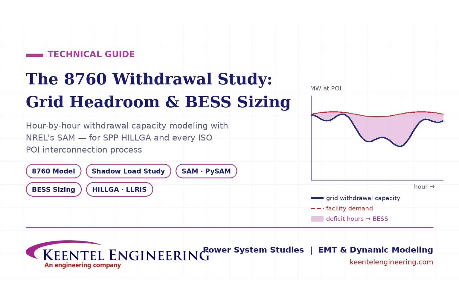
Learn how an 8760 withdrawal study models hourly grid headroom and uses SAM-based BESS sizing for large-load interconnection projects.
By SANDIP R PATEL
•
July 21, 2026
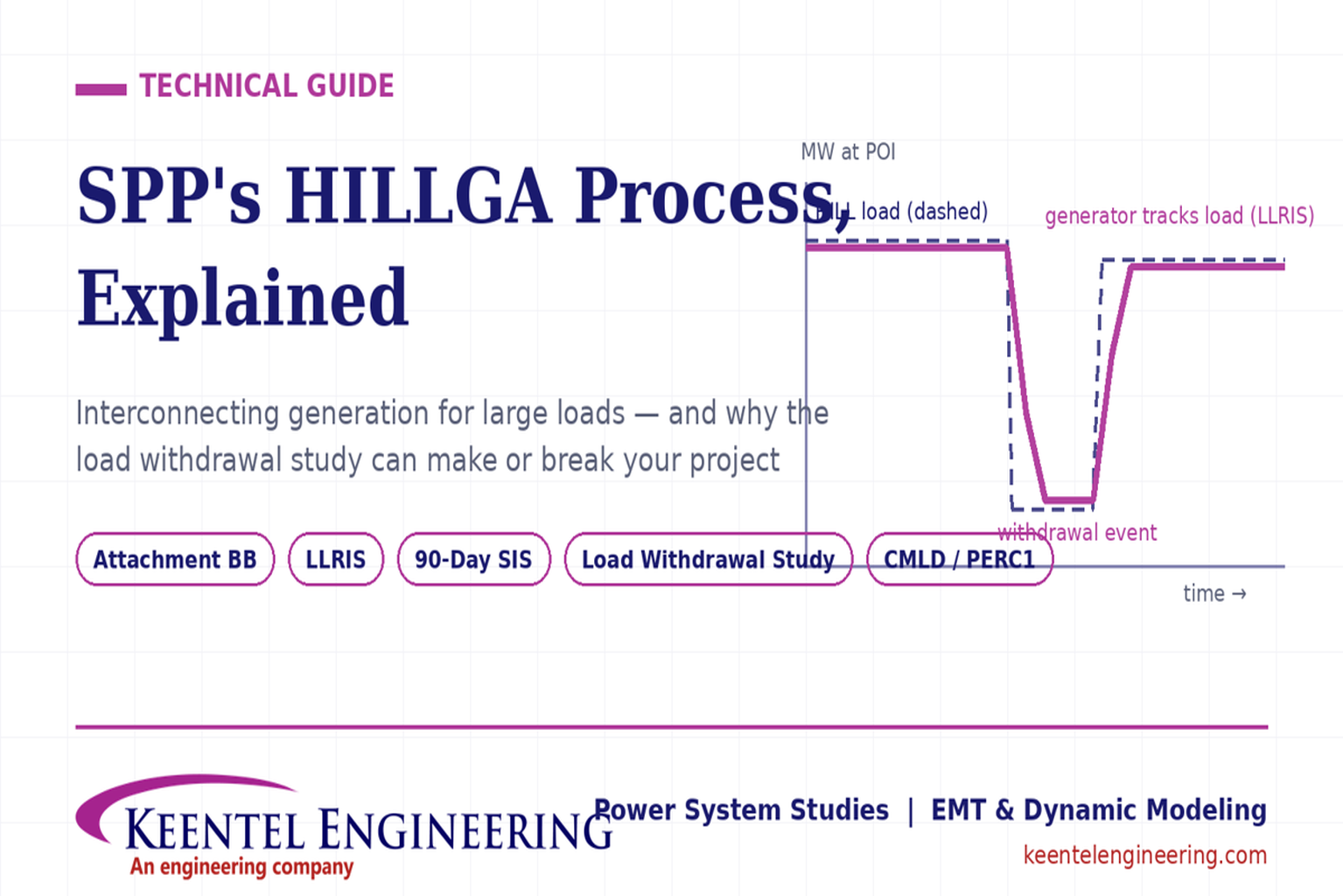
Learn how the SPP HILLGA process supports data center generation interconnection and why an 8760 withdrawal study can determine project success.
By SANDIP R PATEL
•
July 19, 2026
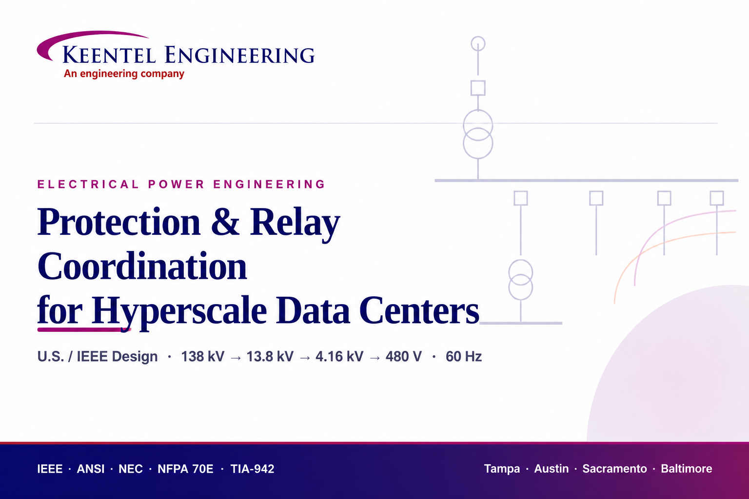
Learn electrical protection and relay coordination for hyperscale data centers with IEEE standards, short-circuit studies, arc-flash analysis, and MV protection.
By SANDIP R PATEL
•
July 18, 2026
Explore Battery Energy Storage System components, including cells, PCS, BMS, EMS, cooling, fire protection, sizing, safety, and grid codes.
By SANDIP R PATEL
•
July 18, 2026
Explore how grid-forming inverters support BESS, synthetic inertia, grid-code compliance, plant sizing, testing, and project revenue.
By SANDIP R PATEL
•
July 18, 2026
Learn how SEL RTAC protection monitoring supports NERC PRC-005 compliance, predictive maintenance alarms, automated reporting, and relay verification.
By SANDIP R PATEL
•
July 17, 2026
Explore utility-scale BESS design from the 10% package to IFC, NFPA 855 compliance, PSS®E/PSCAD models, and ERCOT interconnection.
By SANDIP R PATEL
•
July 17, 2026
Substation design guide, electrical substation design, substation equipment sizing, IEEE 80 grounding design, IEEE 998 lightning shielding, bus configuration design
By SANDIP R PATEL
•
July 15, 2026
Learn how medium-voltage switchgear improves data center reliability with expert guidance on MV architecture, protection, redundancy, commissioning, and maintenance.


