
A Coordinated Electric System Interconnection Review—the utility’s deep-dive on technical and cost impacts of your project.
Challenge: Frequent false tripping using conventional electromechanical relays
Solution: SEL-487E integration with multi-terminal differential protection and dynamic inrush restraint
Result: 90% reduction in false trips, saving over $250,000 in downtime
The three operating regions you have to design to
Transmission Structures: Function First, Form Second
September 3, 2026 | Blog
What Each Structure Class Actually Resists, Why the Angle Categories Between Tangent and Dead-End Are Where Most Lines Live, and What Really Drives the Selection
1. Executive Summary
Transmission structures are usually introduced through a picture chart: suspension, dead-end, transposition, terminal, branch, river crossing, portal; lattice, pole, monopole, H-frame; low voltage through ultra-high voltage. The chart is a reasonable orientation and a poor basis for design, because it names shapes rather than the thing that determines them.
A structure exists to resist a specific set of forces at a specific point on a specific line. Three load directions matter — vertical from conductor weight and ice, transverse from wind and from the line angle, and longitudinal from unequal tension between adjacent spans. What a structure is called follows from which of those it has to resist and how much. Everything else — lattice or pole, steel or concrete, guyed or self-supporting — is a means of resisting them economically, and it is decided second.
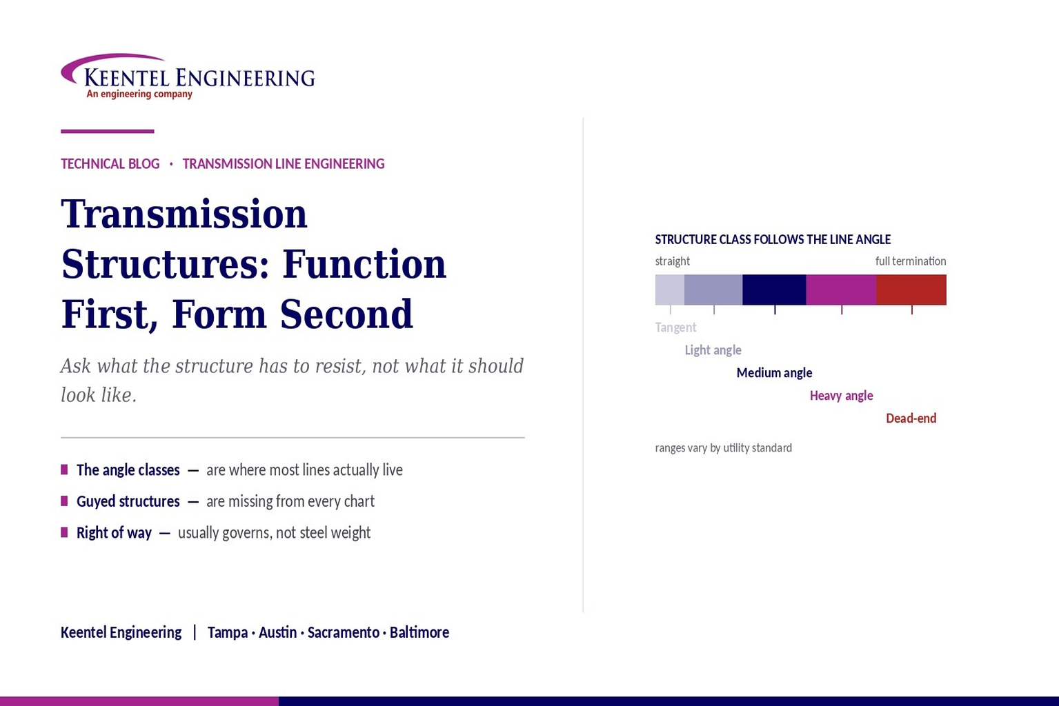
Two gaps in the common charts matter more than any of the entries in them. The first is that the classification jumps from tangent suspension to dead-end, omitting the angle classes in between — light, medium and heavy angle structures — which are where the majority of structures on any real alignment actually fall. The second is that guyed structures are missing entirely, despite being a workhorse of extra-high voltage transmission across large parts of North America and frequently the lowest-cost solution where land and terrain permit.
A third correction matters for anyone working in the United States: the voltage bands in the circulating charts follow an international convention and leave holes exactly where the most common North American transmission voltages sit. One hundred thirty-eight kilovolts and two hundred thirty kilovolts — two of the most heavily used classes on the continent — are not covered cleanly by them.
This paper works through the function classes and the loading each resists, form and material selection including guyed structures, insulator assemblies, the structure family concept, foundations, right of way and geometry, special long-span structures, what transposition actually does and why full transposition is now rare, the North American voltage picture, and what genuinely drives structure selection on a project. It closes with a twenty-five question FAQ.
The framing to carry into a structure selection
Ask what the structure has to resist, not what it should look like. Vertical, transverse and longitudinal load, in what combination, under which governing case, at what line angle and span.
The answer to that determines the class. The form, material and foundation are then a cost optimisation within it.
2. Three Classifications, One Design Decision
The charts present three classifications as though they were parallel. They are not, and understanding their relationship removes most of the confusion.
- Function is the engineering classification. It states what the structure resists and it is the classification a design is actually built on. It follows from the alignment: where the line turns, where it terminates, where a section must be anchored.
- Form and material describe how the resistance is achieved — lattice, pole, frame, guyed; steel, wood, concrete, composite. This is an economic and constructability optimisation performed within the function requirement, not a separate categorisation.
- Voltage class is context rather than classification. It influences the geometry through clearance and insulation requirements, and it correlates with size, but it does not determine the structure type. A dead-end at sixty-nine kilovolts and a dead-end at five hundred kilovolts are the same functional class in very different sizes.
The practical consequence is that a structure is specified by its function class and its capability envelope — the combination of wind span, weight span and line angle it can carry under the governing load cases — and then realised in whichever form is cheapest for that site.
3. Function: What the Structure Has to Resist
The functional classification a line designer actually uses has more categories than the charts show, and the additional ones are the common ones.
| Class | Line angle it handles | What it primarily resists | Design notes |
|---|---|---|---|
| Tangent or suspension | Essentially straight — a small angle only | Vertical load from the weight span, and transverse load from wind on conductor and structure | The most numerous class on any line. Conductor is carried on suspension insulators that swing freely, which is what makes the tension equalise across the section |
| Light angle suspension | A small deviation | The above plus a transverse component from the line angle | Still a suspension structure, with the insulator swing checked under the combined wind and angle load. The angle contribution grows with tension and with the sine of half the angle |
| Medium angle | A moderate deviation | Substantial transverse load, with the angle component becoming comparable to or exceeding wind | Often uses strain or tension insulator assemblies rather than suspension, which changes the tension behaviour of the adjacent spans |
| Heavy angle | A large deviation | Large transverse load with significant longitudinal component | Typically a tension structure with the conductor dead-ended on each side and jumpered across |
| Dead-end, anchor or strain | Any angle including a full termination | Full longitudinal load from the conductor tension on one side, plus transverse and vertical | The strongest and most expensive class. Also used at intervals along straight sections for anti-cascade sectioning — see Section 15 |
| Terminal | Line termination at a substation | Full longitudinal load, plus the geometry to transition into substation take-off structures | A dead-end with additional geometric constraints imposed by the substation arrangement and the required phase spacing at the take-off |
| Branch or tap | A junction where a line divides | Loads from multiple directions with unequal tensions | Requires explicit longitudinal case analysis; the loading is not symmetric and cannot be represented by a ruling-span assumption |
| Transposition | Usually a straight location | Suspension or tension loading plus the geometry to rotate phase positions | A functional requirement layered onto another class rather than a class of its own — see Section 12 |
The specific angle ranges assigned to light, medium and heavy vary between utility standards and between structure families. What does not vary is the principle: the transverse load from the line angle is proportional to the conductor tension and to the sine of half the deviation angle, so it grows rapidly and it is the quantity that pushes a structure from one class into the next.
4. The Loading Cases Behind Each Function
Structure classes exist because the three load directions arrive in different combinations at different points on a line.
- Vertical load comes from the weight of conductor, ice and hardware over the weight span — the distance between the low points of the catenaries either side of the structure. The weight span is not the same as the horizontal span and can be substantially larger or smaller in rolling terrain. It can also become negative, producing uplift.
- Transverse load comes from wind pressure on the conductor over the wind span — half the sum of the adjacent spans — plus wind on the structure itself, plus the resultant of the conductor tensions at an angle structure. On a heavy angle, the angle component dominates.
- Longitudinal load comes from a difference in tension between the two sides. Under normal conditions on a suspension structure it is essentially zero, because the insulators swing and tension equalises. It becomes large under broken conductor, unbalanced ice, stringing operations, and at any structure where the conductor is dead-ended on one side.
That last point explains the entire distinction between suspension and tension construction. A suspension structure is comparatively light because it is not designed to hold unbalanced tension; a dead-end is heavy because it is. Selecting a suspension structure at a location that will see unbalanced longitudinal load, or omitting dead-ends where the security case requires them, is not a sizing error — it is a class error.
Where the ruling span method stops working
Every longitudinal case — broken conductor, unbalanced ice, stringing — involves unequal tension either side of the structure. The ruling span method assumes tension is equal.
Those cases therefore require a finite element sag-tension analysis with the structures and insulators represented as flexible elements. Treating that as an optional refinement is a common way to under-design dead-end and angle structures.
5. Form and Material
| Form | Description | Suits | Trade-offs |
|---|---|---|---|
| Self-supporting steel lattice | Bolted assembly of angle or tubular members, square or rectangular base | High voltage and extra high voltage, long spans, heavy angle and dead-end duty, difficult access where components can be flown or hand-carried | Largest base footprint and four foundations; more members to inspect and maintain; climbing access is straightforward |
| Tubular steel pole | Tapered polygonal or round steel shaft, direct embedded or on an anchor bolt foundation | Constrained corridors, urban and suburban settings, distribution and sub-transmission through to high voltage | Smaller footprint and single foundation; heavier individual piece requiring crane access; deflection and vibration behaviour must be checked |
| H-frame | Two poles connected by a cross-arm, sometimes with X-bracing, in wood, steel or concrete | Long-span tangent and light-angle construction across open terrain at high voltage | Wide but low; efficient use of material for tangent duty; wider right of way than a single pole and less suited to large angles |
| Guyed structures | A mast or frame stabilised by guys anchored outside the structure footprint — see Section 6 | Extra high voltage tangent construction where land permits guy anchors | Lowest steel weight and lowest cost per structure; requires guy easements and clear ground; unsuitable in cultivated or constrained land |
| Wood | Single poles or frames in treated timber | Distribution and sub-transmission, and rural high voltage where economics favour it | Low cost and easy construction; limited height and strength; inspection and replacement programmes for decay; availability of large classes is declining |
| Concrete | Spun or static-cast prestressed concrete poles | Corrosive environments, coastal locations, and markets where the supply chain favours it | Excellent durability and low maintenance; heavy, requiring transport and crane access; difficult to modify in the field |
| Composite | Fibre-reinforced polymer poles and arms | Corrosive and remote locations, fire-exposed corridors, and applications where light weight aids construction | Light, corrosion-immune and non-conductive; higher unit cost; a shorter service history than the alternatives |
6. Guyed Structures: The Missing Category
Guyed structures are absent from the circulating charts and they are a major part of extra-high-voltage transmission across North America and elsewhere. Omitting them from a structure taxonomy is like omitting a whole class of foundation.
The principle is that a slender mast or frame carries the vertical load, while the transverse and longitudinal loads are taken into guys anchored in the ground some distance from the structure. Because the guys provide a long lever arm, the structure itself can be far lighter than a self-supporting structure of the same capability. The common arrangements are a guyed mast, a guyed V — two legs meeting at a point with the arms above — and a guyed portal. Steel weight is typically a fraction of the self-supporting equivalent, and on a long line that difference is the project economics.
The cost is land and access. Guy anchors sit outside the structure footprint, so the easement must cover them, and they obstruct farming, machinery movement and future development. On cultivated land, in constrained corridors, and in urban or suburban settings, guyed structures are frequently unacceptable regardless of their economics.
The engineering considerations are their own discipline. Guy tension interacts with the conductor tension and with structure deflection, so guyed structures should be analysed with the guys represented as flexible elements rather than as fixed supports. Anchor design depends on soil conditions at the anchor location, which may differ from those at the structure. Guy slack under some load combinations, guy vibration, and the consequences of a guy being damaged or removed all belong in the design. And a guyed structure that loses a guy has lost most of its capability, which makes guy protection from vehicle strike a real design item in accessible locations.
7. Insulator Assemblies Follow the Function
The insulator assembly is part of the structure decision, not a separate selection, because it determines how load transfers and how much the conductor can move.
- Suspension assemblies hang vertically and swing freely under wind and angle load. That swing is what equalises tension across a section, and it is also what governs the clearance from the conductor to the structure — the swing case, not the still-air case, sets the arm length.
- V-string assemblies restrain swing by taking the insulator string to two attachment points in a V. They allow narrower arms and a narrower right of way for the same clearance, at the cost of a more complex assembly and different load paths. Where the corridor is constrained, this is a common answer.
- Strain or tension assemblies take the conductor tension directly into the structure, which is what makes an angle or dead-end structure work. They do not swing, so the clearance case is different, and the tension is not equalised through them — which is why they define the boundaries of a tension section.
- Post insulators and braced post assemblies support the conductor rigidly from the structure, common on tubular pole construction. They eliminate swing entirely, which reduces right-of-way width, and they transfer bending into the structure and arm.
Selection interacts with contamination severity, switching and lightning withstand requirements, live-line maintenance practice, and the geometry of the structure family. It should be settled with the structure, not after it.
8. The Structure Family
Production line design does not select an individual structure at each location. It develops a family and spots from it.
A family is a set of related designs sharing a common geometry and detailing: several functional classes — tangent, light angle, medium angle, heavy angle, dead-end — each available in a range of body and leg extensions so that height can be adjusted to terrain without redesign. The result is that a line can be built from a small number of designs and a large number of variants, with corresponding savings in engineering, fabrication tooling, spare parts and construction familiarity.
Each member of the family carries a capability envelope: the maximum wind span, maximum weight span and maximum line angle it can carry, under the load cases the family was developed for. That envelope is what the line designer spots against.
The discipline that keeps this honest is knowing the basis of the envelope. Envelopes are derived from specific load cases — a specific wind, a specific ice thickness, a specific construction grade, a specific conductor. Applying a family developed for one set of conditions to a line designed for another is a common and consequential error, because the numbers look applicable and are not. Where a structure falls outside its envelope, or where the envelope basis does not match the project, the structure requires analytical modelling under its actual loads rather than acceptance against the envelope.
9. Foundations Are Part of the Structure Decision
Structure selection and foundation selection are usually made by different people at different times, and they are one decision.
- A self-supporting lattice tower requires four foundations, each resisting compression on one leg and uplift on the diagonal opposite. Uplift capacity in the site soils is frequently the governing constraint, and it is a geotechnical question rather than a structural one.
- A tubular pole concentrates the entire overturning moment into one foundation, which is either a direct embedment or a drilled shaft with anchor bolts. Moment capacity in weak or saturated soils drives shaft diameter and depth, and can make a pole more expensive than the lattice alternative despite the smaller footprint.
- A guyed structure transfers most load into anchors that may sit in different soil from the structure itself, and anchor uplift capacity governs.
- Grillage, drilled pier, driven pile, micropile and rock anchor solutions each suit different conditions, and the choice interacts with access, water table, rock depth and construction season.
The sequencing failure worth naming is scoping the geotechnical investigation after the structures are spotted. Foundation cost is a substantial fraction of structure cost and it varies enormously along a route; knowing where the difficult ground is before spotting allows structures to be positioned to avoid it. Investigating afterwards produces foundations designed to accommodate locations that were chosen for other reasons.
10. Right of Way, Blowout, and Geometry
Structure geometry and right-of-way width are the same problem viewed from two directions, and right of way is frequently the most expensive and most schedule-critical element of a transmission project.
The required width is driven by the horizontal excursion of the conductor under wind — blowout — plus the clearance required at the edge of that excursion, plus allowances for structure width, access and maintenance. Blowout increases with span length, with wind pressure and with reduced conductor tension, and it is checked at the wind case rather than at rest.
Three geometry choices trade directly against corridor width. Shorter spans reduce blowout but require more structures. Restraining insulator swing — through V-strings or post assemblies — removes the insulator contribution to horizontal movement. And vertical phase configuration on a single pole occupies far less width than a horizontal configuration on an H-frame or lattice tower carrying the same circuit, which is why urban and suburban lines are predominantly pole construction.
Those choices are not free. Vertical configuration increases structure height, which affects visual impact, aviation obstruction assessment and lightning performance. More structures means more foundations and more construction. Restrained assemblies transfer bending into arms. The right answer is site-specific and it is an optimisation, not a preference.
11. Special Structures and Long Spans
Long-span crossings — rivers, estuaries, valleys, shipping channels — are usually presented as a structure type. They are better understood as a design problem that produces a bespoke structure.
The distinguishing feature is that ordinary rules stop applying. The span is far longer than the line standard, so the tension, the sag and the clearance requirement over the crossing all change.
Navigation clearance may be set by a regulatory authority rather than by the electrical code. The structures are tall enough to require aviation obstruction evaluation, marking and lighting. Wind loading on a very tall structure has a different profile from the line standard. Dynamic behaviour — both of the conductor over a very long span and of the structure itself — requires specific attention, and conductor selection may differ from the rest of the line to manage sag and tension.
These structures are almost always dead-ended at both ends of the crossing, isolating the special span from the rest of the line so that its tension and its failure behaviour do not propagate. That is a security decision as much as a mechanical one, and it connects to Section 15.
The other class of special structure worth naming is the one nobody plans for: the location where terrain, land ownership, an existing crossing or a permit condition forces something outside the family. Every long line has a handful. They are disproportionately expensive in engineering hours and they should be identified early, because discovering them during detailed design compresses the schedule at the worst point.
12. Transposition: What It Actually Does
Transposition rotates the phase conductors through the available positions along a line, and the charts describe its purpose as balancing impedance and reducing interference. The first is the substantive reason and it deserves explaining; the second is secondary in modern practice.
Because the three phases occupy different geometric positions, they have different inductances and different mutual couplings to each other and to ground. On an untransposed line those differences produce unequal phase impedances, which in turn produce negative-sequence voltage and current even under perfectly balanced load. That unbalance heats generator rotors, affects protective relay quantities that assume balance, and appears in system studies as an asymmetry that the model must represent.
Transposition equalises the average position of each phase over the section, so the sequence impedances approach the balanced ideal. Its secondary benefit is reducing induced voltage in parallel communication and pipeline facilities, which was a substantial concern historically.
What the charts do not say is that full transposition is now uncommon on new lines. It requires special structures, it complicates construction and maintenance, and on the line lengths typical of modern transmission the resulting unbalance is often within acceptable limits without it. Where unbalance matters — very long lines, lines feeding sensitive load, or lines where a study shows the negative-sequence quantity exceeding a limit — transposition is engineered deliberately. Otherwise the design accepts the unbalance and represents it correctly in the models.
The consequence for studies and protection
An untransposed line has unequal phase impedances, and its sequence parameters differ from the transposed idealisation. Distance relay settings, fault studies and load flow all use those parameters.
Whether a line is transposed is therefore a study input, and modelling an untransposed line as transposed produces relay reach settings and fault currents that are systematically slightly wrong — and for parallel circuits sharing a corridor, the zero-sequence mutual coupling error is not slight.
13. Voltage Classes: The North American Picture
The voltage bands in the circulating charts follow an international convention, and applied to a project in the United States they leave holes exactly where the most heavily used classes sit.
| Class in North American usage | Typical voltages | What it means for structures |
|---|---|---|
| Distribution | Roughly 4 kV to 35 kV | Wood or tubular poles, often with underbuild on transmission structures; clearance and pole class rather than tower design |
| Sub-transmission | Roughly 46 kV to 115 kV | The band the circulating charts skip. Poles, H-frames and light lattice; very common on legacy systems and frequently the subject of rebuild and uprating work |
| High voltage transmission | Roughly 115 kV to 230 kV | The workhorse classes — 138 kV and 230 kV in particular. Poles, H-frames and lattice, with structure type driven by corridor and terrain rather than by voltage |
| Extra high voltage | 345 kV, 500 kV, 765 kV | Bundled conductors, larger insulator assemblies, guyed and self-supporting lattice, wide corridors, and audible noise and field effects entering the design |
| Ultra high voltage | Above the extra-high-voltage classes | Very limited North American application; the international literature is the primary reference |
Two specific holes are worth naming. The band from thirty-five to forty-five kilovolts and the whole sub-transmission range around forty-six and sixty-nine kilovolts falls between the medium-voltage and high-voltage definitions in the circulating charts. And two hundred thirty kilovolts — among the most common transmission voltages on the continent — falls between the top of their high-voltage band and the bottom of their extra-high-voltage band.
The practical point is not that one convention is superior. It is that a specification, a design basis or a scope of work should state the nominal voltage numerically rather than relying on a band label, because the labels do not mean the same thing across markets.
14. What Actually Drives Structure Selection
On a real project the structure decision is rarely made on structural efficiency alone. The following are the drivers, roughly in the order they tend to govern.
| Driver | How it acts | Typical consequence |
|---|---|---|
| Right of way width and cost | Corridor width is set by conductor blowout and clearance; land cost and acquisition risk often dominate project cost and schedule | Pushes toward narrow-profile structures — vertical configuration on poles, restrained insulator assemblies — even where they cost more per structure |
| Land use and guy acceptability | Guy anchors obstruct cultivation, machinery and development | Rules guyed structures in or out before any structural comparison is made |
| Terrain and access | Component weight and crane access determine what can physically be built where | Favours lattice in remote or steep terrain where components can be flown or hand-carried; favours poles where road access exists |
| Geotechnical conditions | Uplift capacity for lattice, moment capacity for poles, anchor capacity for guyed | Can reverse an economic comparison entirely, and is frequently investigated too late to influence it |
| Visual impact and permitting | Public acceptance, scenic designations, and permit conditions | Drives monopole and lower-profile selection in populated and sensitive areas regardless of cost |
| Outage constraints | Rebuilds on live corridors constrain what can be built and when | Favours structures that can be installed quickly or alongside the existing line |
| Standardisation | Utility standard families, existing spares, crew familiarity, established details | Often decisive on utility projects, and worth confirming early rather than proposing an alternative that will not be accepted |
| Structural economy | Steel weight, foundation volume, fabrication cost | The driver everyone starts with, and frequently the one that governs least |
15. Anti-Cascade and Security Loading
One function of dead-end structures is absent from every version of the chart and it is arguably the most important one.
If a conductor breaks or a structure fails, the resulting longitudinal imbalance pulls on the adjacent structures. Suspension structures are not designed to resist substantial longitudinal load, so a failure can propagate structure by structure along the line — a cascade. Historic cascade failures have taken out many kilometres of line from a single initiating event.
The defence is to interrupt the mechanism at intervals. Dead-end or anchor structures placed periodically along straight sections, and at each end of special spans and major crossings, are designed to resist the full longitudinal load and therefore stop propagation at that point. The spacing between them is a reliability and economics decision that belongs in the design basis, and it is one of the reasons dead-ends appear on straight sections where the chart’s logic would not predict them.
The associated analysis is the security load case set — broken conductor, broken shield wire, unbalanced ice — and it cannot be performed with a ruling-span sag-tension method, because every one of those cases involves unequal tension either side of the structure.
16. Reading the Chart Correctly
The angle classes are missing, and they are the common case
The classification jumps from tangent suspension to dead-end. Real alignments are full of light, medium and heavy angle structures, and the transverse load from the line angle — proportional to tension and to the sine of half the deviation — is what moves a structure between classes.
Guyed structures are missing entirely
They are a workhorse of extra-high-voltage transmission and frequently the lowest-cost solution where land permits guy anchors. Omitting them from a structure taxonomy leaves out one of the two fundamental structural strategies.
Tubular steel pole and monopole are the same thing
Listing them as separate structural types confuses a material and form description with a configuration. The meaningful distinctions in the pole category are single pole versus H-frame versus multi-pole, and the material — steel, concrete, wood or composite.
The voltage bands do not fit North America
They follow an international convention and leave gaps at the sub-transmission range and at two hundred thirty kilovolts. State nominal voltages numerically in any specification rather than relying on band labels.
Function is not the same kind of category as form
Function is determined by the alignment and the loading. Form is an economic optimisation within it. A chart that presents them as parallel classifications invites the reader to select a shape and then work out what it can do, which is backwards.
The security role of dead-ends is absent
Dead-ends on straight sections exist to stop cascade propagation. That is a reliability decision with its own load cases, and it explains structure placements the chart’s logic cannot.
17. Keentel Transmission Line Design Services
Transmission line design is core practice at Keentel Engineering. We take lines from route and survey through structure design and construction support, and — less commonly offered — carry the resulting line model into the power system studies that depend on it.
17.1 Route, Survey, and Line Design
- Route selection and optimisation against constructability, land, environmental and permitting constraints, with alternatives evaluated on comparable terms.
- Survey scoping and management across airborne, unmanned aerial and conventional methods, with independent verification of datum, geoid, projection and classification before the surface is used.
- Three-dimensional line model development, structure spotting and optimisation, and as-built model development for existing lines from lidar capture.
- Sag-tension analysis by ruling span and by finite element methods, including longitudinal, broken-conductor, unbalanced ice and uplift cases.
17.2 Structures and Foundations
- Structure family development across tangent, angle and dead-end classes with body and leg extensions, and capability envelope derivation with the load case basis documented.
- Analytical modelling and design of lattice, tubular pole, H-frame and guyed structures under actual loads, with usage verification rather than envelope acceptance.
- Insulator assembly selection and swing analysis, arm geometry, and right-of-way width determination from blowout and clearance.
- Special structure design for long-span crossings, including navigation and aviation requirements, dynamic behaviour and the dead-end isolation strategy.
- Foundation reactions issued by load case with definitions attached, foundation type evaluation, and coordination with the geotechnical programme — scoped early enough to influence spotting.
- Loading case development to the applicable safety code and structural loading guidance, including construction, maintenance and security cases and the anti-cascade dead-end strategy.
17.3 Electrical Design and Studies
- Conductor selection and thermal rating analysis, insulation coordination, shielding and lightning performance, corona and field effects, and grounding and footing resistance design.
- Line constants calculation — sequence impedances, susceptances and zero-sequence mutual coupling for parallel circuits — taken directly from the designed geometry, with transposition represented as built.
- Short-circuit, protective coordination, relay setting, stability and electromagnetic transient studies using those constants.
- Facility rating determination traced to the clearance-limiting analysis, and vegetation clearance basis derived from the model.
17.4 Deliverables, Uprating, and Owner’s Engineer Support
- Plan and profile sets, staking reports, bills of material and cost estimates generated from the model of record; stringing charts, sag tables and construction support; as-built model updating.
- Uprating and reconductoring studies including as-built assessment from lidar, option comparison, structural capacity verification under revised loading, and the downstream rating, protection and model updates that complete the work.
- Owner’s engineer services, design review of third-party line design packages, and independent verification of models and deliverables.
Keentel Engineering holds a Florida Certificate of Authorization and maintains offices in Tampa, Austin, Sacramento, and Baltimore, supporting projects across the interconnections.
18. Frequently Asked Questions
Q1. What actually determines a structure’s type?
What it has to resist. Vertical load from the weight span, transverse load from wind and from the line angle, and longitudinal load from unequal tension between adjacent spans. Which of those arrive and in what magnitude determines the functional class; the form and material are an economic optimisation within that class.
Q2. Why do the charts jump from tangent to dead-end?
Because they are simplifying. Real alignments are full of angle structures — light, medium and heavy — and those are the majority on most lines. The transverse load from a line angle is proportional to conductor tension and to the sine of half the deviation, so it grows quickly and pushes a structure from one class to the next.
Q3. What is the difference between a suspension and a tension structure?
A suspension structure carries the conductor on insulators that swing freely, so tension equalises across the section and the structure sees essentially no longitudinal load in normal operation. A tension structure has the conductor dead-ended into it and resists the full longitudinal pull. That difference is why one is light and the other is heavy.
Q4. What are wind span and weight span?
Wind span is half the sum of the adjacent spans and determines the transverse wind load. Weight span is the distance between the low points of the catenaries either side and determines the vertical load. They are not the same and in rolling terrain they can differ substantially — weight span can even go negative, producing uplift.
Q5. Why are guyed structures missing from most charts?
Only the chart authors know, but the omission is significant. Guyed masts, guyed V and guyed portal structures are a workhorse of extra-high-voltage transmission and frequently the lowest-cost solution where land permits anchors. Their steel weight is a fraction of the self-supporting equivalent.
Q6. When are guyed structures not an option?
Wherever the guy anchors are unacceptable. They sit outside the structure footprint, obstruct cultivation and machinery, complicate future development, and require easement. On farmland, in constrained corridors and in populated areas they are frequently ruled out before any structural comparison happens.
Q7. Are tubular steel pole and monopole different things?
Not really. A monopole is a tubular steel pole. The meaningful distinctions in that category are configuration — single pole, H-frame, multi-pole — and material — steel, concrete, wood or composite. Listing them as separate structural types confuses form with configuration.
Q8. When is lattice preferred over pole?
Where spans are long, loads are heavy, or access is difficult. Lattice components can be flown in or hand-carried into terrain a crane cannot reach, and lattice is efficient for heavy angle and dead-end duty. The trade-off is a larger footprint, four foundations, and more members to inspect.
Q9. Why are poles favoured in urban areas?
Right of way. A vertical phase configuration on a single pole occupies far less corridor width than a horizontal configuration carrying the same circuit, and land cost and acquisition risk usually dominate urban project economics. Visual impact and permitting reinforce the same choice.
Q10. What sets right-of-way width?
Conductor blowout under wind, plus the clearance required at the edge of that excursion, plus structure width and access allowances. Blowout grows with span length and wind pressure and shrinks with tension, and it is evaluated at the wind case rather than at rest.
Q11. How can right-of-way width be reduced?
Shorter spans, restrained insulator assemblies such as V-strings or post assemblies that remove insulator swing, and vertical rather than horizontal phase configuration. Each has a cost — more structures, more complex assemblies, or greater height — so it is an optimisation.
Q12. What is a structure family and why use one?
A set of related designs covering the functional classes, each with body and leg extensions so height adapts to terrain without redesign. It lets a whole line be built from a few designs and many variants, with savings in engineering, tooling, spares and crew familiarity.
Q13. What is the trap with capability envelopes?
They are derived from specific load cases — a specific wind, ice, construction grade and conductor. Applying a family developed for one set of conditions to a line designed for another produces numbers that look applicable and are not. Confirm the basis of the envelope, not just its values.
Q14. When does a structure need analytical modelling rather than envelope acceptance?
Whenever it falls outside its envelope, whenever the envelope basis does not match the project load cases, for any non-standard or reused structure, for guyed structures where guy tension interacts with the line, and for any longitudinal or security load case.
Q15. How do foundations affect structure selection?
Frequently decisively. Lattice needs four foundations with uplift capacity as the usual governing constraint; a pole concentrates the whole overturning moment into one foundation, which weak or saturated soil can make very expensive; guyed structures depend on anchor capacity in soil that may differ from the structure location. Geotechnical conditions can reverse an economic comparison entirely.
Q16. When should the geotechnical investigation happen?
Before spotting, not after. Knowing where the difficult ground is allows structures to be positioned to avoid it. Investigating afterwards produces foundations designed to accommodate locations chosen for unrelated reasons, and foundation cost is a substantial and highly variable fraction of structure cost.
Q17. Why are there dead-ends on straight sections?
Anti-cascade. If a conductor breaks or a structure fails, the longitudinal imbalance pulls on adjacent structures, and suspension structures are not designed to resist it — so a failure can propagate along the line. Dead-ends placed at intervals resist the full longitudinal load and stop propagation at that point.
Q18. What are the security load cases?
Broken conductor, broken shield wire and unbalanced ice — longitudinal cases that establish the line’s resistance to cascading failure. They cannot be evaluated with a ruling-span sag-tension method, because every one of them involves unequal tension either side of the structure.
Q19. What does transposition actually accomplish?
It equalises the average geometric position of each phase, so the phase impedances and the sequence parameters approach the balanced ideal. Without it, unequal geometry produces unequal impedances and therefore negative-sequence unbalance even under balanced load. Reducing induced voltage in parallel communication facilities is a secondary benefit.
Q20. Is transposition still common?
Full transposition is uncommon on new lines. It requires special structures and complicates construction and maintenance, and on typical modern line lengths the resulting unbalance is often acceptable without it. Where a study shows the unbalance exceeding a limit, it is engineered deliberately.
Q21. Does transposition matter for studies and protection?
Yes. An untransposed line has unequal phase impedances and sequence parameters that differ from the transposed idealisation, and those parameters feed distance relay reach settings, fault studies and load flow. For parallel circuits sharing a corridor, the zero-sequence mutual coupling error from assuming transposition is not small.
Q22. Why do the voltage bands in these charts not fit North American work?
They follow an international convention. Applied here they leave gaps at the sub-transmission range around forty-six and sixty-nine kilovolts, and at two hundred thirty kilovolts — one of the most common transmission classes on the continent. State nominal voltages numerically in any specification rather than using band labels.
Q23. What is special about a long-span crossing structure?
That ordinary rules stop applying. The span is far outside the line standard, so tension, sag and clearance all change; navigation clearance may be set by a regulatory authority; height triggers aviation obstruction evaluation and marking; wind profile and dynamic behaviour need specific attention; and conductor selection may differ from the rest of the line.
Q24. Why are crossings dead-ended at both ends?
To isolate the special span from the rest of the line, so its tension and its failure behaviour do not propagate in either direction. It is a security decision as much as a mechanical one, and it is the same logic as anti-cascade sectioning.
Q25. What most often governs structure selection in practice?
Right of way and land, terrain and access, geotechnical conditions, permitting and visual impact, outage constraints, and utility standardisation — roughly in that order. Structural economy, which is where most people start, is frequently the driver that governs least.
References and Further Reading
The following are referenced by subject in the body of this document. The edition adopted by the authority having jurisdiction governs code requirements, and the current published edition of each standard governs its own content.
Loading and Structural Design
- ANSI C2, National Electrical Safety Code — clearance requirements, district and extreme loading cases, overload factors and grades of construction — Institute of Electrical and Electronics Engineers
- ASCE Manual of Practice No. 74, Guidelines for Electrical Transmission Line Structural Loading — American Society of Civil Engineers
- ASCE 10, Design of Latticed Steel Transmission Structures; ASCE 48, Design of Steel Transmission Pole Structures; ASCE Manual of Practice No. 141, Wood Pole Structures; and the ASCE guidance on concrete and fibre-reinforced polymer structures — American Society of Civil Engineers
- ASCE Manual of Practice No. 91, Design of Guyed Electrical Transmission Structures — American Society of Civil Engineers
-
IEC 60826, Design criteria of overhead transmission lines, for projects following the international framework — International Electrotechnical Commission
Foundations, Conductors, and Construction
- IEEE Std 691, Guide for Transmission Structure Foundation Design and Testing — IEEE Standards Association
https://standards.ieee.org/ - IEEE Std 738, Standard for Calculating the Current-Temperature Relationship of Bare Overhead Conductors, and IEEE Std 524, Guide to the Installation of Overhead Transmission Line Conductors — IEEE Standards Association
https://standards.ieee.org/ - CIGRE technical brochures on aeolian vibration, conductor fatigue, galloping, and the application of high-temperature low-sag conductors — CIGRE
https://www.cigre.org/
Electrical Performance and Compliance
- IEEE Std 1243, Guide for Improving the Lightning Performance of Transmission Lines, and IEEE Std 1313.1 and 1313.2 for insulation coordination — IEEE Standards Association
https://standards.ieee.org/ - IEEE Std 80 for substation grounding and IEEE Std 81 for earth resistivity measurement, applicable to structure footing resistance work — IEEE Standards Association
https://standards.ieee.org/ - NERC Reliability Standards — including the facility ratings, vegetation management and relay loadability standards whose inputs originate in the line design model — North American Electric Reliability Corporation
https://www.nerc.com/pa/Stand/Pages/ReliabilityStandards.aspx - FAA obstruction standards and the associated advisory circular on obstruction marking and lighting, where structure heights require evaluation — Federal Aviation Administration
https://www.faa.gov/
Notice and Disclaimer
This document is original technical content prepared by Keentel Engineering LLC for general professional information. It is not project-specific engineering advice and does not constitute a design, a study, or a structure selection for any line. Structure classification, loading, capability and foundation design must be established by project-specific analysis using verified survey, conductor, structural and geotechnical data, and must satisfy the code edition and utility standards applicable to the project.
Classifications, angle ranges and voltage bands described here reflect common North American practice and vary between utilities, standards frameworks and markets. Where a utility standard, specification or code defines a term or a range, that definition governs.
Keentel Engineering LLC is an independent engineering consultancy. Reference to any standard, code, industry organisation, regulator, or equipment category in this document does not imply affiliation with, endorsement by, or sponsorship from any such organisation or manufacturer.

About the Author:
Sandip "Sonny" R. Patel, P.E.
IEEE Senior Member · Founder & CEO, Keentel Engineering
In 1995, Sonny Patel earned his Electrical Engineering degree from the University of Illinois. But degrees don't build legacies — action does.
For three decades, he has worked the power industry from every side of the table: 16 years as a utility engineer at Exelon/Commonwealth Edison; generation leadership across hydroelectric, industrial steam turbine, and a 9 GW renewable fleet; NERC Regional Entity Senior Compliance Engineer and Audit Team Lead, auditing some of the nation's largest utilities; and testing and commissioning lead on equipment up to 765 kV — the very top of the North American grid.Utility. Generator. Regulator. Consultant. Few engineers have seen all four seats. Fewer still have sat in them.
His experience spans nuclear, hydro, conventional generation, renewables, oil and gas, mining — and today's data centers, where he is authoring a three-book series on data center design. He is a Licensed Professional Engineer in six states and a Licensed Electrical Contractor in Florida (Unlimited EC) — he doesn't just design the work; he's qualified to stand behind its execution.Today, as Founder and CEO of Keentel Engineering, Sonny leads a nationwide team of engineers delivering substation design, power system studies, NERC compliance, and commissioning — done right, coast to coast.Three decades. Every side of the table. One standard: accountable engineering.
Services

Let's Discuss Your Project
Let's book a call to discuss your electrical engineering project that we can help you with.
About the Author:
Sandip "Sonny" R. Patel, P.E.
IEEE Senior Member · Founder & CEO, Keentel Engineering
In 1995, Sonny Patel earned his Electrical Engineering degree from the University of Illinois. But degrees don't build legacies — action does.
For three decades, he has worked the power industry from every side of the table: 16 years as a utility engineer at Exelon/Commonwealth Edison; generation leadership across hydroelectric, industrial steam turbine, and a 9 GW renewable fleet; NERC Regional Entity Senior Compliance Engineer and Audit Team Lead, auditing some of the nation's largest utilities; and testing and commissioning lead on equipment up to 765 kV — the very top of the North American grid.
Utility. Generator. Regulator. Consultant. Few engineers have seen all four seats. Fewer still have sat in them.
His experience spans nuclear, hydro, conventional generation, renewables, oil and gas, mining — and today's data centers, where he is authoring a three-book series on data center design. He is a Licensed Professional Engineer in six states and a Licensed Electrical Contractor in Florida (Unlimited EC) — he doesn't just design the work; he's qualified to stand behind its execution.
Today, as Founder and CEO of Keentel Engineering, Sonny leads a nationwide team of engineers delivering substation design, power system studies, NERC compliance, and commissioning — done right, coast to coast.Three decades. Every side of the table. One standard: accountable engineering.
Leave a Comment
Thank you for contacting us.
We will get back to you as soon as possible.
We will get back to you as soon as possible.
Oops, there was an error sending your message.
Please try again later.
Please try again later.
Related Posts

By SANDIP R PATEL
•
October 13, 2026
Plan data center capacity with land screening, MW-per-acre estimates, grid power availability and interconnection feasibility studies from Keentel Engineering.

By SANDIP R PATEL
•
October 11, 2026
Learn which fault produces the highest current at a bus, why SLG faults can exceed three-phase faults, and how symmetrical components determine fault duty.

By SANDIP R PATEL
•
October 11, 2026
Learn why zero-sequence current pulsates in the dq0 frame, how Park's transformation works, and how inverter controls handle unbalance and ground faults.

By SANDIP R PATEL
•
October 11, 2026
Explore grid inertia, RoCoF and frequency response, with swing equation calculations, frequency nadir analysis and US power system simulation examples.

By SANDIP R PATEL
•
October 11, 2026
Learn transient stability analysis, swing equation, equal-area criterion and critical clearing time with a 345 kV worked example and NERC TPL-001 guidance.

By SANDIP R PATEL
•
October 11, 2026
Learn why inverter controls become unstable in weak grids, how PLL bandwidth and SCR affect stability, and how PSCAD EMT studies identify and mitigate oscillations.

By SANDIP R PATEL
•
October 11, 2026
Learn how STATCOMs improve voltage stability and prevent FIDVR. Explore reactive power sizing, delayed fault clearing, NERC criteria and 138 kV simulation results.

By SANDIP R PATEL
•
October 10, 2026
Learn BESS DC sizing with power, energy, current and C-rate calculations, battery losses, degradation and a 100 MW/400 MWh utility-scale example.

By SANDIP R PATEL
•
October 10, 2026
Learn how BESS ROI is calculated using peak shaving, energy arbitrage, power quality and battery storage economics, with a practical 5 MW/10 MWh example.





