
A Coordinated Electric System Interconnection Review—the utility’s deep-dive on technical and cost impacts of your project.
Challenge: Frequent false tripping using conventional electromechanical relays
Solution: SEL-487E integration with multi-terminal differential protection and dynamic inrush restraint
Result: 90% reduction in false trips, saving over $250,000 in downtime
DATA CENTER DESIGN
Power, Cooling, and Reliability from the Grid to the Rack
June 29, 2026 | White Paper
Part I — Foundations
Foundations of Data Center Design
What a data center is, the problems it must solve, and why it behaves unlike any other building.
Chapter 1 — The Data Center as an Energy-Conversion Building
Every email sent, video streamed, transaction cleared, and AI model trained lives somewhere physical — inside a building filled with servers, electrical infrastructure, and cooling equipment that run without pause. From the outside, a data center can look unremarkable: a large, windowless box. Inside, it is something more specific than an information-technology facility. It is an energy-conversion building.
The logic is simple. Electricity enters the building, the servers perform computing work, and essentially all of that electrical energy reappears as heat that must be carried back out. A server does not consume energy the way a motor produces motion; it converts nearly every watt it draws into thermal energy. The entire facility exists to manage that conversion safely and continuously, supplying clean power on one side and removing heat on the other.
This framing matters because it reveals how tightly the two largest engineered systems are coupled. Power and cooling are not separate line items; they are two views of the same number. The cooling plant is sized to remove exactly the heat that the power chain delivers, and the cooling plant is itself one of the largest electrical loads in the building. To understand a data center, one must follow the energy: in as power, through as computation, and out as heat.
Data centers are also extraordinarily energy intensive. Per unit of floor area they can consume on the order of ten to fifty times the energy of a typical commercial office building, and that intensity is rising as computing densities climb. This is why efficiency is not a soft goal but a central engineering and financial concern, and why metrics that capture it — such as PUE (Power Usage Effectiveness) — have become standard language in the industry.
The thread of this book: We will follow energy through the building twice: once as power, from the grid to the rack, and once as heat, from the chip back to the atmosphere. Everything else — redundancy, controls, and interconnection — exists to make that round trip reliable and feasible.
Chapter 2 — The Three Imperatives: Continuous Power, Cooling, and Operation
Regardless of size or purpose, every data center is built to satisfy three imperatives simultaneously. Each one shapes major design decisions, and together they explain most of what distinguishes these facilities from ordinary buildings.
- Continuous power: Servers cannot simply ride out a loss of power. Even a momentary interruption — a fraction of a second — can crash systems, corrupt data in flight, and take services offline for thousands or millions of users. Power must therefore remain available even when utility power is disturbed or fails and even when individual pieces of equipment are out of service. Meeting that standard requires a layered electrical system with power conditioning and multiple independent sources of backup, rather than reliance on the grid alone.
- Continuous cooling: Because servers generate heat every second they operate, cooling must operate every second as well. If it stops, temperatures climb within minutes, forcing equipment to throttle its performance or shut down to protect itself. Cooling in a data center is not a matter of human comfort; it is a matter of equipment survival, and it carries exactly the same intolerance for interruption as the power system.
- Continuous operation: The facility must keep running through maintenance, component failures, and repairs. Equipment will eventually fail, and all equipment must occasionally be serviced. The requirement that none of this interrupt the computing load is what drives the pervasive use of redundancy and multiple independent paths throughout both the electrical and mechanical systems. It is the single most important reason data centers are designed the way they are.
Chapter 3 — Why Data Centers Are Not Like Other Buildings
From the curb, a data center can resemble a warehouse or an office park. Operationally it is a different species of building. In an office, occupancy rises and falls through the day, cooling demand cycles with it, and equipment switches on and off; loads are diverse and intermittent. In a data center, the electrical load is essentially constant, the cooling demand is continuous, and the systems rarely shut down at all.
Failure tolerance differs just as sharply. When cooling fails in an office, people are uncomfortable. When cooling or power fails in a data center, the result is an immediate operational risk: throttling, shutdowns, lost data, and interrupted services. This is why data centers rely on precision cooling systems engineered to hold tight, stable conditions rather than the comfort-cooling equipment used in commercial buildings, and why they are built with redundant equipment, multiple power and cooling paths, and the ability to perform maintenance without shutting down. Those characteristics would be unusual — and unnecessary — in almost any other building type.
Part II — The Electrical System
The Electrical System
Following power from the utility connection through conditioning and backup, all the way to the server rack.
Chapter 4 — From the Grid to the Fence: Utility Supply and Interconnection
Power begins far from the building. It is generated from a mix of sources — natural gas, nuclear, hydroelectric, coal, wind, and solar — and delivered by the local utility. To move energy efficiently over long distances, utilities transmit it at very high voltage and correspondingly low current. The reason is physical: resistive losses in a conductor rise with the square of the current, so raising voltage to reduce current sharply reduces losses. Power travels across the transmission network to substations, where the voltage is stepped down and routed toward the data center campus.
When power reaches the site, it enters through service entrance switchgear — the first major piece of on-site electrical equipment and the point at which the facility takes control of its own power. Service switchgear receives the incoming utility supply, provides overcurrent protection, segments distribution paths, allows circuits to be isolated for maintenance, and houses metering and protective relays.
Interconnection Is the Gate
For most facilities the utility supply arrives at medium voltage, commonly in the range of roughly 12 to 34.5 kilovolts. But as campus loads have grown into the hundreds of megawatts, large facilities increasingly take service at sub-transmission or transmission voltages instead. That shift carries the project into the formal utility interconnection process — a subject Keentel's POI Interconnection Engineering team navigates regularly. The connection to the grid is not a given; it is engineered, studied, and increasingly the gating item for whether a project can proceed at all.
Chapter 5 — The On-Site Power Chain: Switchgear to Rack
Inside the fence, power moves through a sequence of controlled voltage transformations and protected distribution stages, each taking electricity one step closer to the sensitive electronics in the racks. The full chain, from the grid to the server, is summarized below.
| Stage | Function | Typical voltage |
|---|---|---|
| Utility / transmission | Generated and transmitted at high voltage to minimize line losses | Transmission (above 35 kV) |
| Substation | Steps voltage down; routes power to the campus | High to medium voltage |
| Service entrance switchgear | Protection, isolation, metering, protective relays | Medium voltage (~12-34.5 kV) |
| Step-down transformer | Converts medium voltage to building distribution voltage | MV to 480 V |
| Generators + paralleling / transfer gear | Start and assume full load on a utility outage | 480 V |
| UPS (N+1 modules) | Conditions power; instantaneous battery bridge | 480 V |
| Output switchboard / distribution switchgear | Breaker protection, branch segmentation, isolation | 480 V |
| PDU (power distribution unit) | Steps down again; branch protection; monitoring | 480 to 208 / 415 V |
| RPP (remote power panel) | Extends branch circuits into the white space | 208 / 415 V |
| Rack PDU (rPDU) | Feeds individual servers; per-outlet monitoring | 208 / 120 / 240 V |
| Servers | Convert power to computation; nearly all becomes heat | Low-voltage DC internally |
After the medium-voltage supply is stepped down by transformers to a building distribution voltage — commonly 480 volts three-phase — it passes through the backup chain (generators and UPS, covered in the next two chapters) and into output switchboards and distribution switchgear that provide breaker protection, segment branches, and allow isolation for maintenance. From there, power distribution units (PDUs) step the voltage down again and provide branch-circuit protection and load monitoring for groups of racks. Remote power panels (RPPs) extend branch circuits deeper into the white space, improving scalability and allowing layout changes without major rework. Finally, rack power distribution units mounted inside each cabinet feed individual servers, often with per-outlet monitoring and remote switching.
A and B paths and dual-corded loads: In the most resilient designs, this distribution is duplicated end to end into two independent paths — conventionally the A side and the B side — fed from separate sources through separate UPS systems and PDUs. Servers with dual power supplies are corded to both, so the loss of either side, from a fault or from planned maintenance, leaves the equipment running on the other. For equipment with only one power input, a static transfer switch can move the load between A and B sources in milliseconds. This dual-path arrangement is what allows an entire power path to be taken out of service while the IT load continues uninterrupted. For a deeper dive into data center electrical design principles, see Keentel's dedicated engineering guide.
Chapter 6 — Uninterruptible Power Supplies
Distributing power is not enough; it must also be clean and uninterrupted. Utility power carries voltage fluctuations, frequency variations, transients, and occasional outages, and sensitive electronics react badly to even brief disturbances. The uninterruptible power supply (UPS) sits between the incoming power and the critical load, serving two roles at once: it conditions the power, and it provides an instantaneous source of backup energy.
The double-conversion topology: A UPS has three core elements: a rectifier, an energy store (typically batteries), and an inverter. In the dominant data center design — the double-conversion UPS — incoming alternating current is converted to direct current by the rectifier. That DC bus simultaneously charges the batteries and feeds the inverter, which reconverts it into clean, tightly regulated AC for the load.
The decisive feature is that the load is always supplied by the inverter, never directly by the utility. The input is fully decoupled from the output, so disturbances are filtered out before they can reach a server, and the response to an outage is seamless: when utility power fails, the rectifier simply stops receiving input while the already-charged batteries continue feeding the same inverter. There is no switchover, no transfer time, and no flicker — which is precisely what the name promises. Smaller or edge applications sometimes use a line-interactive UPS, which regulates voltage and switches to battery only when needed with a brief transfer; mission-critical facilities favor double conversion for its superior power quality and true zero-transfer behavior. Some units offer an economy mode that bypasses the conversion to save energy at the cost of some isolation, a reliability-versus-efficiency decision.
Battery technologies: UPS batteries are sized to carry the full load for only a short bridge period, typically a few minutes up to around fifteen. That is by design: the batteries exist to span the seconds it takes for generators to start and stabilize, not to ride out a long outage. Two technologies dominate, and the choice balances cost, footprint, and life.
| Attribute | Valve-Regulated Lead-Acid (VRLA) | Lithium-Ion |
|---|---|---|
| Upfront cost | Lower | Higher |
| Footprint & weight | Larger and heavier | Compact and lighter |
| Service life | Shorter (often ~3-5 years) | Longer (often ~10+ years) |
| Temperature tolerance | More sensitive | Tolerates higher temperatures |
| Monitoring | Basic; more manual maintenance | Integrated battery management system |
| Typical fit | Cost-driven or legacy installs | Modern high-density facilities |
UPS plants are typically arranged in N+1 modular configurations, so that if one module fails or is serviced the remaining modules continue carrying the load, and they include static bypass and maintenance bypass provisions so the unit can be worked on without dropping the IT load.
Chapter 7 — Backup Generation and the Power Handoff
Batteries bridge seconds and minutes; generators carry the facility through hours and days. Most large data centers use diesel generators, frequently rated at several megawatts each and operated in parallel to support the full load with redundancy. In smaller facilities, transfer between utility and generator is handled by an automatic transfer switch (ATS); in larger ones, the transfer logic is integrated into generator paralleling switchgear that detects the utility failure, starts the generators, synchronizes their output, and transfers the building load.
Generators are mechanical machines and need time to start and reach stable voltage and frequency — typically on the order of ten seconds to under a minute depending on their emergency-power classification. On-site fuel storage commonly provides hours to a few days of autonomy, and arranged deliveries extend that during prolonged grid events. Because servers cannot tolerate even milliseconds of interruption while the generators spin up, the UPS bridges the gap. The full sequence, which runs automatically with no human intervention, is as follows:
- Utility power is lost.
- The UPS instantly carries the load from its batteries through the same inverter, with no transfer time.
- The transfer scheme detects the outage and signals the generators to start.
- The generators reach stable voltage and frequency and accept load, typically within about ten seconds to under a minute.
- The transfer switch or paralleling gear moves the building load onto generator power.
- The UPS, now fed by the generators, recharges its batteries while continuing to condition power.
- When utility power returns and stabilizes, the system transfers back and the generators shut down after a cooldown.
Redundancy applies here as everywhere: an N+1 generator plant installs one unit beyond the number required to carry the load, so a single generator can fail or be serviced without compromising backup capacity.
Chapter 8 — Power System Studies and Protection
Redundant equipment delivers reliability only if the system connecting it is engineered correctly, and that correctness is established through analysis rather than assumed. A sound data center electrical design rests on several power system studies, each answering a specific question about how the system behaves under normal and fault conditions.
- Load flow analysis confirms that voltages and equipment loadings stay within limits across normal and contingency configurations, including when the facility runs on generator power.
- Short-circuit analysis establishes the fault currents the system must withstand, so that breakers and switchgear are rated to interrupt them safely.
- Protective device coordination tunes relays and breakers so the device nearest a fault clears it first, isolating the smallest possible section and preserving uptime everywhere else.
- Arc-flash analysis quantifies the incident energy at each location, driving the labeling and protective-equipment requirements that keep maintenance work safe.
These studies are what separate a system that is redundant on paper from one that actually rides through faults and maintenance without dropping the load. Arc-flash analysis in particular is a prerequisite for genuine concurrent maintainability: a path can only be safely serviced while energized if the hazard at that location is understood and controlled. Performing and maintaining these studies, and designing the switchgear and protection schemes they inform, is core power-systems engineering work and a central part of how a facility earns the reliability its redundancy promises. Keentel's Power System Studies provide the analytical backbone for these critical evaluations.
Part III — The Mechanical System
The Mechanical System
Following heat from the rack back out to the atmosphere, across the full spectrum of cooling architectures.
Chapter 9 — The Thermal Problem and Air Management
Once power reaches the servers, electrical engineering hands off to mechanical engineering. Every watt delivered becomes heat that must be removed instantly, continuously, and reliably. The scale of that heat is easy to underestimate. A seated person gives off roughly 400 to 450 BTU per hour. A single rack of IT equipment can give off far more, as the table below shows.
| Heat source | Approximate heat output |
|---|---|
| One seated person | 400-450 BTU/hr (~0.12 kW) |
| IT rack at 5 kW | ~17,060 BTU/hr |
| IT rack at 30 kW | ~102,360 BTU/hr |
| AI / GPU rack at 100 kW | ~341,000 BTU/hr |
Air is a relatively poor medium for carrying this heat; liquid can transfer roughly four times as much heat as air of the same mass. As rack densities rise, air-based systems must move ever larger volumes of air, which means bigger fans, higher fan speeds, more fan energy, and more noise, until they reach physical limits. Managing the air that is moved therefore becomes as important as the cooling equipment itself.
Racks, blanking, and the raised floor: IT equipment is mounted in standardized racks, typically about seven feet tall, lined up in rows. Within a rack, blanking panels cover unused openings so that cold supply air is forced through the equipment rather than leaking around it, and gaps between cabinets are sealed for the same reason. In many larger air-cooled facilities, a raised floor (commonly six to thirty inches high) serves as a pressurized supply-air plenum: cold air is delivered beneath the floor and rises into the cold aisles through perforated tiles placed only where cooling is needed.
The mixing problem: The defining inefficiency of air cooling is the mixing of hot exhaust with cold supply air before it reaches the equipment. In an open room with no containment, hot air migrates over the tops of the racks and recirculates into the intakes — a short-circuit that raises inlet temperatures and creates hot spots, while cold air that bypasses the equipment wastes capacity. The governing principle of air management is therefore simple to state and powerful in effect: keep the cold supply air and the hot return air from mixing. Cold air should reach the equipment without contamination, and hot air should return to the cooling units without diluting the supply.
Chapter 10 — Containment: Hot Aisle and Cold Aisle
The first discipline that makes air management possible is arranging racks into alternating hot and cold aisles, with rack fronts facing each other across a cold aisle and rack backs facing each other across a hot aisle. This organizes airflow, but on its own it does not stop the two streams from mixing above and around the rows. Containment closes those gaps by physically enclosing one of the aisles, using ceiling panels or baffles, end-of-row doors, and blanking, so the air has only one path.
- Cold-aisle containment: Here the cold aisle is enclosed. Supply air is trapped in front of the racks so every server receives consistent, low-temperature intake air, while hot exhaust is allowed to fill the rest of the room. It is generally simpler and lower in cost, especially as a retrofit to a raised-floor hall, and it delivers uniform inlet temperatures. Its limitations are that the general room runs warm and that, at very high densities, insufficient cold air can reach the racks.
- Hot-aisle containment: Here the hot aisle is enclosed instead, capturing exhaust immediately and routing it — often through an overhead plenum or ductwork — back to the cooling units, while the rest of the room is flooded with cool supply air. It is typically more efficient and performs better at high density, because the return air is captured hot and undiluted, which lets the cooling coils run at a larger temperature difference. Its costs are greater design complexity and the need to coordinate carefully with fire detection and suppression.
| Attribute | Cold-Aisle Containment | Hot-Aisle Containment |
|---|---|---|
| What is enclosed | Cold supply aisle (rack fronts) | Hot exhaust aisle (rack backs) |
| Room condition | Room runs warm | Room runs cool |
| Primary objective | Consistent inlet temperature | Efficient return-air management |
| High-density performance | Falls off as density rises | Strong; scales well |
| Cost & complexity | Lower; simpler retrofit | Higher; more coordination |
| Best fit | Retrofits, moderate density | High-density and AI builds |
The supply-air temperature must be chosen with care: set it too low and energy is wasted; set it too high and the rack runs too hot. Because control of the return air is what makes the rest of the cooling plant efficient, hot-aisle containment is generally preferred when designing high-density facilities, where cold-aisle containment can struggle to deliver enough cold air to the equipment. For a complete analysis of thermal management strategies, explore Keentel's detailed engineering resource.
Chapter 11 — Precision Cooling Units: Room, Row, and Rack
The equipment that actually conditions the air comes in several forms and can be deployed at three scales, serving a whole room, a row, or an individual rack. Two foundational room-based units have served data centers for decades, and they are frequently confused because they look almost identical from the outside. They are not the same.
CRAC versus CRAH: A CRAC, or computer room air conditioner, contains its own refrigeration circuit — compressor, refrigerant, expansion valve, and evaporator coil — and creates cooling internally, rejecting heat outdoors through a condenser, dry cooler, or water-cooled condenser. It is essentially a large precision air conditioner dedicated to the data center. A CRAH, or computer room air handler, contains no compressor or refrigerant; instead it circulates chilled water from a central plant through a coil, and simply transfers cooling from that chilled water into the room air. The single difference — internal refrigeration versus reliance on a central chilled water plant — changes nearly everything about how the systems scale, how efficient they are, and how they are maintained.
| CRAC (air conditioner) | CRAH (air handler) | |
|---|---|---|
| Cooling source | Internal refrigeration (DX) | Chilled water from a central plant |
| Key components | Compressor, refrigerant, evaporator coil | Chilled water coil, fans, filters |
| Operates independently? | Yes, self-contained | No, depends on chiller plant |
| Efficiency at scale | Lower | Higher |
| Typical fit | Smaller facilities | Large and hyperscale facilities |
In a typical raised-floor arrangement, these units sit on the floor and deliver cold air downward into the underfloor plenum, from which it rises through perforated tiles into the cold aisle; warm return air is drawn back into the top of the unit. Because chilled water can move large amounts of heat efficiently and a central plant can be optimized as a whole, hyperscale facilities commonly favor CRAH-based chilled water systems.
Close-coupled cooling: in-row and in-rack: As densities rise, room-based units reach their limits and create hot spots, so cooling is brought closer to the heat. In-row units sit between the racks, drawing hot air from the hot aisle and discharging cold air into the cold aisle; each typically serves one row, can be fed by chilled water or be self-contained, allows different cooling capacities for rows with different loads, and does not require a raised floor. In-rack solutions go further still, mounting a heat exchanger on or in a single rack, with a rear-door heat exchanger on the back of the cabinet capable of removing on the order of 60 kilowatts per rack. Many facilities mix room, row, and rack approaches to match varying densities across the floor.
The cooling distribution unit (CDU): Where liquid is brought to the rack, a cooling distribution unit provides the critical separation between the fluid circulating in the IT equipment and the water in the outdoor heat-rejection system. A heat exchanger inside the CDU keeps the two loops from ever mixing, so the rack-side fluid is unaffected by the quality of the outdoor water, while redundant pumps circulate the secondary loop to the racks. The CDU deliberately supplies fluid above the dew point to avoid condensation, can reject heat through a dry cooler or cooling tower without chillers or compressors, and holds only a small volume of fluid in its secondary loop, which limits the consequences of a leak. CDUs are central to the liquid-cooling systems described in Chapter 14.
Chapter 12 — Chilled Water Systems
Air moves heat around inside the hall, but it does not remove heat from the building. At scale, that work is done by a chilled water plant, which uses water — a dense and effective heat-transport medium — to carry heat from the data hall to the outdoors. The loop is conceptually straightforward and runs continuously: a chiller produces cold water; pumps send it to coils in the air handlers; room air passes over the coils and is cooled; the warmed water returns to the chiller; and the chiller rejects that heat to the outside environment.
Major components: Chillers are the heart of the plant, using a refrigeration cycle to remove heat from the water; they are either air-cooled, rejecting heat directly to outdoor air, or water-cooled, rejecting heat to a condenser-water loop served by cooling towers (the subject of the next chapter). Pumps keep water moving, commonly separated into primary pumps that circulate a stable flow through the chillers and secondary pumps that deliver variable flow to the building loads. Air handlers (CRAH units) hold the chilled water coils in the data hall, transferring heat from the room air into the water.
A key efficiency metric is the system delta-T — the temperature difference between supply and return water: a larger delta-T means each unit of water carries more heat, so a given load can be served with less pumping energy. Good air management and containment support a healthy delta-T by keeping return air hot and undiluted. Chilled water plants are built with layered redundancy, often N+1 across chillers, cooling towers, condenser-water pumps, and chilled-water pumps, so the failure of any single component does not interrupt heat removal.
Chapter 13 — Heat Rejection: Air-Cooled, Water-Cooled, and Economizers
Every cooling system ultimately faces the same final task: getting the heat out of the building and into the environment. The biggest architectural choice in a data center cooling plant is how that final rejection happens, and it comes down to one distinction.
In an air-cooled system, heat is rejected directly to the outdoor air, using equipment such as air-cooled chillers, condensers, or dry coolers in which fans blow outdoor air across coils. In a water-cooled system, heat is transferred into a water loop and rejected through cooling towers, where evaporating a portion of the water removes heat very effectively. A common point of confusion is worth clearing up: air-cooled does not mean servers are cooled only by air, and water-cooled does not mean water flows to the servers. Many air-cooled facilities still circulate chilled water inside the building; the term refers to how heat is ultimately rejected outdoors.
| Air-Cooled | Water-Cooled | |
|---|---|---|
| Heat rejection | Directly to outdoor air (fans, coils) | Through a water loop and cooling towers (evaporation) |
| Water use | Little or none | Significant (evaporation) |
| Complexity | Simpler; no towers or condenser-water pumps | More complex; towers, pumps, water treatment |
| Efficiency | Lower, especially in hot climates | Higher, especially at large scale |
| Best fit | Smaller, edge, water-constrained, retrofit | Large and hyperscale, high cooling loads |
Neither is automatically better. Air-cooled systems conserve water but tend to use more electricity, while water-cooled systems are more efficient but consume water and demand more maintenance and careful water treatment to prevent scaling, corrosion, and fouling. The choice depends on climate, utility costs, water availability, rack density, sustainability goals, and long-term operating strategy. Two metrics capture the trade-off: power usage effectiveness (PUE), which measures overall energy efficiency, and water usage effectiveness (WUE), which measures water consumption. A drought-prone site may favor air cooling to save water; a large hyperscale facility may favor water cooling for the energy savings.
Economizers and free cooling: A major advantage of many systems is economization, or free cooling, in which favorable outdoor conditions are used to reject heat with little or no mechanical refrigeration. Air-side economizers bring filtered outdoor air into the space; water-side economizers use cooling towers or fluid coolers to make cooling directly when the outdoor wet-bulb temperature is low enough. A less common but elegant third option is the refrigerant economizer.
The refrigerant economizer: A refrigerant economizer achieves free cooling by adding a refrigerant pump, distinct from the compressor, that circulates refrigerant when outdoor conditions allow the compressor to be turned off. The pump uses less than a tenth of the energy of a compressor, which is the source of the savings. It takes sub-cooled liquid leaving the condenser and moves it to the expansion valve while maintaining the differential pressure needed for proper operation. The approach exploits a useful property of refrigerant: it carries roughly twice the heat of water and on the order of forty times that of air, which allows smaller pipes and avoids the large ducts and outdoor-air contamination associated with air-side economizers. These systems operate in three modes.
| Mode | How it operates |
|---|---|
| Full compressor | Compressor runs; the refrigerant pump is bypassed (unfavorable outdoor conditions) |
| Full economizer | Compressor off; the refrigerant pump circulates refrigerant (favorable outdoor conditions) |
| Mixed mode | Two circuits: one pumps refrigerant in economizer mode while the other runs its compressor |
Refrigerant economizers are built as split systems, with the condenser and a separate refrigerant-pump enclosure outdoors and the compressors and evaporator coil indoors, or as packaged units that house the condenser, compressor, evaporator, and pump together and duct supply and return air to the space. In either case the supply and return air paths must be kept separate to prevent short-circuiting before the air reaches the IT equipment.
Chapter 14 — Liquid Cooling for AI: Direct-to-Chip and Immersion
For decades, air cooling was the backbone of the industry, and for traditional servers it worked well. Artificial intelligence has changed the rules. A conventional rack once drew 5 to 15 kilowatts; modern AI servers, packed with GPUs, can each draw tens of kilowatts, and a single rack can now reach 50, 80, over 100, and in the newest deployments approach 200 kilowatts. The challenge is not supplying the power; it is removing the heat, and at these densities air alone cannot do it efficiently. The principle is intuitive: to cool a red-hot piece of metal you could blow air across it, or you could put it in water, and the water removes heat dramatically faster. The same logic now drives data center design toward bringing liquid as close to the processor as possible.
Direct-to-chip cooling: Direct-to-chip cooling, currently the most common liquid approach in AI facilities, mounts a cold plate directly on the hottest components, typically CPUs and GPUs. Cool liquid flows through small channels in the cold plate, absorbs heat as the processor generates it, and carries that heat out of the server, much as the coolant loop in a car engine works. The warmed liquid returns to a cooling distribution unit, which transfers the heat into the facility cooling system and sends the coolant back. The advantage is efficiency: instead of cooling the whole room, the system cools the exact components producing the most heat, enabling far higher densities with much less airflow. Most direct-to-chip systems are hybrids, however, because components not connected to cold plates still need some air cooling.
Immersion cooling: Immersion cooling is the most extreme form. Rather than bringing liquid to the server, it places entire servers into tanks of specially engineered dielectric fluid that does not conduct electricity, so components operate safely while fully submerged and the surrounding fluid absorbs their heat directly. In single-phase immersion, the fluid stays liquid and is circulated to a heat exchanger; in two-phase immersion, the fluid boils on contact with hot components, and the vapor rises, condenses on a cooling surface, and returns as liquid in a continuous cycle. Immersion supports extremely high densities and largely eliminates server fans and airflow management, but it introduces challenges in maintenance, hardware compatibility, operating procedures, and facility design, which is why it remains less common than direct-to-chip cooling even as interest grows.
Heat still has to leave the building: Removing heat from the server is only half the task. Whatever method is used, the heat collected by the liquid must ultimately move into the facility's mechanical infrastructure — chilled water systems, cooling towers, dry coolers, or fluid coolers — and then to the outdoors. The configuration varies, but the principle is fixed by thermodynamics: heat travels from the processor to the liquid, from the liquid to the cooling system, and eventually to the atmosphere. Every watt entering the data center must leave it as heat. As AI workloads continue to grow, the question is no longer whether liquid cooling will be used, but how much of the facility will eventually be liquid cooled.
Part IV — Reliability and Integration
Reliability and Integration
The principles that bind power and cooling into one dependable, buildable facility, and connect it to the grid.
Chapter 15 — Redundancy and Tier Classification
The imperative of continuous operation expresses itself everywhere as redundancy: spare capacity and duplicate paths so that a failure or a maintenance event is absorbed without ever reaching the IT load. The same vocabulary applies to both electrical and mechanical systems, and it is built on a single letter.
N is the amount of equipment required to serve the full load. If a facility needs three chillers, or four UPS modules, that quantity is N. The common redundancy levels build from there.
| Level | Meaning | Tolerates |
|---|---|---|
| N | Exactly the required capacity, no spare | Nothing; any failure reduces capacity |
| N+1 | One spare beyond the requirement | A single failure or one unit in maintenance |
| N+2 | Two spares beyond the requirement | A failure while another unit is offline |
| 2N | Two fully independent systems, each at 100% | Loss of an entire system or path |
| 2N+1 | Duplicated systems plus a spare | A failure within a path while its twin is serviced |
N+1 is the most common level, offering a strong balance of reliability and cost; 2N duplicates the entire infrastructure — two utility feeds, two switchgear lineups, two UPS systems, and two distribution paths, each able to carry the full load. Distributed-redundancy schemes (for example, arranging systems so that any sufficient subset can carry the load) can achieve fault tolerance with less than full duplication. In practice, redundancy is layered across the whole facility — electrical feeds, generators, UPS plant, and distribution paths on one side, and chillers, cooling towers, condenser-water pumps, chilled-water pumps, and in-room units on the other.
Tier classifications: These levels map onto the industry tier classifications used to describe overall reliability.
| Tier | Defining characteristic | Typical redundancy |
|---|---|---|
| Tier I | Basic capacity; single, non-redundant path | N |
| Tier II | Redundant capacity components; single path | N+1 components |
| Tier III | Concurrently maintainable: any component or path can be serviced without downtime | N+1, multiple paths (one active) |
| Tier IV | Fault tolerant: absorbs a single worst-case failure with no impact | 2N or 2N+1, multiple active paths |
Two distinctions matter most. Concurrent maintainability, the threshold for Tier III, means any single component or distribution path can be removed from service without affecting the load, which requires both redundant components and independent distribution paths. Fault tolerance, the hallmark of Tier IV, means the facility can absorb an unplanned single failure with no impact, generally implying a 2N architecture with multiple active, physically separated paths. Layered correctly, this is what lets well-run facilities target availability around 99.999 percent, the so-called five-nines level, equivalent to roughly five minutes of downtime per year. Crucially, the cooling and electrical systems should be designed to the same standard, because the facility is only as resilient as its weakest system.
Chapter 16 — Controls, Monitoring, and Integration
The third major system group is the least visible and easily underestimated, yet it is what turns a collection of equipment into a coordinated, self-protecting facility. Building management and automation systems supervise the mechanical plant; electrical power monitoring systems watch the power chain; and data center infrastructure management software ties the whole picture together. These systems continuously track temperatures, power draw, equipment status, and alarms, and they act on what they observe — staging cooling capacity up and down to match load, initiating failover when a component drops out, and alerting operators before a developing problem becomes an outage.
In a building whose defining requirement is continuous operation, this automated awareness is a core reliability system, not a convenience. The critical handoffs that keep the load alive — UPS to generator, primary cooling to backup — occur on timescales far too short for human reaction, so the controls layer must be engineered with the same rigor as the equipment it governs. It is also the layer where the two halves of the facility meet: controls are what allow power and cooling to be operated as one integrated system rather than two independent ones, which is the foundation of the integrated design philosophy that closes this book.
Chapter 17 — Before the Load Arrives: Interconnection and Site Viability
There is a layer upstream of everything in this book, and it has become the decisive one. All of the internal infrastructure described so far presumes that the facility can secure the grid capacity it needs, and at modern scale that is no longer a safe presumption. Driven in large part by the rising densities reshaping cooling, campus loads now routinely reach into the hundreds of megawatts. That pushes utility service from distribution voltages up toward sub-transmission and transmission, and brings the project squarely into the utility interconnection process.
That process is substantial. It involves securing a position in the interconnection queue, completing system impact and facilities studies, performing point-of-interconnection engineering, and meeting the protection and modeling obligations that come with connecting a large load to the bulk power system — including, where applicable, compliance with NERC operations and planning standards. Increasingly, these realities govern site viability and project schedule more than any decision made inside the building. Keentel's Owner's Engineer services are designed to navigate these complexities from the earliest project phases.
The central lesson: The most elegantly engineered power chain and cooling plant are worth nothing if capacity cannot be delivered to the site on a workable timeline. Interconnection belongs at the front of the design conversation, not the end of it. A site should be evaluated for deliverable power and a credible path to energization before the internal design is committed. This is why data center site viability must be confirmed before major capital commitments. Understanding the large load interconnection requirements is essential for any project exceeding 50 MW.
This is the discipline that Keentel Engineering specializes in, and it is the reason this book treats the grid connection as a first-order design input. Evaluating a site for its interconnection prospects, sizing the load against what the grid can realistically deliver, and engineering the point of interconnection are not downstream formalities; they are the foundation on which the feasibility of the entire facility rests.
Chapter 18 — Integrated Design: Bringing Power and Cooling Together
The recurring theme of this book is that a data center is a single integrated system, not a stack of independent ones. The energy-conversion framing of the first chapter is the key: power in and heat out are two views of the same flow, and they must be designed against each other. The cooling plant is one of the largest electrical loads in the building, so a more efficient thermal design lowers total facility power for the same computing capacity, improves PUE, and reduces the load that must be secured from the grid. A cooling decision is therefore also a power decision, and a power decision constrains what cooling is feasible.
Integration runs through every part of the design. Redundancy must be matched across the electrical and mechanical systems so that neither becomes the weak link. The controls layer must operate power and cooling as one coordinated environment, because the handoffs that protect uptime cross both domains. And the whole internal design must be anchored to the interconnection that determines whether and when the facility can be energized. Treating these as separate workstreams produces facilities that are individually optimized and collectively fragile.
This is the value of an owner's-engineer perspective that spans the full picture: from the point of interconnection and the power system studies that make the electrical design safe, through the distribution and backup architecture, to the cooling spectrum and the controls that integrate it all. The facilities that perform best over their lifetimes are the ones designed as a whole, with power, cooling, reliability, and interconnection considered together from the very first decisions about a site. That integrated discipline, more than any single technology, is what makes a modern data center work. For more on how data centers work from first principles, see Keentel's foundational guide.
Glossary
Glossary
ATS (Automatic Transfer Switch). Equipment that detects a utility outage, starts the generators, and transfers the building load to generator power, then back when utility power returns.
Blanking panel. A cover for unused rack openings that prevents cold supply air from leaking around the equipment and hot air from recirculating.
BTU/hr. British thermal units per hour, a measure of heat output. One kilowatt of IT load equals about 3,412 BTU/hr.
CDU (Cooling Distribution Unit). A unit that separates the fluid loop circulating in the racks from the facility heat-rejection loop, with a heat exchanger and redundant pumps.
CRAC (Computer Room Air Conditioner). A precision cooling unit with its own refrigeration circuit (direct expansion), creating cooling internally.
CRAH (Computer Room Air Handler). A precision cooling unit that uses chilled water from a central plant rather than its own refrigeration.
Concurrent maintainability. The ability to service any single component or path without interrupting the IT load; the threshold for Tier III.
Containment. Physically enclosing the hot or cold aisle to prevent supply and return air from mixing.
Delta-T. The temperature difference between supply and return (air or water); a larger delta-T moves more heat per unit of flow.
Direct-to-chip cooling. Liquid cooling that circulates coolant through cold plates mounted directly on processors.
Double-conversion UPS. A UPS that continuously converts AC to DC and back, so the load is always fed by the inverter, giving full isolation and zero transfer time.
DX (Direct Expansion). Refrigerant-based cooling in which refrigerant absorbs heat directly at an evaporator coil; the basis of CRAC units.
Economizer. A free-cooling strategy that uses favorable outdoor conditions to reject heat with reduced or no mechanical refrigeration (air-side, water-side, or refrigerant).
Fault tolerance. The ability to absorb an unplanned single failure with no impact on the load; the hallmark of Tier IV, generally 2N.
Immersion cooling. Submerging servers in a non-conductive dielectric fluid; single-phase circulates the fluid, two-phase boils and condenses it.
Interconnection. The engineered connection of a facility to the utility grid, including queue position, studies, and point-of-interconnection design.
N, N+1, 2N. Redundancy levels: N is the required capacity, N+1 adds one spare, 2N fully duplicates the system.
PDU (Power Distribution Unit). Equipment that steps voltage down and provides branch-circuit protection and monitoring for groups of racks.
PUE (Power Usage Effectiveness). Total facility energy divided by IT energy; a measure of cooling and electrical overhead efficiency.
Raised floor. An elevated floor (typically 6-30 in.) that forms a pressurized supply-air plenum delivering cold air through perforated tiles.
Rear-door heat exchanger. A liquid-cooled coil mounted on the back of a rack that removes heat from exhaust air at the rack.
RPP (Remote Power Panel). A panel that extends branch circuits into the white space for scalability and layout flexibility.
Switchgear. The protection and control hub for incoming power, providing isolation, breakers, relays, and metering.
UPS (Uninterruptible Power Supply). A system that conditions power and provides instantaneous battery backup during the transfer to generators.
WUE (Water Usage Effectiveness). A measure of the water a facility consumes per unit of IT energy.
Ready to Engineer Your Data Center?
Keentel Engineering provides the power system studies, POI interconnection support, and owner's engineer services you need — from concept to energization.

About the Author:
Sonny Patel P.E. EC
IEEE Senior Member
In 1995, Sandip (Sonny) R. Patel earned his Electrical Engineering degree from the University of Illinois, specializing in Electrical Engineering . But degrees don’t build legacies—action does. For three decades, he’s been shaping the future of engineering, not just as a licensed Professional Engineer across multiple states (Florida, California, New York, West Virginia, and Minnesota), but as a doer. A builder. A leader. Not just an engineer. A Licensed Electrical Contractor in Florida with an Unlimited EC license. Not just an executive. The founder and CEO of KEENTEL LLC—where expertise meets execution. Three decades. Multiple states. Endless impact.
Services

Let's Discuss Your Project
Let's book a call to discuss your electrical engineering project that we can help you with.
About the Author:
Sonny Patel P.E. EC
IEEE Senior Member
In 1995, Sandip (Sonny) R. Patel earned his Electrical Engineering degree from the University of Illinois, specializing in Electrical Engineering . But degrees don’t build legacies—action does. For three decades, he’s been shaping the future of engineering, not just as a licensed Professional Engineer across multiple states (Florida, California, New York, West Virginia, and Minnesota), but as a doer. A builder. A leader. Not just an engineer. A Licensed Electrical Contractor in Florida with an Unlimited EC license. Not just an executive. The founder and CEO of KEENTEL LLC—where expertise meets execution. Three decades. Multiple states. Endless impact.
Leave a Comment
Thank you for contacting us.
We will get back to you as soon as possible.
We will get back to you as soon as possible.
Oops, there was an error sending your message.
Please try again later.
Please try again later.
Related Posts
By SANDIP R PATEL
•
July 23, 2026
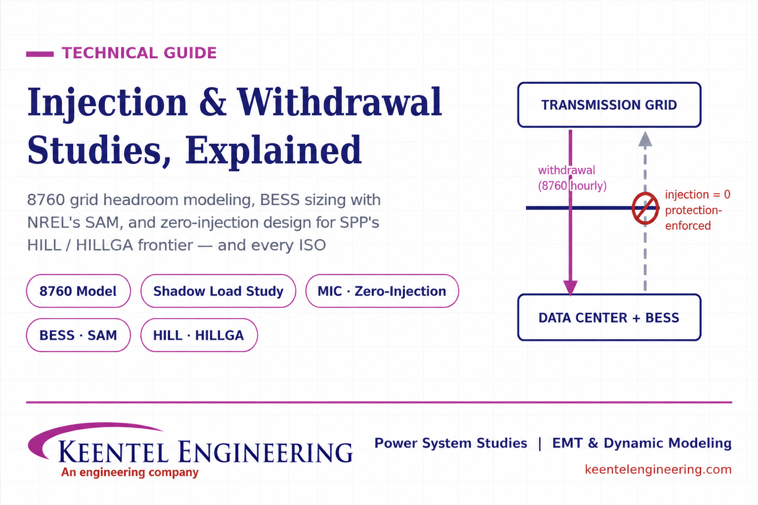
Learn how injection and withdrawal studies, 8760 headroom modeling, zero-injection engineering, and SPP HILLGA improve large load grid interconnections
By SANDIP R PATEL
•
July 21, 2026
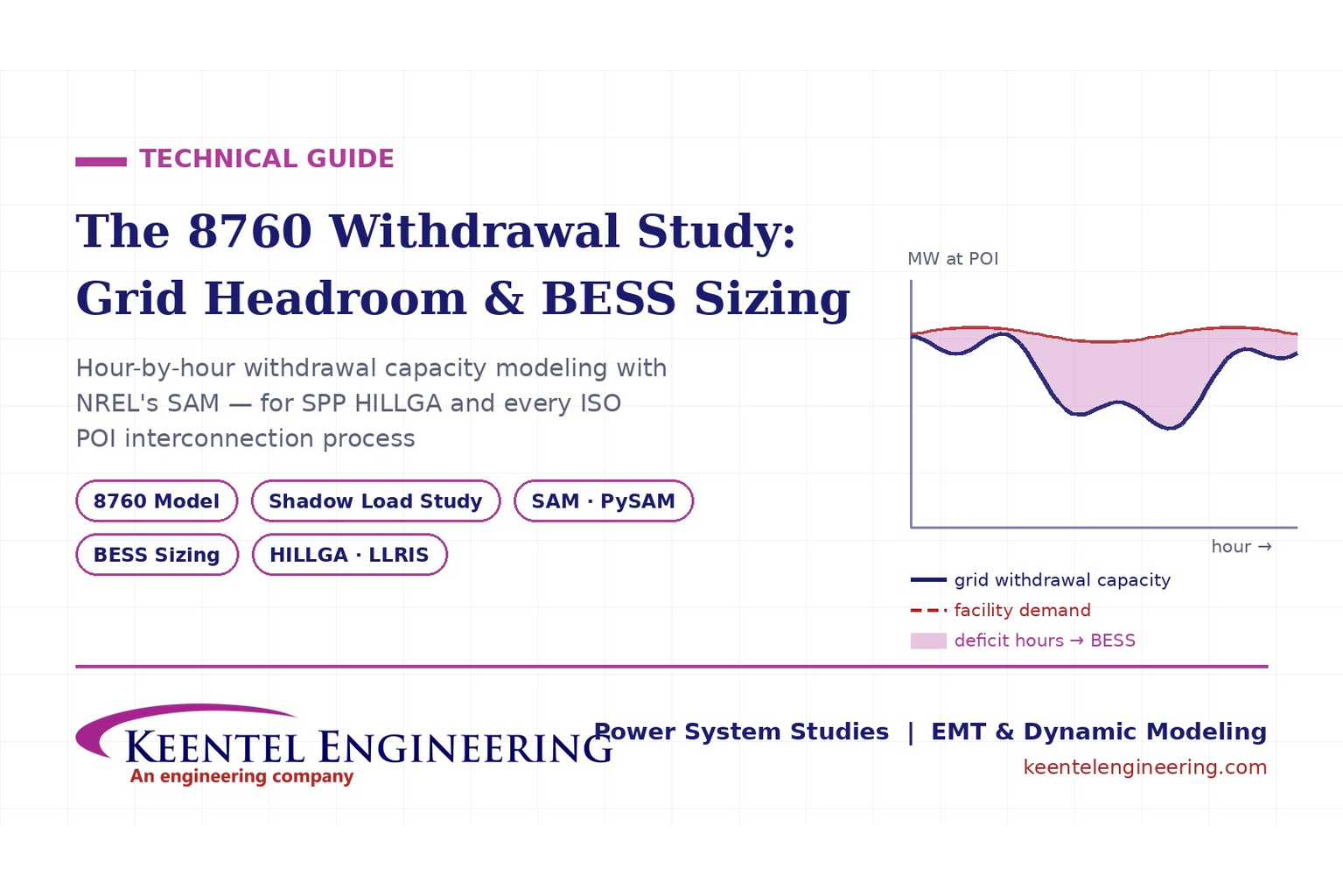
Learn how an 8760 withdrawal study models hourly grid headroom and uses SAM-based BESS sizing for large-load interconnection projects.
By SANDIP R PATEL
•
July 21, 2026
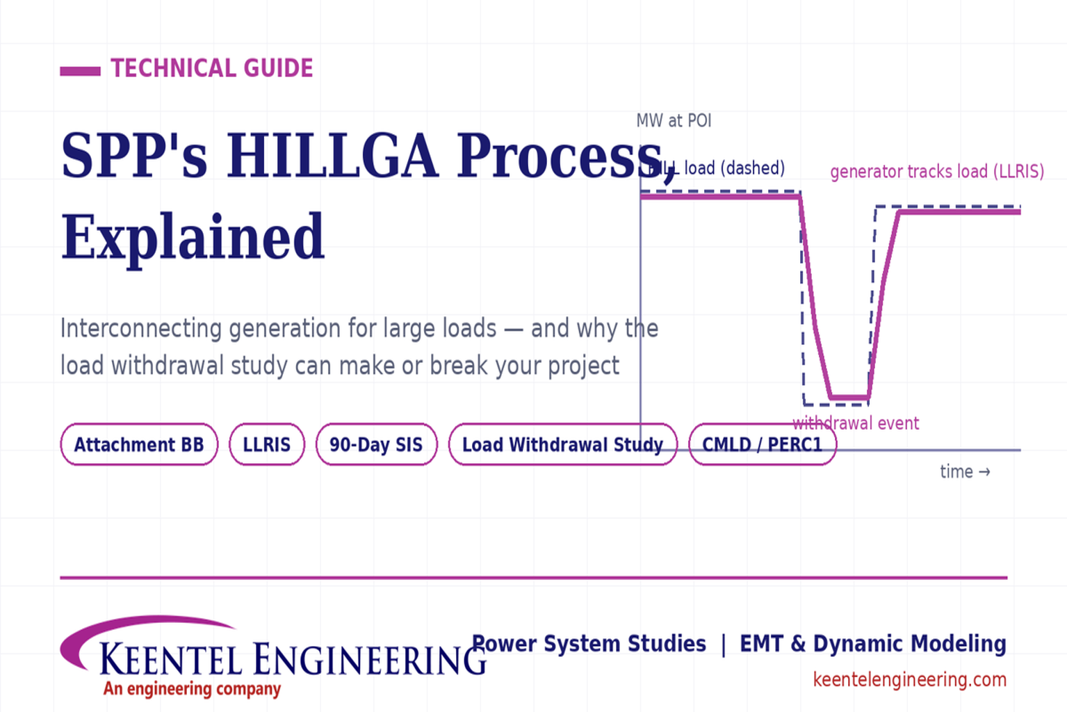
Learn how the SPP HILLGA process supports data center generation interconnection and why an 8760 withdrawal study can determine project success.
By SANDIP R PATEL
•
July 19, 2026
Learn electrical protection and relay coordination for hyperscale data centers with IEEE standards, short-circuit studies, arc-flash analysis, and MV protection.
By SANDIP R PATEL
•
July 18, 2026
Explore Battery Energy Storage System components, including cells, PCS, BMS, EMS, cooling, fire protection, sizing, safety, and grid codes.
By SANDIP R PATEL
•
July 18, 2026
Explore how grid-forming inverters support BESS, synthetic inertia, grid-code compliance, plant sizing, testing, and project revenue.
By SANDIP R PATEL
•
July 18, 2026
Learn how SEL RTAC protection monitoring supports NERC PRC-005 compliance, predictive maintenance alarms, automated reporting, and relay verification.
By SANDIP R PATEL
•
July 17, 2026
Explore utility-scale BESS design from the 10% package to IFC, NFPA 855 compliance, PSS®E/PSCAD models, and ERCOT interconnection.
By SANDIP R PATEL
•
July 17, 2026
Substation design guide, electrical substation design, substation equipment sizing, IEEE 80 grounding design, IEEE 998 lightning shielding, bus configuration design


