A Coordinated Electric System Interconnection Review—the utility’s deep-dive on technical and cost impacts of your project.
Challenge: Frequent false tripping using conventional electromechanical relays
Solution: SEL-487E integration with multi-terminal differential protection and dynamic inrush restraint
Result: 90% reduction in false trips, saving over $250,000 in downtime
| Category | Metric |
|---|---|
| VPP capacity (Lunar Energy) | 650 MW |
| Lunar funding raised | US$232 million |
| Data center BESS example | 31 MW / 62 MWh |
| ERCOT grid-scale batteries | 15+ GW |
| LDES tenders (H1 2026) | Up to 9.3 GW |
| Lithium-ion share of LDES by 2030 | 77% |
| FEOC initial threshold | 55% |
| BESS tariff rate (2026) | ~55% |
| Capacity gain from analytics | 5–15% |
What is T&D Co-Simulation?
Confusing Physical Connections with Logical Nodes in IEC 61850
ERCOT Short Circuit Case Building Procedure Manual v2.0 A Complete Technical Guide Prepared by Keentel Engineering
Jan 1, 2022 | blog
Understanding ERCOT's Short Circuit Case Building Process: A Keentel Engineering Deep Dive into Version 2.0
At Keentel Engineering, we work closely with transmission system operators, protection engineers, and grid planners navigating the complex requirements of ERCOT's annual short circuit case building process. This guide breaks down the ERCOT System Protection Working Group's (SPWG) Short Circuit Case Building Procedure Manual, Version 2.0 the most comprehensive update to date so your team has a clear, actionable reference for every stage of the workflow.
Background: Why Short Circuit Cases Matter
Short circuit base cases are the foundational models that determine how fault current flows through the ERCOT transmission system under abnormal conditions. These models directly inform relay settings, breaker ratings, protection coordination, and NERC compliance obligations. Getting them right is not optional — inaccurate models lead to under- or over-reaching relay operations, missed faults, or unnecessary tripping of healthy equipment.
ERCOT's SPWG builds these models annually in two categories: the Current Year (CY) case, representing the grid as expected on June 30th of the present year, and five Future Year (FY) cases covering CY+1 through CY+5. Every Transmission Service Provider (TSP) participates in this process, submitting incremental data changes that ERCOT compiles into the shared SPWG system case. The manual documents every step of that process in detail, and Version 2.0 introduces several critical updates that Keentel Engineering clients need to understand.
What's New in Version 2.0
Version 2.0 represents years of iterative refinement. Key additions and changes since earlier versions include a restructured introduction with an explicit SPWG scope statement, a completely redesigned file naming convention with cleaner two-digit year identifiers, migration of fault analysis from PSS/E to ASPEN OneLiner's native Bus Fault Summary tool, a new detailed modeling methodology section covering pre-fault voltages, wind and solar generation, transmission line data, transformer data, and tie line coordination, and an entirely new appendix on wind and solar aggregation techniques.
The SPWG's Organizational Mandate
Version 2.0 opens with a clearer statement of SPWG's organizational role than previous versions. The SPWG operates under the direction of ERCOT's Reliability and Operations Subcommittee (ROS) and is a non-voting working group whose members include representatives from all ERCOT TSPs and ERCOT staff. Three core responsibilities are defined: producing the CY base case by approximately April 1st each year, producing the FY base cases by approximately July 1st each year, and reviewing and updating the procedural manual at least every five years.
The manual is now explicitly framed as an instrument for demonstrating compliance with applicable NERC Reliability Standards. This is important context for Keentel Engineering clients who need to justify their modeling practices during audits or NERC reviews.
The Software Platform: ASPEN OneLiner Continues as the Standard
ASPEN OneLiner remains the mandated software platform for short circuit case building, with PSS/E continuing to serve as an acceptable submission format for TSPs that do not use ASPEN. For the 2021 case building cycle documented in Version 2.0, SPWG agreed on ASPEN v14.8 and PSS/E v33. The November SPWG meeting each year establishes the versions that all participants must use for the next cycle.
Short circuit models are bus-branch representations of the high-voltage
transmission system at 60 kV and above, encompassing buses, branches, impedances, reactive devices, transformers, generators, and DC lines. The system base is 100 MVA across all cases.
The New File Naming Convention: Cleaner and More Systematic
Version 2.0 introduces a significantly revised file naming convention that Keentel Engineering strongly recommends all clients adopt carefully. The old convention used full four-digit year identifiers for both the build year and the case year. The new convention uses a compact two-digit build year prefix combined with a four-digit target case year, along with explicit pass indicators and process stage suffixes.
The core components are: AAA (company acronym), BB (two-digit build year), SPWG (constant identifier), CCCC (four-digit target case year), XX (CY or FY), MMDDYYYY (posting date), and N (pass number or "Final").
A member submitting Future Year 2022 Pass 2 data during the 2021 build cycle would name their change file: AEP_21_SPWG_2022_FY_Pass2.CHFERCOT's consolidated change file for that same pass would be named:
21_SPWG_2022_FY_05212021_Pass2_consolidated.CHF Separate naming conventions apply to conversion logs, change file creation logs, consolidated change logs, import logs, and the final built case files. Each has a distinct suffix (_conversion_log.TXT, _change_log.TXT, _consolidated_log.TXT, _import_log.TXT) that distinguishes it from similarly-named files at different stages of the pipeline. Strict adherence is required — no alternative naming conventions are accepted by ERCOT.
Converting PSS/E to ASPEN: The DXT Conversion Workflow
For TSPs submitting in PSS/E format, ERCOT performs the conversion using the PTI PSS/E-ASPEN conversion utility included with ASPEN OneLiner, accessed via Program Files > ASPEN OneLiner > PTI PSS/E-ASPEN.
The most critical prerequisite is saving PSS/E RAW files using the "Configure RAW file to: Use with RDCH" option. Both the .raw and .seq files must be included submitting only the raw file produces an incomplete model missing all sequence impedance data. Conversion options used by ERCOT include converting loads, positive sequence shunts, transformer tap ratios, and transmission line shunts, treating 3-winding YYD transformer high-voltage sides as the primary bus, preserving out-of-service equipment, and setting line length units to miles.
After conversion, a detailed log is saved following the naming convention and distributed to SPWG members so that any conversion errors can be identified and corrected in the next pass.
The Change File Process: How Incremental Case Building Works
The ASPEN Change File (CHF) methodology is the engine of the entire case building process. Rather than rebuilding the entire system model from scratch each year as was done under PSS/E — ASPEN OneLiner builds cases incrementally. Only the differences from the prior case need to be submitted each pass.
The fundamental equation is: Base Case + Change File = Updated Case.
CHF files are created using the ASPEN Case Comparison program (Program Files > ASPEN OneLiner > Case Comparison). The user loads two files — File A (the base case) and File B (the updated case with the member's changes) — and the program generates a CHF capturing only the differences.
A key update in Version 2.0 is that comparison is now performed using "Name and kV" rather than Bus Number, because bus names and kV combinations are now considered reliably unique in the ERCOT system. TSPs should select only their own area using the "Inside" radio button, must check "Include ties between selected items and the rest of the network," and must exclude generator facilities in the +900 area offset range
The Future Year Case Build Process: A Detailed Look at the New Methodology
Version 2.0 provides a significantly more detailed and precise description of how future year Pass0 cases are constructed, and it is one of the most important updates for Keentel Engineering clients to understand.
The process works as follows for the 2021 build cycle. The FY Pass0 for the 2022 case year is built by starting from the prior year's 2022 FY Final Pass case (built in 2020, named 20_SPWG_2022_FY_FinalPass.DXT) and adding an incremental CHF that captures what changed between the prior 2021 FY Final Pass and the newly completed 2021 CY Final Pass. In other words, the "delta" between what was modeled for 2021 a year ago and what is now known to have happened in 2021 gets propagated forward into the 2022 base.
This same logic cascades through Y+2, Y+3, Y+4, and Y+5. Each future year's Pass0 is derived from the prior year's corresponding FY Final Pass, updated with the delta between its predecessor and the newly completed case. The Y+5 Pass0 is identical to the Y+4 Pass0. This carefully constructed chain of incremental updates means that every future year case accurately reflects the latest known information while minimizing manual rework.
Fault Analysis: Migrated to ASPEN's Bus Fault Summary
One of the most significant operational changes in Version 2.0 is the migration of fault analysis from PSS/E (which was used in v1.6 for TREE analysis, FLAT/CL, and IDV scripting) to ASPEN OneLiner's native Bus Fault Summary tool.
After completing the case build and exporting PSS/E files, the user returns to ASPEN OneLiner and runs Bus Fault Summary via Menu > Faults > Bus Fault Summary. The "Exclude tap buses" checkbox must be unchecked before running. The output is a CSV file named following the standard convention with a _Bus_Fault_Summary.csv suffix.
As a quality check, the SPWG case currently contains over 12,000 buses. If the total bus count in the output deviates significantly from this, the run should be cancelled and restarted with careful attention to the tap bus exclusion setting.
Fault comparison across passes and years follows the same logic as in prior versions: current year data is compared against that same year's data from the prior year's final future year pass, while future year data is compared year-over-year and pass-over-pass to track trends.
Modeling Methodologies: The New Section That Changes Everything
Version 2.0 introduces a dedicated Modeling Methodologies section (Section 3) that did not exist in prior versions. This section is essential reading for protection engineers and is where Keentel Engineering sees the most significant practical impact for our clients.
Pre-fault Voltage:
ASPEN uses a linear network solution where pre-fault bus voltages are calculated using a matrix form of Ohm's law. ERCOT obtains generator reference voltages and angles from the SSWG (Steady State Working Group) summer peak case for the relevant year and enters them into the ref.V and ref.Ang fields in the SPWG cases.
Generator Data RARF Translation:
The RARF-to-ASPEN mapping table is updated in Version 2.0 to include two new parameters for current-limited generators (wind and solar turbine types 3 and 4): Current Limit A (instantaneous controlled fault current magnitude, in multiples of full load current) and Current Limit B (controlled fault current magnitude at 4+ cycles after fault, also in multiples of full load current). These additions reflect the growing penetration of renewable generation in the ERCOT system.
Wind and Solar Modeling:
This is an entirely new and critically important section. Wind turbines and solar plants are connected through inverters that do not behave like synchronous machines during fault conditions. ASPEN recommends modeling them as current-limited generators. Type-4 wind turbines and solar PV plants initially produce roughly 2.5 times full-load current during a fault, settling to 1.1–1.2 times full-load current within a few cycles. Their zero sequence impedance is set to j999 pu to prevent zero sequence current contribution. ASPEN also recommends setting negative sequence impedance to j999 in most cases, though this is a point of ongoing discussion given its effect on terminal voltage.
Type-3 wind turbines are more complex they are doubly-fed machines that can act either as inverter-controlled or as induction machines depending on whether the crowbar protection has activated. Protection studies for Type-3 WTGs should examine both scenarios: with and without current limits active.
Transmission Line Data:
Line impedance data must be entered as per-unit values on the nominal kV base, covering positive sequence (with shunt susceptance) and zero sequence (with shunt susceptance). Negative sequence is assumed equal to positive sequence and is not explicitly entered.
Mutual Impedance:
The mutual impedance guidelines remain consistent with prior versions — circuits sharing structures or ROW narrower than 100 feet require mutual impedance modeling when coupled length exceeds 10% of the shortest circuit or when mutual impedance exceeds 10% of the smallest zero-sequence impedance.
Tie Line Coordination:
A new subsection details the specific parameters that neighboring TSPs must coordinate for every tie line: in-service/out-of-service dates, from bus and to bus numbers, circuit identifier, impedance, mutual impedance, LTC transformer adjustment data, branch status, circuit miles, ownership (up to four owners), and the entity responsible for data submission.
Transformer Data:
Version 2.0 provides detailed guidelines for both 2-winding and 3-winding transformer data entry in ASPEN OneLiner. All existing windings must be modeled, including unloaded tertiary windings, since zero sequence current paths depend on winding configuration. Test report data is the required source for impedance values. Transformer data must comply with NERC MOD-32-1 Attachment 1.
Wind and Solar Aggregation: New Appendix A
Appendix A is an entirely new addition providing technical guidance on how to aggregate wind and solar plant models from either detailed ASPEN models or RARF data. The aggregation formula for padmount transformers combines complex impedance with the number of transformers and a base conversion factor. Generator units are aggregated by keeping per-unit impedances constant (they don't change with aggregation) while multiplying the Unit Rating MVA by the number of units. When a detailed ASPEN model is provided by a generator owner, it must be validated against the RARF data for consistency.
The Final Output Package
Each completed pass produces a comprehensive package for SPWG review. ASPEN files include the *.OLR case file, all member-submitted CHF files with their import logs, and all CHF files converted from PSS/E. PSS/E files include the *.raw, *.seq, and *.sav files. Excel reports include the Bus Fault Summary CSV, a Bus Comparison Excel file, a Generation Modeling Excel file, a Nearest Generator Report, and a TSP Response file. This expanded set of Excel reports (compared to prior versions) reflects ERCOT's enhanced data validation workflow.
15 Detailed FAQs Keentel Engineering Reference Guide
Q1. What is the SPWG and what authority does it operate under in the ERCOT system?
The System Protection Working Group (SPWG) is a non-voting technical working group that operates under the direction of ERCOT's Reliability and Operations Subcommittee (ROS). Its membership includes representatives from all ERCOT Transmission Service Providers and ERCOT staff. The SPWG's primary responsibilities related to short circuit case building are threefold: producing the Current Year (CY) short circuit base case by approximately April 1st each year, producing the five Future Year (FY) short circuit base cases by approximately July 1st each year, and reviewing and updating the procedural manual at least once every five years. Version 2.0 explicitly states that the procedure manual is intended to demonstrate compliance with applicable NERC Reliability Standards, meaning the SPWG's work is directly linked to ERCOT's NERC compliance obligations. For Keentel Engineering clients subject to NERC MOD standards, participation in the SPWG process and adherence to this manual is part of demonstrating standards compliance.
Q2. How does the new Version 2.0 file naming convention differ from previous versions, and why does it matter?
The Version 2.0 naming convention represents a significant structural overhaul. The most visible change is the introduction of a two-digit build year prefix (BB) in front of the SPWG identifier, replacing the older pattern that embedded the full year only once. For example, a change file in the old convention might read AEP_2012_FY_Pass2.CHF; in the new convention, the same type of file for the 2021 build cycle targeting 2022 reads AEP_21_SPWG_2022_FY_Pass2.CHF. This dual-year encoding (BB for the build year, CCCC for the target case year) makes it unambiguous both when the file was produced and what case year it pertains to. Additionally, consolidated files — a new category in Version 2.0 — have their own naming convention with a _consolidated suffix. Different log types also now carry distinct suffixes: _conversion_log, _change_log, _consolidated_log, and _import_log. These distinctions are essential because multiple similarly-purposed files are generated during a single pass, and without precise naming, files can be confused, overwritten, or misapplied during compilation. ERCOT accepts no alternative naming conventions, so clients should update any automated scripts or submission workflows to reflect the new standard.
Q3. What cases are built each year and what conditions must each one reflect?
Each annual SPWG case building cycle produces six cases: one Current Year (CY) and five Future Year (FY) cases covering CY+1 through CY+5. Each case must reflect the expected network configuration as of June 30th of that case year, meaning all equipment reasonably expected to be in service by June 30th must be included and modeled as in-service. Generators must meet the requirements of ERCOT Planning Guide Section 6 to be included in the appropriate case year. Mutual impedance effects must be reflected per Section 3.5 guidelines. The system base is 100 MVA across all cases. The CY case is typically finalized by end of March, and the FY cases are typically finalized by end of June, though the SPWG and ERCOT set the specific schedule annually. For Keentel Engineering clients planning capital projects, this June 30th cutoff date determines which construction milestones need to be reflected in which case year, making it a critical planning parameter for interconnection studies and protection upgrade projects.
Q4. How does the Future Year Pass0 case building process work in Version 2.0, and why is it more complex than the Current Year process?
The Future Year Pass0 process is the most architecturally sophisticated part of the case building workflow and was significantly clarified in Version 2.0. The key insight is that each FY Pass0 case is not built from scratch but is derived from the prior year's FY Final Pass case for that same target year, updated with an incremental change file that captures what changed in the most recently completed case year. For example, building the 2022 FY Pass0 during the 2021 case build cycle starts with 20_SPWG_2022_FY_FinalPass (built a year ago) and adds a change file representing the difference between 20_SPWG_2021_FY_FinalPass (2021 as it was modeled last year) and 21_SPWG_2021_CY_FinalPass (2021 as it is now modeled with current-year accuracy). This delta propagation cascades through Y+2, Y+3, Y+4, and Y+5 in a chain, with each year's Pass0 incorporating the delta from its predecessor. The Y+5 Pass0 is simply copied from the Y+4 Pass0. This structure is more complex than the CY process — which straightforwardly takes the prior CY Final Pass and applies incremental updates — but it ensures that future year cases always reflect the latest confirmed information without losing continuity from the prior cycle.
Q5. What changed in how ASPEN Change Files are created using the Case Comparison tool in Version 2.0?
The most notable change in CHF creation procedure between Version 1.6 and Version 2.0 is the correlation method. Version 1.6 specified comparing by Bus Number, noting that bus names may not be unique. Version 2.0 reverses this, specifying that comparison should be performed using "Name and kV" because bus names and kV combinations are now treated as reliably unique within the ERCOT system. This change reflects improvements in ERCOT's bus naming standards over time. All other key settings remain consistent: the "Inside" radio button must be used with the TSP's own area numbers; generator facilities in +900 offset areas must be excluded from the change file; and the "Include ties between selected items and the rest of the network" checkbox must be checked. ASPEN users create their own CHF files and submit them to ERCOT. Non-ASPEN users who submit in PSS/E have their CHF files created by ERCOT on their behalf. All CHF files and their corresponding change logs must be sent to ERCOT for screening before being run in the next pass build.
Q6. How is fault analysis performed in Version 2.0, and how does this differ from the PSS/E-based approach in Version 1.6?
This is one of the most operationally significant changes in Version 2.0. Version 1.6 performed fault analysis in PSS/E using the TREE command (to identify and disconnect electrical islands), the FLAT, CL command (to initialize the case for fault calculations), and an IDV scripting file (checkascc_revised_01192010.idv) to generate fault current data files. Version 2.0 replaces this entire PSS/E workflow with ASPEN OneLiner's native Bus Fault Summary tool, accessed via Menu > Faults > Bus Fault Summary. After the case build and PSS/E export are complete, the engineer returns to ASPEN OneLiner, opens the Bus Fault Summary window, unchecks "Exclude tap buses," and runs the analysis. The output is a CSV file. As a validation step, the total bus count should be verified against the known SPWG case count of 12,000+ buses — a significant discrepancy indicates the tap bus exclusion setting was applied incorrectly. This migration to ASPEN-native fault analysis simplifies the workflow, eliminates dependency on PSS/E CLI commands, and provides a directly usable CSV output without the intermediate scripting steps required in the old workflow.
Q7. How should wind turbine generators (WTGs) be modeled in ASPEN OneLiner, and what is the difference between Type-3 and Type-4 machines?
Version 2.0 dedicates a full subsection to renewable generation modeling, reflecting the dramatic growth of wind and solar in ERCOT. Both Type-3 and Type-4 WTGs, as well as solar PV generators, are modeled as current-limited generators rather than conventional synchronous machines, because their inverter-based connection to the grid produces fundamentally different fault behavior. For Type-4 WTGs and solar PV, the zero sequence impedance is set to j999 pu to prevent zero sequence current contribution (these machines are ungrounded). Positive sequence impedance is set to j0.02 pu — notably, this is not the machine's actual impedance but a modeling approximation. ASPEN also recommends setting negative sequence impedance to j999 in most cases. Current Limit A represents instantaneous fault current (approximately 2.5x full load), while Current Limit B represents steady-state fault current at 4+ cycles (approximately 1.1–1.2x full load). For protection studies, Current Limit B is typically more useful. Type-3 WTGs are more complex because they are doubly-fed machines — a hybrid between synchronous and induction designs. During close-in faults, Type-3 machines may activate their crowbar protection, at which point they behave as induction machines. Protection studies must therefore examine Type-3 behavior both with and without current limits. When crowbar is active, Current Limit A should be set to zero to disable it. The zero sequence impedance for Type-3 is also set to j999, but positive sequence impedance should reflect the machine's actual transient or subtransient impedance.
Q8. How is RARF generator data translated into ASPEN OneLiner, and what new parameters were added in Version 2.0?
The RARF-to-ASPEN parameter mapping table was expanded in Version 2.0 to include two new entries relevant to current-limited generators. The established parameters remain unchanged: MVA Base maps to Unit Rating (MVA); saturated subtransient reactance X''dv maps to Subtransient (jX); saturated transient reactance X'dv maps to Transient (jX); saturated synchronous reactance Xdv maps to Synchronous (jX); saturated negative sequence reactance X2v maps to negative sequence (jX); saturated zero sequence reactance X0v maps to zero sequence (jX); armature positive sequence resistance R1 maps to the R component of Subtransient, Transient, and Synchronous simultaneously; R2 maps to negative sequence (R); and R0 maps to zero sequence (R). The two new entries are: Instantaneous Controlled Fault Current Magnitude (parameter A, in multiples of full load current) for turbine Types 3 and 4, which maps to Current Limit A in ASPEN; and Controlled Fault Current Magnitude at 4+ cycles after fault (parameter B, also in multiples of full load current) for turbine Types 3 and 4, which maps to Current Limit B. All values use saturated impedances on a per-unit basis at the unit MVA base. For current-limited generators, saturated values are replaced by the current limit values from the RARF.
Q9. What are the requirements for modeling transmission line and branch data in the SPWG case?
Version 2.0's new Transmission Line or Branch Data section specifies that line impedance data must be calculated based on the TSP's own engineering criteria and entered as per-unit values on the nominal kV base. Positive sequence parameters must include both impedance and shunt susceptance where applicable. Negative sequence parameters are assumed equal to positive sequence and are not explicitly entered into the short circuit case. Zero sequence parameters must include both impedance and shunt susceptance where applicable. Zero sequence data is particularly important because it directly governs the magnitude of ground fault currents, which determine ground relay pickup settings and are sensitive to the physical line geometry and grounding configuration. ASPEN OneLiner's line data entry screen captures R, X, B (positive sequence) and R0, X0, B0 (zero sequence), along with circuit miles for mutual impedance calculations. For Keentel Engineering clients with new line projects, ensuring that both positive and zero sequence line constants are accurately calculated from conductor data, tower geometry, and ground wire configuration — and properly entered in per-unit — is essential before submission.
Q10. What are the tie line coordination requirements, and why is this particularly important for protection engineers?
Version 2.0 adds a dedicated tie line coordination section that formalizes the parameters neighboring TSPs must agree on for every shared facility. A tie line is defined as any transmission circuit with multiple owners represented within the associated facility context. The parameters requiring explicit coordination include in-service and out-of-service dates, from bus number, to bus number, circuit identifier, impedance, mutual impedance, LTC transformer adjustment data, branch status, circuit miles, ownership (up to four owners), and the entity responsible for submitting the data. The manual emphasizes that even when no new tie lines are added to the network, existing tie line data can still change due to construction timing changes, modeling refinements, or ownership transitions. Coordination must happen early enough to allow CY and FY work to proceed without delays. For Keentel Engineering clients near TSP boundaries, tie line data discrepancies are among the most common sources of errors in compiled SPWG cases. The correction timeline is limited to the pass cycle, so unresolved tie line issues can persist through multiple passes if not addressed proactively.
Q11. What are the mutual impedance modeling thresholds, and how is responsibility assigned when two TSPs are involved?
Mutual impedance must be modeled in two scenarios, each with two alternative triggering thresholds. For circuits sharing a common physical structure (same towers or poles), mutual impedance must be included if either the coupled length exceeds 10% of the shortest line circuit, or the mutual impedance value exceeds 10% of the smallest zero-sequence impedance. For circuits sharing a common right-of-way narrower than 100 feet (but not necessarily on common structures), the same dual thresholds apply. Either threshold alone is sufficient to require modeling — both conditions do not need to be met simultaneously. TSPs may choose to model certain circuits in greater detail than these minimum thresholds require. When the mutually coupled circuits are owned or operated by different TSPs, those two TSPs must reach a bilateral agreement on which entity will submit the Mutual Pair data in ASPEN OneLiner. The responsible entity must document their identity in the Memo field of the ASPEN Mutual Pair entry. This documentation is important for data governance: if an error is found in the mutual pair data during review, it is immediately clear which TSP is responsible for the correction and resubmission.
Q12. How are transformer data requirements specified in Version 2.0, and what is the significance of zero sequence modeling for three-winding transformers?
Version 2.0 provides detailed transformer data entry guidelines for both 2-winding and 3-winding configurations. Transformer impedance data must come from manufacturer test reports whenever available; if no test report exists for an older unit, the TSP must document the rationale used to determine parameter values. All windings must be modeled regardless of whether they carry load — this is especially important for tertiary windings, which often carry no load but provide zero sequence current paths critical for ground fault calculations. For 2-winding transformers, the R, X, R0, and X0 values come directly from test report data. The magnetizing susceptances B and B0 are rarely required in short circuit calculations. Tap values must match the actual voltage from which impedance was determined, which may differ from the bus nominal voltage or the in-service tap position. LTC and metered-at fields are not used in short circuit analysis. For 3-winding transformers, the winding-pair impedances Zps, Zpt, Zst, and their zero sequence counterparts must be populated from test data. Grounding impedances Zg1, Zg2, and Zgn apply only when external grounding impedances are physically present. All transformer data must comply with NERC MOD-32-1 Attachment 1. For Keentel Engineering clients with aging transformer fleets lacking test reports, developing defensible parameter estimates consistent with MOD-32-1 is a frequent engineering need.
Q13. How does the wind and solar aggregation methodology work, and when should it be used instead of a detailed model?
Appendix A of Version 2.0 introduces a formal aggregation methodology for wind and solar plants, applicable when either a detailed ASPEN model is not available from the generator or when simplification is appropriate. The aggregation approach handles padmount transformers and generating units separately. For padmount transformers, the aggregate complex impedance is calculated as the single-transformer impedance divided by the number of turbines (N), scaled by the ratio of the new MVA base to the transformer's own MVA base. When the new MVA base is set equal to N times the transformer MVA base, the scaling factor becomes 1 and the aggregate impedance equals the single-transformer impedance — a convenient simplification. For generating units, per-unit impedances do not change with aggregation since they are already expressed in per-unit at the unit MVA base. The aggregate model simply uses a Unit Rating equal to the individual unit MVA multiplied by the number of units. MW, MVAR, and limit values scale proportionally. When a generator provides a detailed ASPEN model, it must be cross-validated against the RARF data to ensure consistency — the two data sources should be congruent, and discrepancies must be resolved before submission.
Q14. What is the pre-fault voltage methodology in Version 2.0, and how does it affect fault current calculations?
Version 2.0 introduces an explicit pre-fault voltage methodology that was not addressed in prior versions. ASPEN OneLiner uses a linear network solution where pre-fault bus voltages are calculated using a matrix form of Ohm's law that accounts for all network elements simultaneously. Rather than using a flat 1.0 per-unit voltage profile, ERCOT obtains actual generator bus voltages and angles from the SSWG (Steady State Working Group) summer peak case for the relevant case year and enters them into the ref.V (reference voltage) and ref.Ang (reference angle) fields in the SPWG case files. For example, to build the 2021 FY Pass0 case, ERCOT uses generator reference data from the 2021 SSWG summer peak case. Pre-fault voltage affects fault current magnitude because the fault current for a bolted fault is directly proportional to the pre-fault voltage at the fault bus. Using realistic pre-fault voltages rather than flat voltages provides more accurate fault current estimates at buses with significant voltage deviation from nominal, which is particularly relevant near large generation pockets or at the end of heavily loaded transmission paths. For Keentel Engineering protection studies, this means that SPWG cases may show modestly different fault current results at voltage-stressed buses compared to a flat-voltage baseline model.
Q15. What is the complete set of output files distributed to SPWG members after each pass, and how does it differ from prior versions?
The Version 2.0 output package is notably expanded compared to Version 1.6, reflecting ERCOT's enhanced data validation and reporting workflows. ASPEN files include the master *.OLR case file (named using the BB_SPWG_CCCC_XX_MMDDYYYY_PassN convention), all member-submitted CHF files with their corresponding import logs, and all CHF files that ERCOT converted from PSS/E submissions. PSS/E files include the *.raw network data file, *.seq sequence data file, and *.sav saved case file. Excel and CSV reports include five distinct files: the Bus Fault Summary CSV (containing raw fault current data for all buses), the Bus Comparison Excel file (which compares current and future year fault levels), the Generation Modeling Excel file (documenting generator data and modeling status), the Nearest Generator Report Excel file (identifying the closest modeled generator to each bus for protection study reference), and the TSP Response Excel file (used for tracking data queries and responses between ERCOT and TSPs). Compared to Version 1.6, which included only a fault comparison Excel spreadsheet and island data file, the Version 2.0 output suite provides substantially more data for verification. Keentel Engineering recommends that TSPs review all five Excel reports carefully after each pass, not only the Bus Fault Summary, as discrepancies often appear in generator modeling or tie line data before they become visible as fault current anomalies.
This technical guide was prepared by Keentel Engineering to support ERCOT TSPs, protection engineers, and grid planners in understanding and implementing the SPWG Short Circuit Case Building Procedure Manual Version 2.0. For questions about case submissions, ASPEN modeling, relay coordination studies, or NERC compliance documentation, contact Keentel Engineering's Power Systems Protection team

About the Author:
Sonny Patel P.E. EC
IEEE Senior Member
In 1995, Sandip (Sonny) R. Patel earned his Electrical Engineering degree from the University of Illinois, specializing in Electrical Engineering . But degrees don’t build legacies—action does. For three decades, he’s been shaping the future of engineering, not just as a licensed Professional Engineer across multiple states (Florida, California, New York, West Virginia, and Minnesota), but as a doer. A builder. A leader. Not just an engineer. A Licensed Electrical Contractor in Florida with an Unlimited EC license. Not just an executive. The founder and CEO of KEENTEL LLC—where expertise meets execution. Three decades. Multiple states. Endless impact.
Services

Let's Discuss Your Project
Let's book a call to discuss your electrical engineering project that we can help you with.
About the Author:
Sonny Patel P.E. EC
IEEE Senior Member
In 1995, Sandip (Sonny) R. Patel earned his Electrical Engineering degree from the University of Illinois, specializing in Electrical Engineering . But degrees don’t build legacies—action does. For three decades, he’s been shaping the future of engineering, not just as a licensed Professional Engineer across multiple states (Florida, California, New York, West Virginia, and Minnesota), but as a doer. A builder. A leader. Not just an engineer. A Licensed Electrical Contractor in Florida with an Unlimited EC license. Not just an executive. The founder and CEO of KEENTEL LLC—where expertise meets execution. Three decades. Multiple states. Endless impact.
Leave a Comment
Thank you for contacting us.
We will get back to you as soon as possible.
We will get back to you as soon as possible.
Oops, there was an error sending your message.
Please try again later.
Please try again later.
Related Posts
By SANDIP R PATEL
•
July 28, 2026
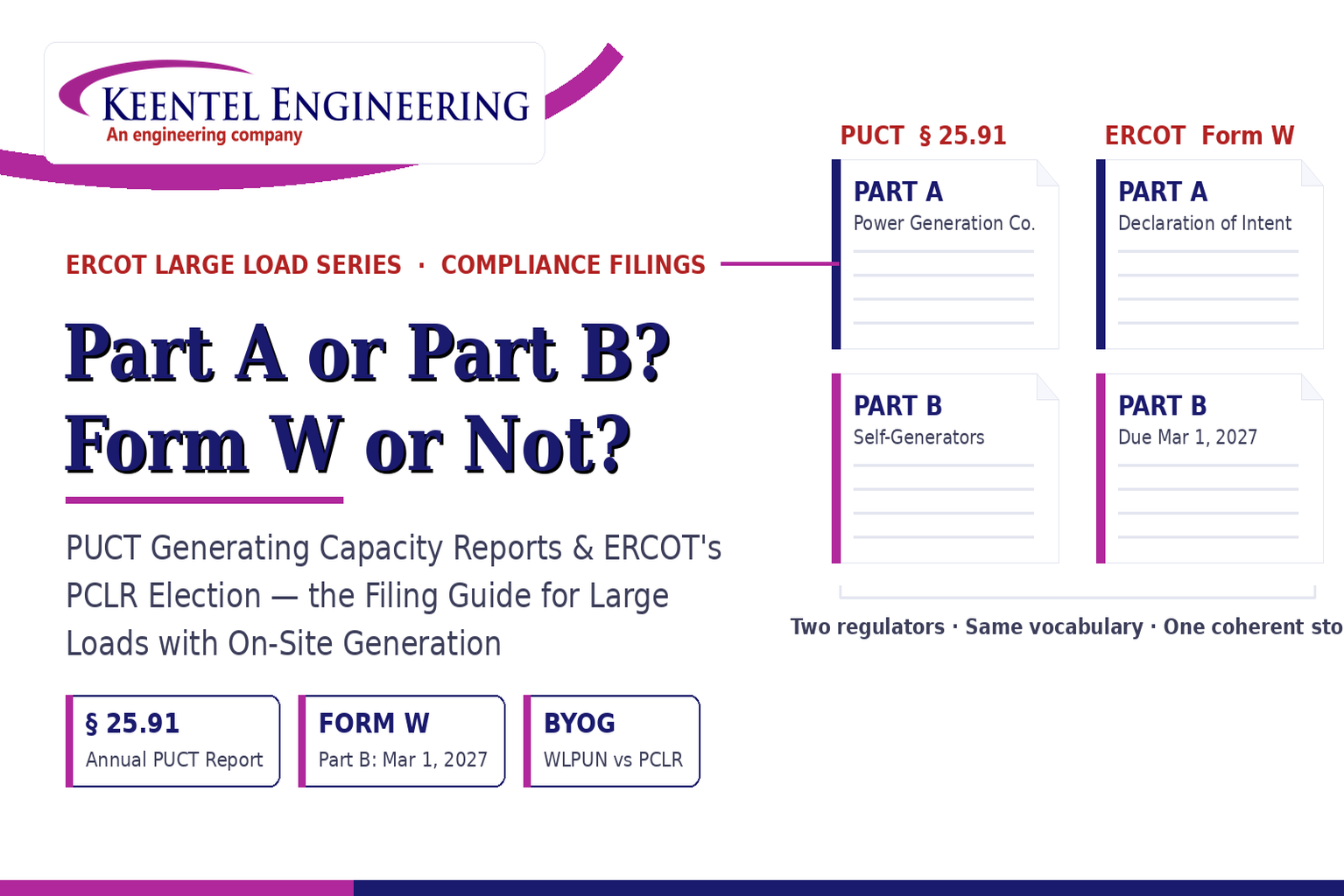
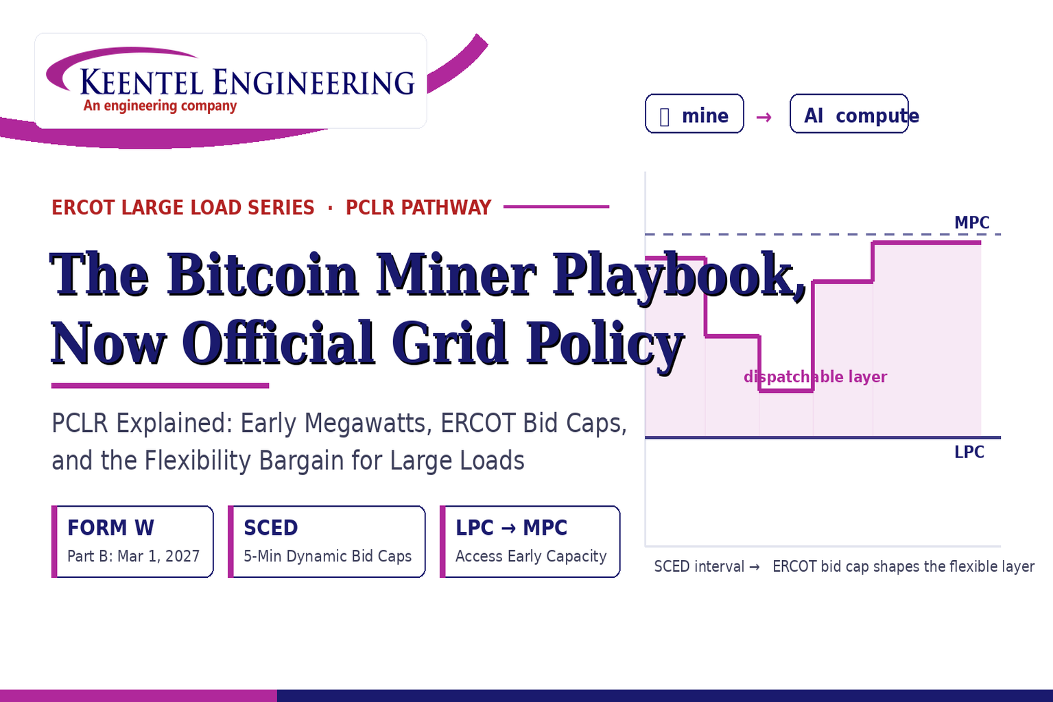
Learn the differences between the PUCT Generating Capacity Report and ERCOT Form W, including Part A vs Part B, PCLR, WLPUN, BYOG projects, and Batch Zero compliance.
By SANDIP R PATEL
•
July 28, 2026
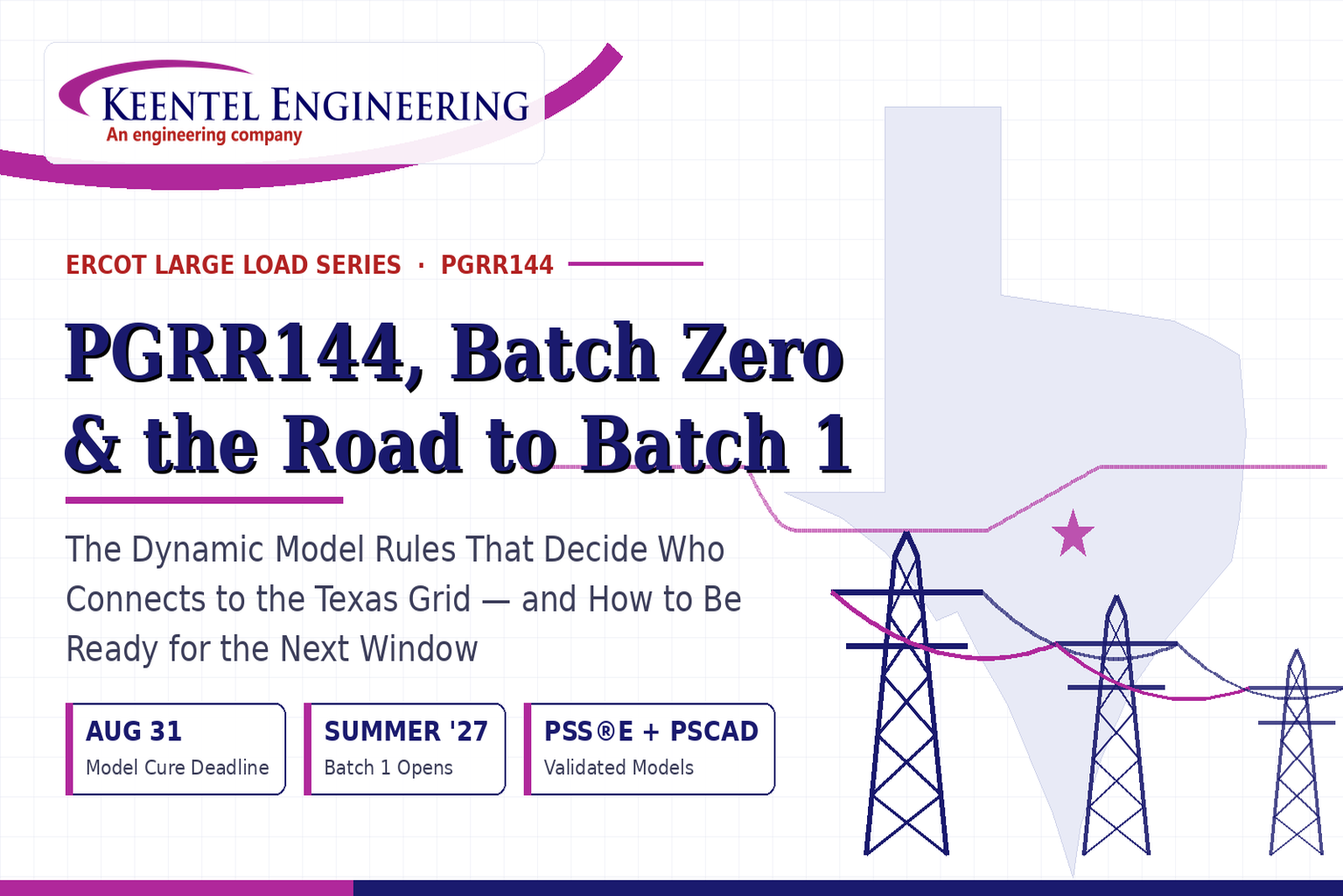
Learn how PGRR144, Batch Zero, and Batch 1 affect ERCOT large-load interconnections, dynamic model requirements, MQT testing, PERC1, and project readiness.
By SANDIP R PATEL
•
July 28, 2026
ERCOT PCLR Batch Zero large-load interconnection pathway
By SANDIP R PATEL
•
July 27, 2026
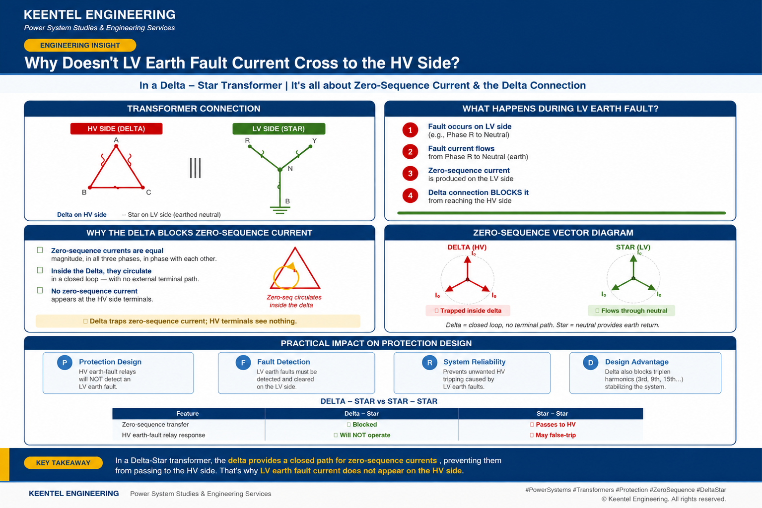
Learn why LV earth-fault current cannot cross a Delta-Star transformer, how zero-sequence current behaves, and what it means for protection design.
By SANDIP R PATEL
•
July 27, 2026
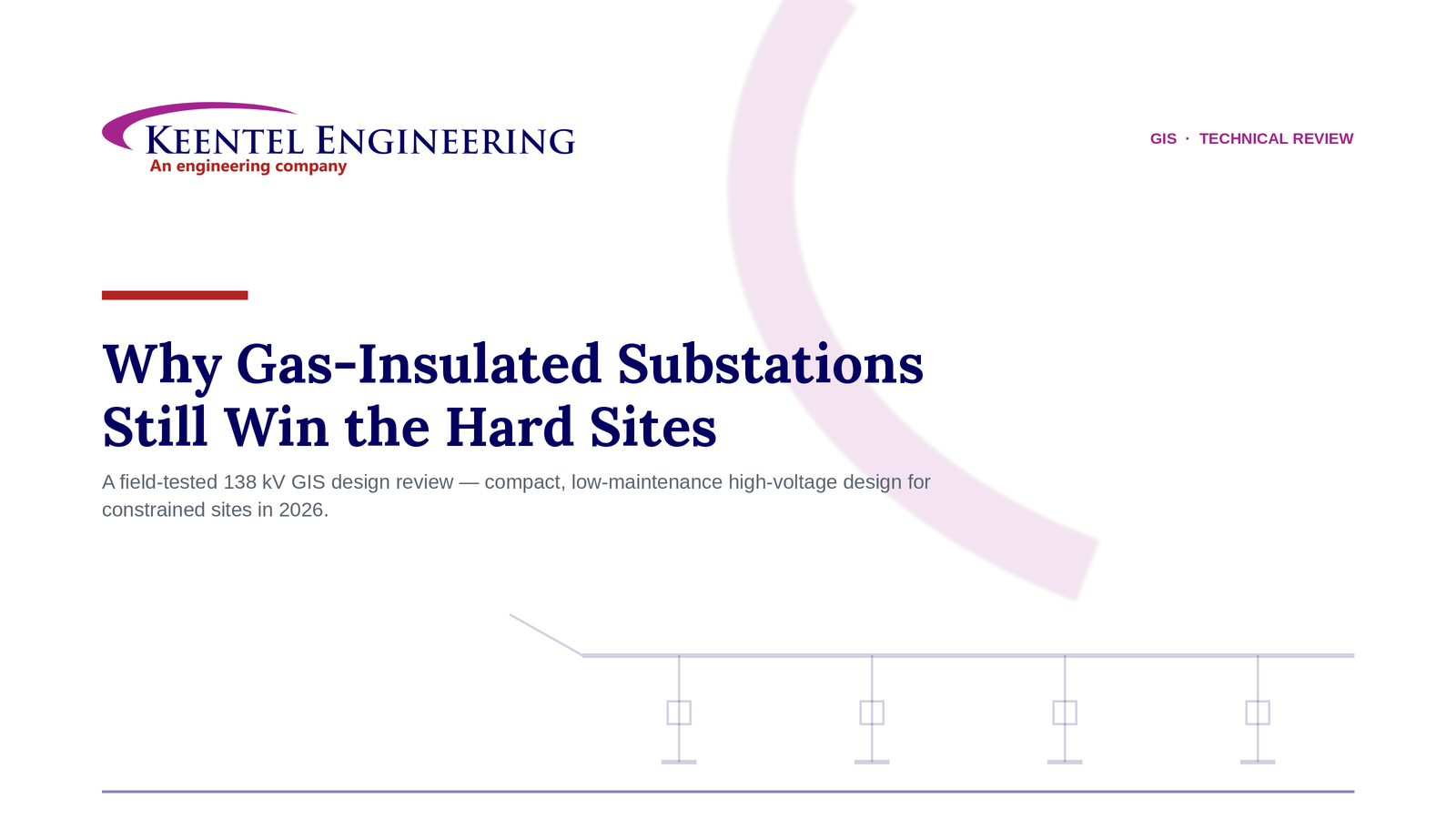
Learn how gas-insulated substations (GIS) improve safety, reliability, and space efficiency with 138 kV design, protection, insulation coordination, and real-world case studies.

By SANDIP R PATEL
•
July 25, 2026
Learn how Class I–IV electrical systems, defence-in-depth, standby and emergency power, DC systems, protection, and load transfer ensure nuclear power plant safety.
By SANDIP R PATEL
•
July 24, 2026
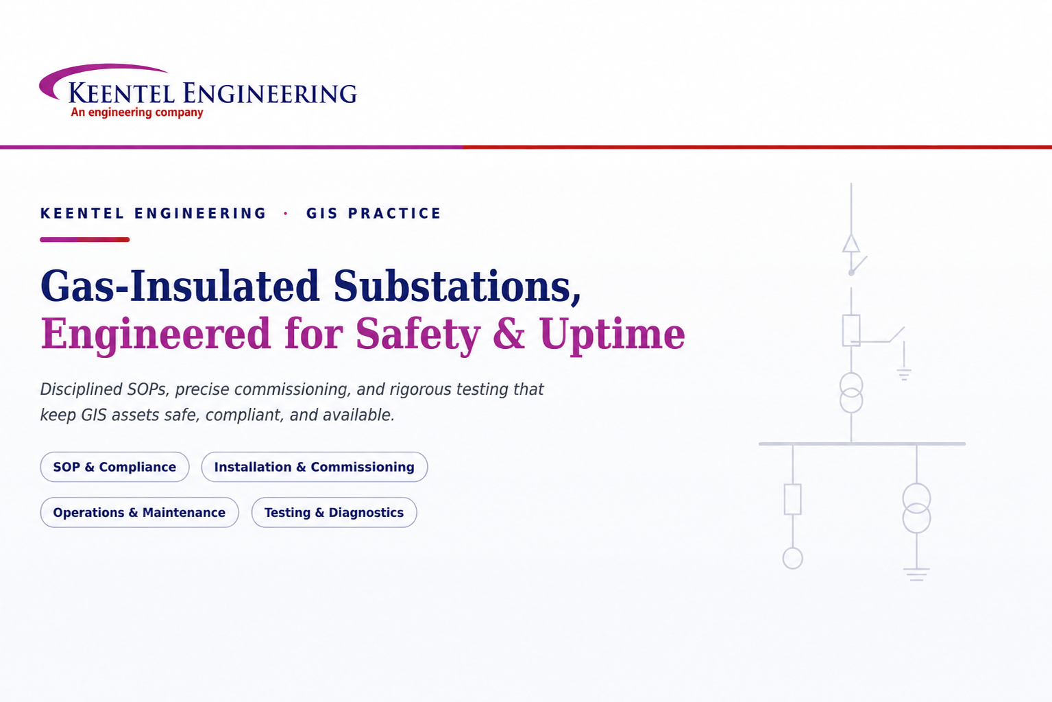
Learn GIS substation safety best practices, SOPs, commissioning, maintenance, interlocking, earthing, and testing to improve grid reliability and uptime.
By SANDIP R PATEL
•
July 23, 2026
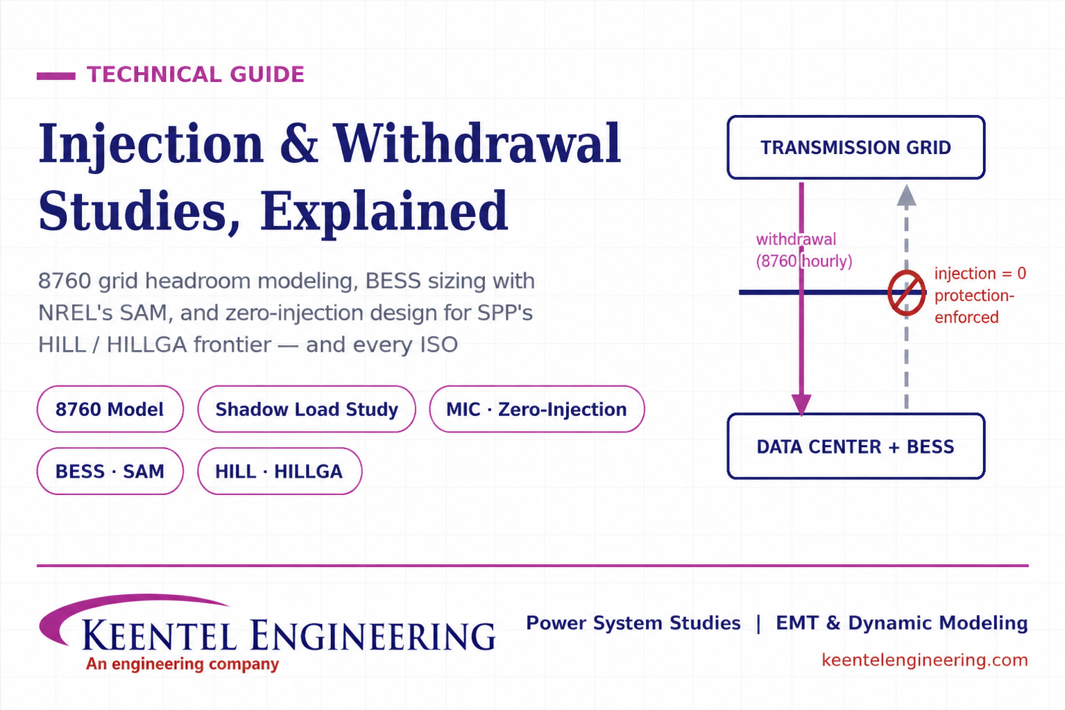
Learn how injection and withdrawal studies, 8760 headroom modeling, zero-injection engineering, and SPP HILLGA improve large load grid interconnections
By SANDIP R PATEL
•
July 21, 2026
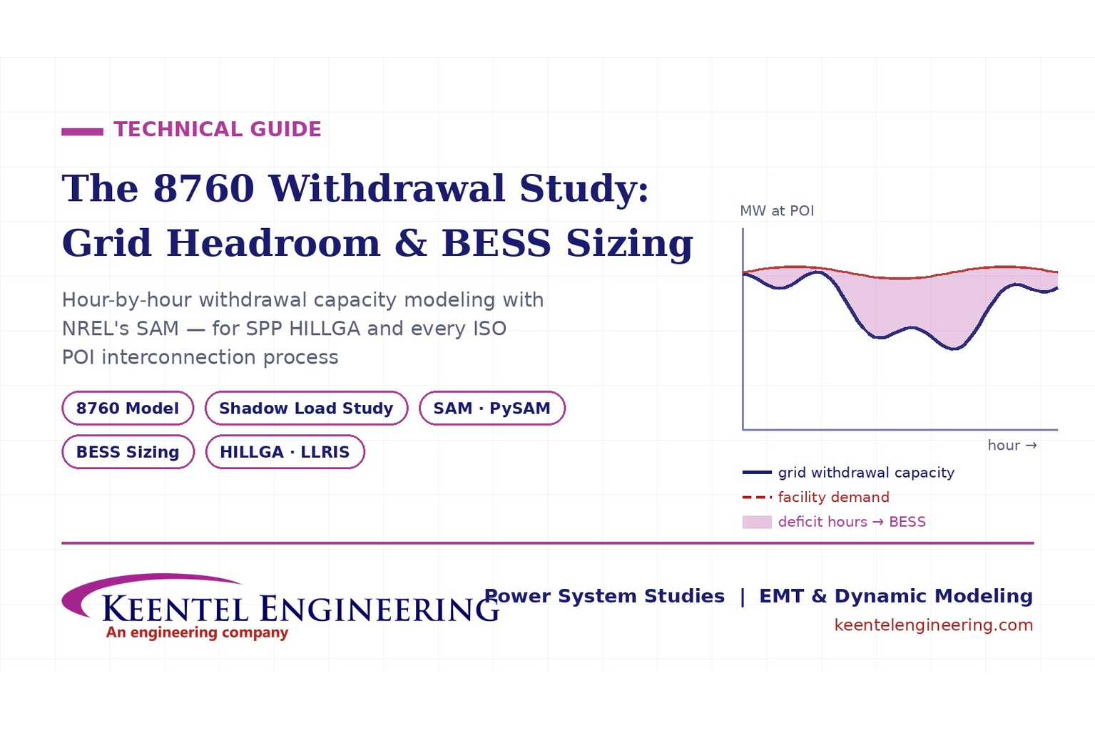
Learn how an 8760 withdrawal study models hourly grid headroom and uses SAM-based BESS sizing for large-load interconnection projects.