
A Coordinated Electric System Interconnection Review—the utility’s deep-dive on technical and cost impacts of your project.
Challenge: Frequent false tripping using conventional electromechanical relays
Solution: SEL-487E integration with multi-terminal differential protection and dynamic inrush restraint
Result: 90% reduction in false trips, saving over $250,000 in downtime
| Category | Metric |
|---|---|
| VPP capacity (Lunar Energy) | 650 MW |
| Lunar funding raised | US$232 million |
| Data center BESS example | 31 MW / 62 MWh |
| ERCOT grid-scale batteries | 15+ GW |
| LDES tenders (H1 2026) | Up to 9.3 GW |
| Lithium-ion share of LDES by 2030 | 77% |
| FEOC initial threshold | 55% |
| BESS tariff rate (2026) | ~55% |
| Capacity gain from analytics | 5–15% |
What is T&D Co-Simulation?
Confusing Physical Connections with Logical Nodes in IEC 61850
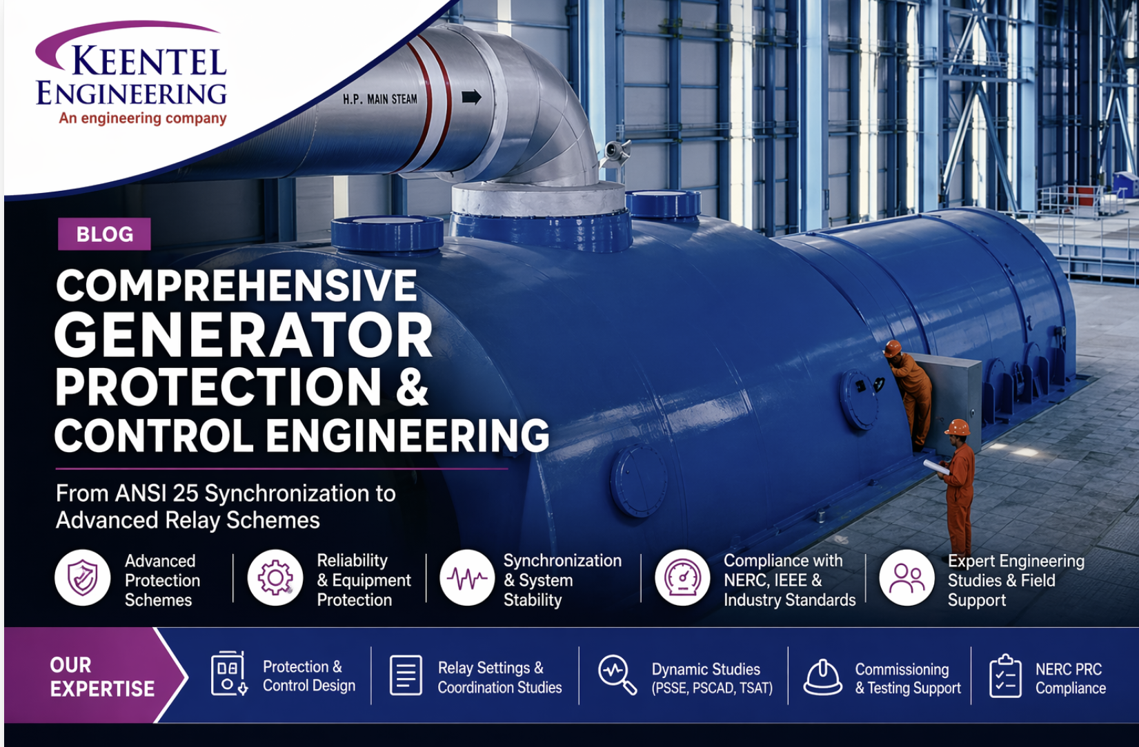
Comprehensive Generator Protection & Control Engineering From ANSI 25 Synchronization to Advanced Relay Schemes By Keentel Engineering Protection & Control Experts
Apr 24, 2022 | blog
1. Introduction: Why Generator Protection Is Critical
Generator systems represent some of the most capital-intensive and mission-critical assets in the power system. A single protection failure can result in:
- Catastrophic mechanical damage
- Extended outages and revenue loss
- Safety hazards for personnel
- Grid instability
One of the most dangerous yet underestimated events is improper synchronization, where even minor phase mismatch can produce severe electromechanical stress.
For example, an angular mismatch as small as 12° can generate 150% torque on the generator shaft, leading to violent mechanical oscillations and long-term fatigue .
At Keentel Engineering, we design robust, standards-compliant generator protection schemes that integrate protection, control, and system dynamics to ensure reliability and compliance.
2. Fundamentals of Generator Operation
A synchronous generator operates based on electromagnetic induction:
- A rotating magnetic field (exciter) induces voltage in stator windings
- Three-phase systems produce:
- Equal magnitude voltages
- 120° phase displacement between phases
This fundamental behavior defines:
- Protection requirements
- Synchronization constraints
- Stability limits
3. Generator System Architecture
A modern generator system includes:
- Synchronization Unit (ANSI 25)
- Automatic Voltage Regulator (AVR)
- Governor (speed control)
- Protective Relay System
These systems must operate in coordination. Protection cannot be designed in isolation it must consider:
- Dynamic system response
- Mechanical limitations
- Grid interaction
4. Synchronization & ANSI 25 Protection
4.1 The Risk of Improper Synchronization
Out-of-phase synchronization can cause:
- Severe shaft torque
- Rotor/stator stress
- Transformer and winding damage
Even small mismatches can escalate quickly:
- 12° mismatch → 1.5 pu torque
4.2 ANSI 25 – Synchronizing Check Function
The ANSI 25 relay ensures safe breaker closure by verifying:
- Voltage magnitude match
- Frequency match (slip)
- Phase angle alignment
Typical Engineering Settings:
- Phase angle window: ±5°
- Slip frequency: ~0.05 Hz
- Voltage mismatch: < 5%
4.3 Best Practices
- Use independent sync-check relay (not embedded in auto synchronizer)
- Maintain generator slightly:
- Higher frequency
- Slightly higher voltage
- Prevent reverse power (motoring)
4.4 Advanced Features
Modern relays include:
- Slow breaker detection
- Integration with breaker failure protection
5. Generator Grounding Design (Critical Engineering Decision)
Grounding determines:
- Fault current magnitude
- Equipment damage level
- Protection sensitivity
Key Requirement:
- Fault current should be limited to ≤ 10 A to avoid stator core damage
5.1 Grounding Methods Comparison
| Method | First Name | Key Use |
|---|---|---|
| High Resistance | 3–25 A | Most utility generators |
| Peterson Coil | ~1 A | Highly sensitive systems |
| Low Resistance | Up to 200 A | Large interconnected plants |
| Reactance Grounding | 25–100% of 3φ | Special applications |
| Solid Grounding | Very high | Requires fast protection |
| Ungrounded | ~0 A | Marine / niche |
6. Primary Generator Protection Schemes
6.1 Stator Differential Protection (87G)
- Detects internal faults
- Uses dual-slope characteristic
- Immune to CT errors with proper design
6.2 100% Stator Ground Fault Protection
Combination of:
- Neutral overvoltage → ~95% coverage
- Third harmonic undervoltage → remaining 5%
6.3 Negative Sequence Protection (46)
- Protects against rotor heating
- Based on thermal limit (K factor)
6.4 Reverse Power Protection (32)
- Detects loss of prime mover
- Prevents turbine damage due to motoring
6.5 Low Forward Power Protection
- Prevents overspeed conditions
- Used for controlled shutdown logic
6.6 Inadvertent Energization Protection
- Prevents generator from acting as motor
- Protects against:
- High inrush current
- Rapid overheating
7. AVR Backup Protection
Includes:
- Loss of excitation (ANSI 40)
- Overvoltage (ANSI 59)
- Overfluxing (V/Hz)
Risks:
- Rotor instability
- Core saturation
- Insulation damage
8. Governor Backup Protection
Includes:
- Underfrequency (81U)
- Over Frequency (81O)
System Insight:
- Frequency reflects balance between generation and load
9. Mechanical & Electrical Damage Mechanisms
Mechanical Risks:
- Shaft torsional stress
- Resonance and fatigue
- Turbine damage
Electrical Risks:
- High fault current
- Thermal stress
- Insulation breakdown
Out-of-phase events can produce extremely high currents:
- Generator current can exceed 100,000 A under severe conditions
10. Modern Digital Protection & Engineering Practices
Modern protection systems incorporate:
- Microprocessor relays (SEL, GE, Siemens)
- Advanced logic schemes
- Breaker failure coordination
- Dynamic modeling using:
- PSSE
- PSCAD
- TSAT
At Keentel Engineering we integrate:
- Protection design
- Dynamic studies
- Compliance (NERC PRC, IEEE)
- Commissioning support
11. Why Choose Keentel Engineering?
We provide:
- Complete generator protection design
- Relay settings & coordination studies
- NERC PRC compliance support
- Renewable interconnection expertise
- Substation P&C engineering
- Field commissioning & testing
Advanced Technical FAQs (25)
1. What is the purpose of ANSI 25?
To ensure safe synchronization by verifying voltage, frequency, and phase angle before breaker closure.
2. What is the acceptable phase angle difference for synchronization?
Typically within ±5°, with absolute limits around 10°.
3. What happens if a generator is synchronized out of phase?
It can experience severe torque shock (up to 150%), damaging mechanical components.
4. Why is slip frequency important?
It determines how fast the phase angle changes and impacts breaker closing accuracy.
5. What is the ideal voltage condition during synchronization?
Generator voltage should be slightly higher than system voltage to ensure reactive power export.
6. Why must sync-check relays be independent?
To avoid common-mode failures with automatic synchronizers.
7. What is stator differential protection?
A scheme that compares incoming and outgoing current to detect internal faults.
8. Why is 100% stator ground fault protection needed?
Because traditional protection only covers ~95% of winding.
9. What is third harmonic protection?
It detects faults near the neutral by monitoring harmonic voltage collapse.
10. What is negative sequence current?
Unbalanced current that causes rotor heating.
11. What is the generator K-factor?
A thermal limit constant defining allowable negative sequence current.
12. What causes reverse power?
Loss of prime mover, causing generator to draw power from the grid.
13. What is generator motoring?
When a generator operates as a motor due to reverse power flow.
14. Why is grounding important?
It limits fault current and reduces equipment damage.
15. What is high resistance grounding?
A method that limits fault current to low levels (3–25 A).
16. What is a Peterson coil?
A grounding method using reactance to limit fault current to ~1 A.
17. What is overfluxing?
Excessive V/Hz ratio causing core saturation and overheating.
18. What causes loss of excitation?
Failure of AVR or field system.
19. What is inadvertent energization?
Energizing a generator when not synchronized or at standstill.
20. Why is breaker failure protection needed?
To clear faults when the primary breaker fails.
21. What is slow breaker protection?
Detects delayed breaker closing during synchronization.
22. What is underfrequency protection?
Trips generator when system frequency drops below safe limits.
23. What is overfrequency protection?
Protects against excessive speed due to load loss.
24. What is CT selection criteria for generators?
CTs must avoid saturation and operate below knee-point limits during faults.
25. How does Keentel Engineering support generator protection?
Through design, studies, relay settings, compliance, and commissioning services.
Case Studies Generator Protection & Control (Keentel Engineering)
Case Study 1: Preventing Catastrophic Out-of-Phase Synchronization (ANSI 25 Implementation)
Project Type:
Utility-scale natural gas power plant (500 MW class)
Challenge:
The client experienced multiple near-miss synchronization events due to:
- Inconsistent operator practices
- Aging synchronization system
- No independent sync-check supervision
A post-event analysis showed:
- Phase angle mismatches approaching 10–12°, posing severe risk of shaft damage
Keentel Engineering Solution:
We performed a full synchronization protection audit and redesign, including:
1. Protection System Upgrade
- Implemented independent ANSI 25 sync-check relay
- Separated logic from auto-synchronizer to eliminate common failure modes
2. Relay Setting Optimization
- Phase angle window: ±5°
- Slip frequency limit: ≤ 0.05 Hz
- Voltage mismatch: < 5%
3. Breaker Timing Integration
- Modeled breaker closing time (~0.2 sec)
- Calculated worst-case synchronization angle
- Verified compliance with <10° mechanical limit
4. Slow Breaker Protection
- Enabled logic to detect delayed breaker closure
- Integrated with breaker failure scheme
Results:
- Eliminated unsafe synchronization events
- Reduced mechanical stress risk by >90%
- Improved operator confidence and system reliability
Key Value Delivered:
Keentel transformed synchronization from an operator-dependent process into a fully engineered protection-controlled system.
Case Study 2: 100% Stator Ground Fault Protection Upgrade
Project Type:
Hydroelectric generating station (multiple units)
Challenge:
Existing protection only provided:
- ~95% stator winding coverage
The remaining 5% near neutral was unprotected, creating risk of:
- Undetected insulation failure
- Progressive stator core damage
Keentel Engineering Solution:
1. Dual Protection Implementation
- Installed:
- Neutral overvoltage (59N) → 95% coverage
- 3rd harmonic undervoltage (27TH) → remaining 5%
2. Sensitivity Optimization
- Calibrated third harmonic thresholds based on:
- Machine characteristics
- Operating conditions
3. Two-Stage Protection Logic
- Stage 1: Alarm
- Stage 2: Trip (with time delay)
4. System Coordination
- Coordinated with:
- Grounding scheme
- Existing protection devices
Results:
- Achieved 100% stator ground fault coverage
- Early detection of insulation degradation
- Reduced risk of catastrophic stator failure
Key Value Delivered:
Enhanced protection coverage enabled predictive maintenance and avoided multi-million-dollar stator repair risks.
Case Study 3: Generator Grounding Redesign for Damage Mitigation
Project Type:
Industrial cogeneration plant (combined heat & power)
Challenge:
The generator was originally:
- Solidly grounded
- Producing high ground fault currents
This resulted in:
- Elevated risk of stator core damage
- Increased fault energy during ground faults
Keentel Engineering Solution:
1. Grounding Study & Modeling
- Performed fault current analysis
- Evaluated multiple grounding strategies
2. High Resistance Grounding Implementation
- Installed grounding transformer + resistor
- Limited fault current to <10 A
3. Protection Coordination
- Updated:
- Neutral overvoltage protection
- Ground fault detection schemes
4. Equipment Verification
- Verified CT/VT performance under new conditions
Results:
- Reduced ground fault current by >95%
- Eliminated stator core damage risk
- Improved system safety and maintainability
Key Value Delivered:
Keentel enabled a low-damage fault environment, significantly extending generator life.
Case Study 4: Negative Sequence Protection for Rotor Thermal Protection
Renewable energy plant (wind + synchronous condenser support)
Challenge:
Frequent system imbalance caused:
- Elevated negative sequence currents
- Rotor overheating concerns
The existing protection:
- Was not aligned with manufacturer K-factor limits
Keentel Engineering Solution:
1. Thermal Capability Analysis
- Reviewed generator manufacturer data
- Calculated K-factor limits
2. Relay Setting Development
- Configured:
- Inverse-time negative sequence protection
- Definite-time alarm thresholds
3. Thermal Modeling
- Implemented thermal memory function
- Accounted for cumulative heating effects
4. System Diagnostics
- Identified contributing causes:
- Unbalanced loads
- Potential CT wiring inconsistencies
Results:
- Prevented rotor overheating events
- Improved generator operational limits
- Reduced forced outages
Key Value Delivered:
Keentel ensured thermal protection aligned with actual machine capability, not generic settings.
Case Study 5: Inadvertent Energization Protection & Commissioning Correction
Project Type:
New utility-scale generator interconnection (ERCOT region)
Challenge:
During commissioning, the system had risk of:
- Breaker closing while generator at standstill
- Potential for generator acting as an induction motor
This could result in:
- Extremely high current
- Severe rotor/stator damage
Keentel Engineering Solution:
1. Protection Scheme Implementation
- Configured inadvertent energization protection (ANSI 50/27 logic)
2. Arming Logic Design
- Enabled protection when:
- Generator offline
- Voltage below threshold
3. Fast Trip Logic
- Immediate trip on:
- Unexpected current flow
- Unsafe energization condition
4. Commissioning Validation
- Simulated energization scenarios
- Verified trip response time
Results:
- Eliminated energization risk during startup
- Ensured safe commissioning process
- Passed utility interconnection requirements
Key Value Delivered:
Keentel prevented a high-risk commissioning failure scenario, protecting both equipment and project timeline.

About the Author:
Sandip "Sonny" R. Patel, P.E.
IEEE Senior Member · Founder & CEO, Keentel Engineering
In 1995, Sonny Patel earned his Electrical Engineering degree from the University of Illinois. But degrees don't build legacies — action does.
For three decades, he has worked the power industry from every side of the table: 16 years as a utility engineer at Exelon/Commonwealth Edison; generation leadership across hydroelectric, industrial steam turbine, and a 9 GW renewable fleet; NERC Regional Entity Senior Compliance Engineer and Audit Team Lead, auditing some of the nation's largest utilities; and testing and commissioning lead on equipment up to 765 kV — the very top of the North American grid.Utility. Generator. Regulator. Consultant. Few engineers have seen all four seats. Fewer still have sat in them.
His experience spans nuclear, hydro, conventional generation, renewables, oil and gas, mining — and today's data centers, where he is authoring a three-book series on data center design. He is a Licensed Professional Engineer in six states and a Licensed Electrical Contractor in Florida (Unlimited EC) — he doesn't just design the work; he's qualified to stand behind its execution.Today, as Founder and CEO of Keentel Engineering, Sonny leads a nationwide team of engineers delivering substation design, power system studies, NERC compliance, and commissioning — done right, coast to coast.Three decades. Every side of the table. One standard: accountable engineering.
Services

Let's Discuss Your Project
Let's book a call to discuss your electrical engineering project that we can help you with.
About the Author:
Sandip "Sonny" R. Patel, P.E.
IEEE Senior Member · Founder & CEO, Keentel Engineering
In 1995, Sonny Patel earned his Electrical Engineering degree from the University of Illinois. But degrees don't build legacies — action does.
For three decades, he has worked the power industry from every side of the table: 16 years as a utility engineer at Exelon/Commonwealth Edison; generation leadership across hydroelectric, industrial steam turbine, and a 9 GW renewable fleet; NERC Regional Entity Senior Compliance Engineer and Audit Team Lead, auditing some of the nation's largest utilities; and testing and commissioning lead on equipment up to 765 kV — the very top of the North American grid.
Utility. Generator. Regulator. Consultant. Few engineers have seen all four seats. Fewer still have sat in them.
His experience spans nuclear, hydro, conventional generation, renewables, oil and gas, mining — and today's data centers, where he is authoring a three-book series on data center design. He is a Licensed Professional Engineer in six states and a Licensed Electrical Contractor in Florida (Unlimited EC) — he doesn't just design the work; he's qualified to stand behind its execution.
Today, as Founder and CEO of Keentel Engineering, Sonny leads a nationwide team of engineers delivering substation design, power system studies, NERC compliance, and commissioning — done right, coast to coast.Three decades. Every side of the table. One standard: accountable engineering.
Leave a Comment
Thank you for contacting us.
We will get back to you as soon as possible.
We will get back to you as soon as possible.
Oops, there was an error sending your message.
Please try again later.
Please try again later.
Related Posts

By SANDIP R PATEL
•
October 3, 2026
October 03, 2026 | Blog

By SANDIP R PATEL
•
September 30, 2026
Learn NERC and ERCOT compliance requirements for natural gas power plants, including GO/GOP obligations, O&P standards, GADS reporting, and audits.

By SANDIP R PATEL
•
September 26, 2026
Learn how to prepare a MISO large-load interconnection package, including PSS®E models, BESS smoothing, harmonic data and transmission-owner requirements.

By SANDIP R PATEL
•
September 26, 2026
Learn where storage belongs in an 800 VDC AI data center, including capacitors, flywheels, BESS, fault current, protection, grounding, and EMT design.

By SANDIP R PATEL
•
September 26, 2026
Learn how SPP’s HILL and HILLGA framework works for large-load projects, including studies, BTM generation, modeling, EMT requirements, and firm service.

By SANDIP R PATEL
•
September 25, 2026
Learn how IBR time synchronization, IEEE 2800, IRIG-B verification, and PTP solutions help meet disturbance monitoring compliance requirements.

By SANDIP R PATEL
•
September 24, 2026
Learn why continuing technical training matters in power engineering, including standards, software skills, PDH requirements, and career growth.
By SANDIP R PATEL
•
September 22, 2026
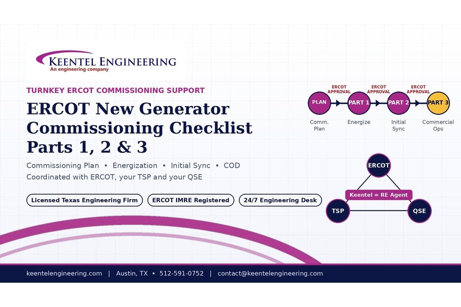
2026 ERCOT commissioning guide covering the Commissioning Plan, Checklist Parts 1–3, BESS requirements, TSP/QSE coordination, field testing and COD.

By SANDIP R PATEL
•
September 22, 2026
Learn PRC-030-1 R1 event detection requirements for inverter-based resources, SEL platforms, disturbance monitoring, and audit-ready compliance.





