
A Coordinated Electric System Interconnection Review—the utility’s deep-dive on technical and cost impacts of your project.
Challenge: Frequent false tripping using conventional electromechanical relays
Solution: SEL-487E integration with multi-terminal differential protection and dynamic inrush restraint
Result: 90% reduction in false trips, saving over $250,000 in downtime
The three operating regions you have to design to
| Device | Output vs voltage | Response | Best suited to | Main limitations |
|---|---|---|---|---|
| Mechanically switched capacitor or reactor | Proportional to voltage squared | Seconds; discrete steps; limited switching operations per day | Steady-state reactive supply, voltage profile, loss reduction | No dynamic capability; step voltage change on switching; capability collapses when most needed |
| Static var compensator | Capacitive branches proportional to voltage squared | A few cycles; continuously controllable | Continuous control where cost matters and deep voltage support is not the driver | Square-law capability loss; harmonic filters are part of the plant and interact with the network |
| STATCOM | Approximately proportional to voltage — constant current capability | One to two cycles closed loop; converter response faster still | Voltage stability margin, weak interconnections, fast disturbance recovery, flicker and unbalance compensation | Higher capital cost; converter losses; adds a converter and its control dynamics to the network |
| Synchronous condenser | Governed by machine capability and excitation | Excitation response in the hundreds of milliseconds; inherent inertial response instantaneous | System strength and inertia, short-circuit contribution, black start support | Rotating plant with maintenance and losses; slower controlled response than a converter |
| STATCOM with energy storage | Reactive as a STATCOM, plus real power within the storage rating | As STATCOM for reactive; real power limited by storage | Where a real power deficiency is part of the problem | Cost and complexity of the storage; different failure and maintenance profile |
| Stage | Keentel scope | Outcome |
|---|---|---|
| Screening | Series-compensation proximity, radial contingency review, UIF and short-circuit ratio screening, frequency scans | Early identification of which SSO types apply |
| Detailed studies | PSCAD/EMTDC EMT studies with vendor real-code models, impedance-based and frequency-scan analysis | Clear evidence of stability margins or risk |
| Model quality | EMT model review, benchmarking against positive-sequence models, model acceptance support | Models that system operators accept |
| Mitigation | Control retuning recommendations with vendors, SSDC and bypass logic requirements, protection and monitoring specifications | Practical, coordinated solutions |
| Interconnection support | SSR and SSO study reports for ISO and utility requirements, response to reviewer comments | Fewer delays in the interconnection process |
Resilience: designing CDUs to the facility Tier objective
Liquid cooling makes heat removal more critical, not less. Cold plates hold only seconds of thermal buffer. If TCS flow stops, processors throttle or shut down very quickly. Resilience design must therefore cover:
- Pump redundancy: N+1 pumps at minimum, with automatic changeover.
- CDU redundancy: N+1 CDUs on a common TCS header, or 2N CDUs serving A and B manifolds for fault-tolerant designs.
- Power to CDUs: dual-corded CDUs fed from A and B sources, with pumps and controls on UPS power so coolant keeps flowing through a utility failure and generator start. This is the liquid-cooling equivalent of continuous cooling.
- Facility water continuity: chilled water or condenser water must also continue, through thermal storage, UPS-backed pumps or a high enough FWS temperature that the TCS can coast on stored thermal mass for the transfer period.
- Concurrent maintainability: isolation valves so any CDU, pump, filter or manifold section can be serviced without stopping the others.
- Leak management: leak detection, drip trays, automatic isolation valves and procedures for fluid spills.
Electrical engineering considerations
CDUs and liquid-cooling plants are electrical loads with their own design requirements:
- Pump motors and VFDs. Large CDUs use variable-frequency drives on their pump motors. These introduce harmonic current that must be included in the facility's harmonic study and IEEE 519 evaluation.
- Critical mechanical load on UPS. Putting CDU pumps on UPS increases UPS and battery sizing. The mechanical UPS load must be included in redundancy and ride-through calculations.
- Feeder and protection design. Dual feeds, automatic transfer, selective coordination and arc-flash labelling apply to CDU power distribution just as they do to IT power.
- Generator transient response. CDU pumps restarting together after a transfer create motor inrush on the generators. Staged restarts and soft acceleration reduce the step load.
- Load dynamics. AI training loads can swing rapidly between high and low power. Cooling controls must track those swings without temperature overshoot, and electrical systems must handle both the IT and the cooling load changes.
Commissioning a liquid-cooled data hall
- Flush and clean the TCS piping and manifolds to the specified cleanliness, using high-purity flush water.
- Fill and vent with the specified coolant, verifying glycol concentration and chemistry.
- Pressure test for leaks at design and test pressures, including quick-disconnect fittings.
- Verify sensors and controls: flow meters, temperature sensors, pressure transmitters, leak detection and BMS points.
- Load test with heat load banks connected through the cold-plate interfaces or rack manifolds, across the operating range.
- Prove the heat balance on both loops at several load steps, and the approach temperature against the design.
- Test failure scenarios: pump failure, CDU failure, power transfer to generator, valve failure and loss of facility water, confirming temperatures stay within the IT vendor's limits.
How Keentel Engineering helps
Keentel Engineering supports data center owners, developers and EPCs with the electrical engineering that liquid-cooled facilities depend on, and coordinates with the mechanical engineer of record and cooling vendors on the integrated design.
Insulator Swing Angle and Its Impact on Transmission Line ROW: A US Engineering Guide
October 09, 2026 | Blog
Part A — Insulator Swing and Right-of-Way at a Glance
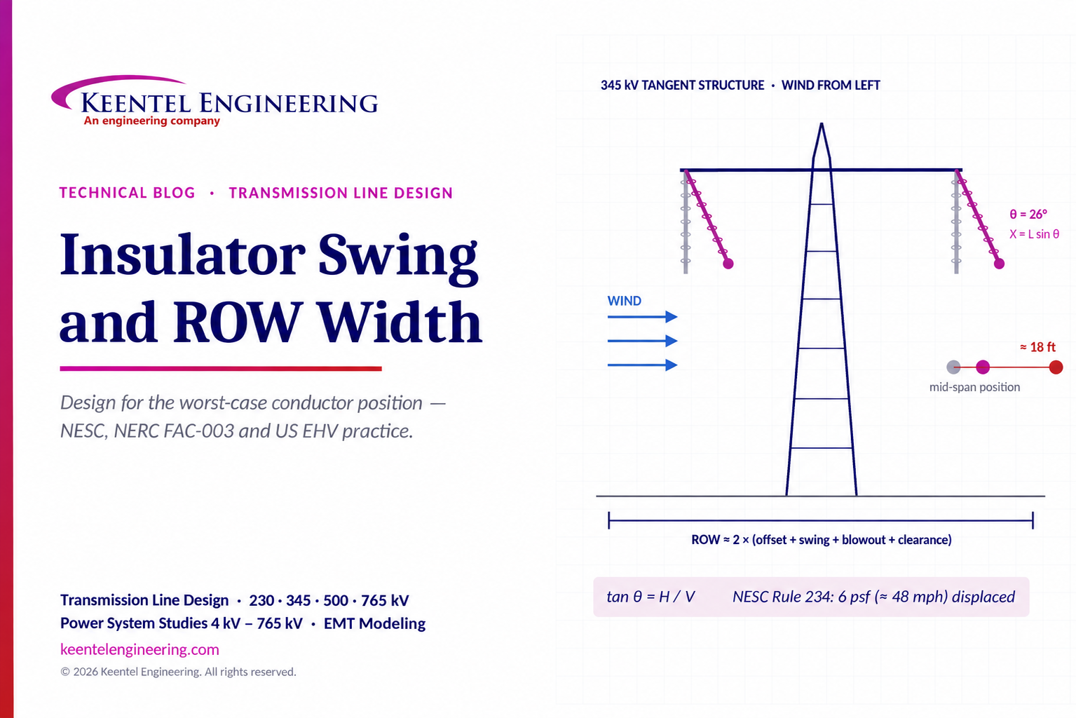
When wind blows across an overhead transmission line, suspension insulator strings swing away from vertical and conductors blow out sideways. The conductor does not stay where the plan-and-profile drawing shows it at rest. Right-of-way (ROW) width, structure geometry and clearances must therefore be designed for the worst credible conductor position, not the no-wind position.
How wind moves the conductor
| Effect | What happens | Where it matters most |
|---|---|---|
| Insulator swing | The suspension string rotates about its attachment point, moving the conductor clamp sideways | At the structure: clearance from conductor to tower steel, crossarm and guy wires |
| Conductor blowout | The sagged conductor rotates sideways about the line between its attachment points | At mid-span: clearance to buildings, vegetation, other circuits and the ROW edge |
| Combined envelope | Swing plus blowout, at the governing wind and temperature | Required horizontal clearances and ROW width |
The core relationships
- Swing angle: the ratio of transverse load to vertical load at the insulator, tan θ = H ÷ V.
- Lateral swing displacement: X = L × sin θ, where L is the insulator assembly length.
- Conductor blowout at mid-span: approximately D × sin φ, where D is the sag and φ is the conductor's wind-deflection angle.
- ROW half-width: distance from centerline to outer phase, plus swing displacement, plus blowout, plus the required clearance.
Why it matters in US practice
- NESC (ANSI C2): horizontal clearances to buildings and other installations are checked with the conductor at rest and displaced by a 6 psf wind, about 48 mph.
- NERC FAC-003: for lines operated at 200 kV and above, vegetation must stay outside the Minimum Vegetation Clearance Distance while the conductor sags and sways.
- Structure design: swing sets the phase-to-structure clearances for power-frequency, switching-surge and lightning conditions.
- Cost: every foot of extra ROW width adds acquisition, clearing and maintenance cost over the life of the line.
Design for the worst-case conductor position, not the no-wind position.
Part B — Insulator Swing Angle and Its Impact on Transmission Line ROW: A US Engineering Guide
How suspension insulator swing and conductor blowout drive structure clearances and right-of-way width on 115 kV to 765 kV US transmission lines, with NESC and NERC criteria and a fully worked 345 kV example.
Why the conductor's at-rest position is not enough
A plan-and-profile drawing shows each conductor hanging in a vertical plane beneath its insulators. In reality, wind pushes on the conductors and insulators, the suspension strings swing, and the conductor between structures blows out sideways. At high wind, the outer phase of a 345 kV line can move 20 feet or more toward the edge of the right-of-way at mid-span.
Three engineering questions follow:
- At the structure: does the swung conductor keep enough clearance from the tower body, crossarm, guys and other phases?
- Along the span: does the blown-out conductor keep the required clearance from buildings, signs, vegetation, roads, railroads and other circuits?
- For the corridor: how wide must the ROW be so those clearances are always met within it?
All three depend on how far the conductor moves, which depends on swing angle and blowout.
US voltage classes and typical ROW widths
US high-voltage and extra-high-voltage transmission uses standard nominal voltages from ANSI C84.1 and utility practice:
| Nominal voltage | Typical use | Indicative ROW width for a single circuit |
|---|---|---|
| 115 kV / 138 kV | Sub-transmission and regional transmission | 75–100 ft |
| 161 kV | Regional transmission (some systems) | 80–100 ft |
| 230 kV | Bulk transmission | 100–125 ft |
| 345 kV | EHV bulk transmission | 125–150 ft |
| 500 kV | EHV bulk transmission | 150–200 ft |
| 765 kV | UHV/EHV backbone transmission | About 200 ft or more |
Widths vary widely with structure type, span length, conductor, terrain, local codes and utility standards. They are a starting point, not a substitute for a calculated ROW.
The insulator swing angle
Forces on a suspension insulator
A suspension insulator at a tangent or small-angle structure carries:
- Vertical load: the weight of conductor over the structure's weight span, plus half the insulator assembly weight, plus any ice.
- Transverse load: wind on the conductor over the structure's wind span, plus wind on the insulator, plus, at angle structures, the horizontal component of conductor tension caused by the line angle.
The string hangs along the resultant of these loads, so:

In the form used in US transmission design practice:

| Symbol | Meaning | Units |
|---|---|---|
| p | Wind pressure on the conductor | psf |
| d | Conductor diameter | ft |
| n | Number of subconductors per phase | — |
| S_wind | Wind span (horizontal span) | ft |
| T | Conductor tension per subconductor at the swing condition | lb |
| α | Line angle at the structure | degrees |
| W_ins,wind | Wind load on the insulator assembly | lb |
| w | Conductor unit weight, including ice if applicable | lb/ft |
| S_weight | Weight span (vertical span) | ft |
| W_ins | Insulator assembly weight | lb |
The simple form tan θ = F_t ÷ W is correct, but the details matter:
- Wind span and weight span are different. Wind span is half the sum of the adjacent spans. Weight span is the horizontal distance between the low points of the adjacent spans, and it changes with terrain and temperature.
- Line angle adds a large transverse force. Even a few degrees of line angle can add more transverse load than the wind itself.
- Insulator weight helps. Heavier assemblies swing less; lighter polymer insulators swing more for the same wind.
Lateral displacement at the structure:
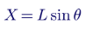
where L is the length of the insulator assembly from the attachment point to the conductor clamp. The conductor also rises by L(1 − cos θ), which slightly increases ground clearance at the structure.
Conductor blowout
Between structures, the sagged conductor rotates sideways about the chord joining its attachment points. Its blowout angle follows the ratio of wind load to weight per unit length:
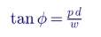
At mid-span, the horizontal displacement of the conductor from its at-rest position is approximately:

where D is the sag at the wind condition being checked. Line design software such as PLS-CADD calculates the full three-dimensional position, including the change in sag that wind loading causes, but the simple form shows why long, high-sag spans need wide ROWs.
Which wind and which clearance?
Different clearances are checked at different wind conditions, because the events that cause flashover happen at different times:
| Clearance check | Typical wind condition | Governing criteria |
|---|---|---|
| Horizontal clearance to buildings, signs and other installations | At rest, and displaced by 6 psf wind (about 48 mph) at the specified conductor temperature | NESC Rule 234 |
| Phase-to-structure clearance, power frequency | High wind, as defined in utility criteria | Utility standards, insulation coordination |
| Phase-to-structure clearance, switching surge | Moderate wind, as defined in utility criteria | Insulation coordination studies |
| Phase-to-structure clearance, lightning | No or low wind | Lightning performance studies |
| Vegetation clearance | Conductor positions under rated electrical and loading conditions, including sag and sway | NERC FAC-003 and utility vegetation programmes |
| Structure strength | Extreme wind and combined ice and wind | NESC Rule 250 loading districts and extreme wind provisions |
The NESC 6 psf wind pressure corresponds to about 48 mph, from p = 0.00256 V² with V in mph.
Utilities set their own allowable swing angles for each clearance condition, based on structure geometry, voltage and insulation coordination. A swing limit of 30–45° is common for power-frequency clearance on many structure families, but the governing value comes from the clearance geometry of the specific structure and the utility's design criteria, not a universal rule.
Vegetation: NERC FAC-003
For lines operated at 200 kV and above, and certain lower-voltage critical lines, NERC FAC-003 requires vegetation to be kept outside the Minimum Vegetation Clearance Distance (MVCD), derived from the Gallet equation, while the conductor sags and sways. At sea level to 500 ft elevation, the FAC-003-5 alternating-current values include:
| Nominal voltage | MVCD (ft) |
|---|---|
| 230 kV | 4.0 |
| 345 kV | 4.3 |
| 500 kV | 7.0 |
| 765 kV | 11.6 |
Mitigation should be validated in the same EMT study set that identified the problem, across all relevant operating conditions and outages.
Monitoring: seeing PEDI in the field
Many PEDI oscillations are in the 5–50 Hz range. Synchrophasor measurements at standard reporting rates of 30 or 60 frames per second can alias or filter oscillations at the higher end of that range. Point-on-wave recording at kilohertz sample rates, high-speed digital fault recorders and plant-level data recorders are needed to capture and diagnose them. Requiring high-resolution monitoring at IBR plants, and keeping the data long enough to analyse events, makes post-event investigation far more effective.
How Keentel Engineering helps
Keentel Engineering delivers
power system studies from 4 kV to 765 kV, with EMT modelling for IBR, BESS, HVDC and FACTS interconnections.
| Parameter | TCS (PG25) | FWS (water) |
|---|---|---|
| Heat load | 1,000 kW | 1,000 kW plus pump heat |
| Supply temperature | 30 °C | 25 °C (approach 5 K; ASHRAE W27) |
| Return temperature | ≈ 40 °C | ≈ 33 °C |
| Temperature rise | ≈ 10 K | 8 K |
| Flow | 1,500 L/min (1.5 L/min per kW) | ≈ 1,800 L/min |
Step 1 — Swing angle at 6 psf.
Transverse load: 6 × (1.196 ÷ 12) × 2 × 1,100 ≈ 1,316 lb.
Vertical load: 1.229 × 2 × 1,000 + 400 ÷ 2 ≈ 2,658 lb.
tan θ = 1,316 ÷ 2,658 ≈ 0.495, so θ ≈ 26.3°.
Step 2 — Lateral swing displacement. X = 11 × sin 26.3° ≈ 4.9 ft.
Step 3 — Conductor blowout. tan φ = (6 × 0.0997) ÷ 1.229 ≈ 0.49, so φ ≈ 25.9°. Mid-span displacement ≈ 30 × sin 25.9° ≈ 13.1 ft.
Step 4 — Total conductor movement at mid-span. 4.9 + 13.1 ≈ 18.0 ft toward the ROW edge.
Step 5 — ROW half-width. Outer phase offset (25 ft) + movement (18 ft) + required horizontal clearance and utility margin (assume 15 ft, based on the NESC Rule 234 value for the line's voltage plus utility buffer) ≈ 58 ft. Full ROW ≈ 116 ft, rounded to about 120–125 ft.
This sits at the lower end of the typical 345 kV range. Longer spans, higher sag, buildings at the ROW edge or vegetation programme buffers push it wider.
How sensitive is the answer?
| Change from the base case | Swing angle | Effect |
|---|---|---|
| Base case: 6 psf, porcelain I-string, tangent | 26.3° | Reference |
| Higher wind for the clearance check (9 psf) | 36.6° | Swing displacement 6.6 ft; blowout 17.7 ft; total movement about 24 ft |
| Lighter polymer insulator (about 100 lb) | 27.7° | Slightly more swing for the same wind |
| Short weight span (300 ft, structure low in a valley) | 54.5° | Severe swing; phase-to-structure clearance likely violated |
| 5° line angle with about 8,000 lb tension per subconductor | 45.6° | Line angle dominates; angle structures need different hardware |
The short weight span case is the one that catches designers out. A structure at the bottom of a valley, or one with an uplift tendency at low temperature, carries little conductor weight, so even a moderate wind swings its insulators far toward the tower.
Reducing swing and ROW width
| Change from the base case | Swing angle | Effect |
|---|---|---|
| Base case: 6 psf, porcelain I-string, tangent | 26.3° | Reference |
| Higher wind for the clearance check (9 psf) | 36.6° | Swing displacement 6.6 ft; blowout 17.7 ft; total movement about 24 ft |
| Lighter polymer insulator (about 100 lb) | 27.7° | Slightly more swing for the same wind |
| Short weight span (300 ft, structure low in a valley) | 54.5° | Severe swing; phase-to-structure clearance likely violated |
| 5° line angle with about 8,000 lb tension per subconductor | 45.6° | Line angle dominates; angle structures need different hardware |
The short weight span case is the one that catches designers out. A structure at the bottom of a valley, or one with an uplift tendency at low temperature, carries little conductor weight, so even a moderate wind swings its insulators far toward the tower.
Reducing swing and ROW width
| Measure | How it helps | Trade-offs |
|---|---|---|
| V-string insulators | Restrain the conductor; essentially no swing at the structure | More insulators and hardware; higher structure loads |
| Braced post or horizontal post insulators | Fix the conductor position on compact lines | Limited to lower voltages and shorter spans; strength limits |
| Insulator weights | Increase vertical load and reduce swing | Extra hardware and structure load |
| Shorter spans | Reduce sag and blowout | More structures |
| Higher design tension | Reduces sag and blowout | Higher structure loads; vibration control needed |
| Vertical or delta phase configuration | Reduces the outer phase offset from centerline | Taller structures; different electrical and EMF characteristics |
| Careful tower spotting | Avoids short weight spans and uplift | Requires accurate terrain and design modelling |
Compact line designs in constrained US corridors often combine V-strings or braced posts with shorter spans and vertical configurations to fit 230 kV or 345 kV lines within narrower ROW.
A complete ROW width check
A defensible ROW width combines several independent checks. The governing one sets the width:
- Conductor envelope and NESC clearances: at-rest and 6 psf displaced positions, with NESC Rule 234 horizontal clearances to buildings and other installations at the ROW edge.
- Utility clearance criteria: any utility-specific wind conditions and buffers beyond the NESC minimums.
- Vegetation management: the swung conductor envelope plus FAC-003 MVCD, growth allowance and danger-tree considerations.
- Electric and magnetic fields and audible noise: state or utility limits at the ROW edge, more significant at 345 kV and above.
- Induced voltages and parallel facilities: clearances to pipelines, fences, other lines and railroads.
- Construction and maintenance access: room for equipment, stringing and future work.
- Future upgrades: reconductoring or uprating that may increase sag.
How Keentel Engineering helps
Keentel Engineering delivers transmission line design and power system studies from 4 kV to 765 kV.
| Stage | Keentel scope | Outcome |
|---|---|---|
| Routing and corridor studies | ROW width calculations for alternative structure types and routes | Defensible corridor widths before land acquisition |
| Line design | PLS-CADD modelling, sag-tension, insulator swing checks, tower spotting and clearance analysis | Structures and spans that meet clearances in every condition |
| Insulation coordination | Phase-to-structure clearances for power-frequency, switching-surge and lightning conditions | Reliable insulation performance |
| Code compliance | NESC clearance and loading checks; NERC FAC-003 conductor envelope data for vegetation programmes | Compliant designs and clear vegetation criteria |
| Rebuilds and uprates | Swing and clearance reviews for reconductoring, insulator replacement and voltage upgrades | Upgrades that fit within existing ROW |
Planning a new line, a rebuild or an uprate in a constrained corridor? Talk to Keentel Engineering at (813) 389-7871, contact@keentelengineering.com, or book a 15-minute scoping call at calendly.com/keentel-engineering/15min.
Part C — Case Studies
The following are illustrative scenarios based on conditions typical of US transmission projects. They show how Keentel Engineering approaches swing and ROW problems; site details are generalised and figures are rounded.
Case Study 1 — 230 kV rebuild: polymer insulators and a building at the ROW edge
Situation. A utility rebuilds an aging 230 kV wood-pole line on its existing 100 ft ROW, replacing porcelain strings with lighter polymer insulators. A commercial building has been built close to the ROW edge since the line was originally constructed.
Analysis. PLS-CADD modelling shows that the lighter insulators and new conductor increase swing at the structures nearest the building. With the conductor displaced by 6 psf wind, the outer phase comes within the NESC Rule 234 horizontal clearance from the building at two spans.
Engineered solution. Braced post insulators on the structures adjacent to the building to fix the conductor position, combined with one additional structure to shorten the critical span and reduce blowout.
Outcome. The rebuilt line meets NESC horizontal clearances at rest and displaced, within the existing ROW, with no new easement needed.
Case Study 2 — 345 kV new line in a constrained suburban corridor
Situation. A new 345 kV line must follow a suburban corridor where the available ROW is about 125 ft, narrower than the utility's 150 ft standard for its lattice tower design.
Analysis. A ROW study compares the standard horizontal lattice design with compact alternatives. The governing factor is the outer phase offset plus mid-span blowout on 1,200 ft spans. EMF at the ROW edge is also checked.
Engineered solution. A vertical double-circuit-ready steel pole design with V-string insulators, 900 ft spans and a slightly higher design tension. The vertical configuration reduces the outer phase offset, V-strings remove swing at the structure, and shorter spans reduce blowout.
Outcome. The design meets NESC clearances, utility swing criteria and ROW-edge EMF limits within 125 ft, avoiding additional land acquisition along the most constrained segment.
Case Study 3 — 500 kV line: high swing at a valley structure
Situation. During detailed design of a 500 kV line across rolling terrain, swing checks flag a suspension structure at the bottom of a valley. At the design wind, its insulator swing angle far exceeds the structure's allowable value for power-frequency clearance.
Analysis. The structure's weight span is very short, because the adjacent spans' low points fall on the far sides of the neighbouring hills. At the cold, high-tension condition, the structure is close to uplift. The swing angle calculation shows the conductor approaching the tower window.
Engineered solution. Re-spot the structure higher on the slope to restore a normal weight span, and use a V-string assembly at a second marginal location. Insulation coordination clearances are rechecked for power-frequency, switching-surge and lightning conditions.
Outcome. All structures meet swing and clearance criteria across the full range of temperatures and winds, without adding structures to the line.
Part D — Technical FAQ: Insulator Swing and ROW
It is the angle between a suspension insulator string and the vertical when transverse loads, such as wind and line-angle tension, act on the conductor and insulator. The string aligns with the resultant of the transverse and vertical loads.
tan θ = transverse load ÷ vertical load. Transverse load includes wind on the conductor over the wind span, the line-angle component of tension and wind on the insulator. Vertical load includes conductor weight over the weight span, plus half the insulator weight.
Wind span is half the sum of the two adjacent spans and sets the wind load on the structure. Weight span is the horizontal distance between the low points of the adjacent spans and sets the conductor weight carried. On hilly terrain they can differ greatly.
Little vertical load means the same wind produces a much larger swing angle. In the worked example, cutting the weight span from 1,000 ft to 300 ft raises the swing from about 26° to about 54°, enough to violate phase-to-structure clearance.
A lot. The horizontal component of conductor tension, 2T sin(α/2) per subconductor, can exceed the wind load even at small angles. In the example, a 5° angle raises swing from 26° to about 46°, which is why angle structures use different insulator arrangements.
It is the sideways movement of the sagged conductor between structures under wind. At mid-span, the horizontal displacement is approximately the sag multiplied by the sine of the conductor's wind-deflection angle.
On long spans, blowout usually is. In the 345 kV example at 6 psf, insulator swing moves the conductor about 4.9 ft at the structure, while blowout adds about 13.1 ft at mid-span.
NESC Rule 234 checks horizontal clearances with the conductor at rest and displaced by a 6 psf wind, about 48 mph, at the specified conductor temperature and sag condition.
No. Structural loads use the NESC Rule 250 loading districts, extreme wind and combined ice and wind provisions. The 6 psf wind is a clearance condition representing a reasonably likely wind, not a structural extreme.
It depends on the structure geometry and the clearance condition. Utilities define allowable swing angles for power-frequency, switching-surge and lightning clearances. Values of 30–45° are common for power-frequency clearance on many structures, but the governing value must come from the specific structure and criteria.
Because the overvoltages occur under different conditions. Power-frequency voltage is always present, so it is checked at high wind. Switching surges are checked at moderate wind, and lightning at no or low wind, reflecting the low probability of the overvoltage and the wind occurring together.
FAC-003 requires vegetation to stay outside the Minimum Vegetation Clearance Distance while the conductor sags and sways under rated conditions. The swung and blown-out conductor envelope therefore defines where the MVCD is measured from.
At sea level to 500 ft elevation, FAC-003-5 lists about 4.0 ft for 230 kV, 4.3 ft for 345 kV, 7.0 ft for 500 kV and 11.6 ft for 765 kV. Values increase with elevation. They are minimum flashover distances, not clearing widths.
By the governing combination of outer phase offset, insulator swing, conductor blowout and required clearances, checked against NESC clearances, utility criteria, vegetation management, EMF limits, induced voltage and access needs. The widest requirement governs.
Yes, slightly. Polymer assemblies weigh much less than porcelain or glass strings, reducing vertical load. The effect is usually small compared with the conductor weight, but it matters on short weight spans and in rebuilds near existing clearances.
A V-string restrains the conductor in two directions, so the clamp does not swing at the structure. It eliminates swing displacement and allows a more compact tower window, at the cost of more insulators and higher structure loads.
Yes. Higher tension reduces sag and therefore blowout. It must be balanced against higher structure loads and increased aeolian vibration risk, which may require dampers.
It is the starting point of the ROW calculation. Horizontal configurations place the outer phases far from centerline, while vertical or delta configurations bring them closer and can significantly reduce ROW width for the same voltage.
Programs such as PLS-CADD model each span and structure in three dimensions, calculate sag and tension under each weather case, check insulator swing against allowable limits and evaluate clearances to terrain, buildings, vegetation and other features.
Checking only the at-rest position or typical tangent structures. The critical cases are usually short weight spans, line angles, long spans near buildings, and rebuilds that change insulator weight or conductor sag without rechecking swing and blowout.
References and Further Reading
Links were current at publication (October 2026).
1. ANSI C2: National Electrical Safety Code (NESC). Institute of Electrical and Electronics Engineers.
2. RUS Bulletin 1724E-200: High Voltage Transmission Line Design Manual. USDA Rural Utilities Service.
3. NERC Reliability Standard FAC-003-5: Transmission Vegetation Management. North American Electric Reliability Corporation.
4. PLS-CADD Technical Note: Insulator Swing Checks in PLS-CADD. Power Line Systems.
5. ANSI C84.1: Electric Power Systems and Equipment — Voltage Ratings (60 Hz). ANSI/NEMA.
Disclaimer
This article is general technical information for educational purposes. It is not engineering advice for any specific project and does not create a professional relationship. Conductor data, spans, sags, swing angles, ROW widths and clearance values are illustrative; actual designs must follow the current NESC edition, applicable state and local codes, utility design criteria and project-specific engineering analysis, sealed by a licensed professional engineer where required. Verify the current edition of any standard before relying on it.
Case studies are illustrative scenarios based on typical project conditions, not records of specific client projects. Figures are rounded and indicative.
NESC, IEEE, NERC, PLS-CADD and other names are the property of their respective owners. Keentel Engineering is not affiliated with or endorsed by these organisations or any software or equipment vendor.
| Office | Address | Phone |
|---|---|---|
| Head Office — Tampa | 400 N Ashley Dr STE #2600, Tampa FL 33602 | (813) 389-7871 |
| Austin | 5900 Balcones Drive STE 100, Austin TX 78731 | (512) 591-0752 |
| Sacramento | 1401 21st St Ste R, Sacramento CA 95811 | (916) 913-4524 |
| Baltimore | 306 W Redwood St STE 200, Baltimore MD 21201 | (410) 225-2181 |
contact@keentelengineering.com · keentelengineering.com · calendly.com/keentel-engineering/15min
State of Florida — Registry No. 36853, KEENTEL LLC, DBA: KEENTEL ENGINEERING
Copyright 1995–2026 Keentel Engineering. All Rights Reserved.

About the Author:
Sandip "Sonny" R. Patel, P.E.
IEEE Senior Member · Founder & CEO, Keentel Engineering
In 1995, Sonny Patel earned his Electrical Engineering degree from the University of Illinois. But degrees don't build legacies — action does.
For three decades, he has worked the power industry from every side of the table: 16 years as a utility engineer at Exelon/Commonwealth Edison; generation leadership across hydroelectric, industrial steam turbine, and a 9 GW renewable fleet; NERC Regional Entity Senior Compliance Engineer and Audit Team Lead, auditing some of the nation's largest utilities; and testing and commissioning lead on equipment up to 765 kV — the very top of the North American grid.Utility. Generator. Regulator. Consultant. Few engineers have seen all four seats. Fewer still have sat in them.
His experience spans nuclear, hydro, conventional generation, renewables, oil and gas, mining — and today's data centers, where he is authoring a three-book series on data center design. He is a Licensed Professional Engineer in six states and a Licensed Electrical Contractor in Florida (Unlimited EC) — he doesn't just design the work; he's qualified to stand behind its execution.Today, as Founder and CEO of Keentel Engineering, Sonny leads a nationwide team of engineers delivering substation design, power system studies, NERC compliance, and commissioning — done right, coast to coast.Three decades. Every side of the table. One standard: accountable engineering.
Services

Let's Discuss Your Project
Let's book a call to discuss your electrical engineering project that we can help you with.
About the Author:
Sandip "Sonny" R. Patel, P.E.
IEEE Senior Member · Founder & CEO, Keentel Engineering
In 1995, Sonny Patel earned his Electrical Engineering degree from the University of Illinois. But degrees don't build legacies — action does.
For three decades, he has worked the power industry from every side of the table: 16 years as a utility engineer at Exelon/Commonwealth Edison; generation leadership across hydroelectric, industrial steam turbine, and a 9 GW renewable fleet; NERC Regional Entity Senior Compliance Engineer and Audit Team Lead, auditing some of the nation's largest utilities; and testing and commissioning lead on equipment up to 765 kV — the very top of the North American grid.
Utility. Generator. Regulator. Consultant. Few engineers have seen all four seats. Fewer still have sat in them.
His experience spans nuclear, hydro, conventional generation, renewables, oil and gas, mining — and today's data centers, where he is authoring a three-book series on data center design. He is a Licensed Professional Engineer in six states and a Licensed Electrical Contractor in Florida (Unlimited EC) — he doesn't just design the work; he's qualified to stand behind its execution.
Today, as Founder and CEO of Keentel Engineering, Sonny leads a nationwide team of engineers delivering substation design, power system studies, NERC compliance, and commissioning — done right, coast to coast.Three decades. Every side of the table. One standard: accountable engineering.
Leave a Comment
Thank you for contacting us.
We will get back to you as soon as possible.
We will get back to you as soon as possible.
Oops, there was an error sending your message.
Please try again later.
Please try again later.
Related Posts

By SANDIP R PATEL
•
October 11, 2026
Explore grid inertia, RoCoF and frequency response, with swing equation calculations, frequency nadir analysis and US power system simulation examples.

By SANDIP R PATEL
•
October 10, 2026
Learn BESS DC sizing with power, energy, current and C-rate calculations, battery losses, degradation and a 100 MW/400 MWh utility-scale example.

By SANDIP R PATEL
•
October 10, 2026
Learn how BESS ROI is calculated using peak shaving, energy arbitrage, power quality and battery storage economics, with a practical 5 MW/10 MWh example.
By SANDIP R PATEL
•
October 10, 2026
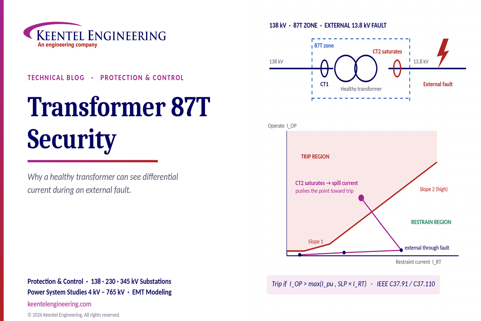
Learn why transformer differential relays detect current during external faults, how CT saturation causes spill current, and how secure 87T protection prevents trips.
By SANDIP R PATEL
•
October 10, 2026
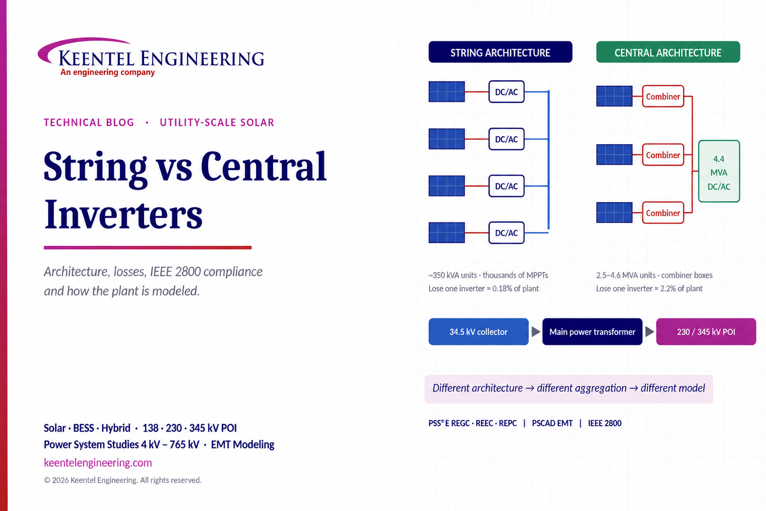
Compare string vs central inverters for utility-scale solar, including efficiency, maintenance, grid compliance, reactive power and interconnection studies.

By SANDIP R PATEL
•
October 3, 2026
Engineering guide to PRC-028 disturbance recording, PRC-029 ride-through and PRC-030 event detection for inverter-based resources.

By SANDIP R PATEL
•
October 3, 2026
A practical guide to SSO classification, SSR, PEDI, Wind-SSCI, EMT analysis, mitigation and protection based on CIGRE TB 909.

By SANDIP R PATEL
•
October 3, 2026
Learn ERCOT generator testing for PFR, MOD-025 and MOD-026/027, including staged tests, capability verification, dynamic models and field testing.

By SANDIP R PATEL
•
October 3, 2026
Learn how PV string I-V curve testing identifies hidden solar performance losses, including soiling, shading, mismatch, degradation, and wiring faults.





