A Coordinated Electric System Interconnection Review—the utility’s deep-dive on technical and cost impacts of your project.
Challenge: Frequent false tripping using conventional electromechanical relays
Solution: SEL-487E integration with multi-terminal differential protection and dynamic inrush restraint
Result: 90% reduction in false trips, saving over $250,000 in downtime
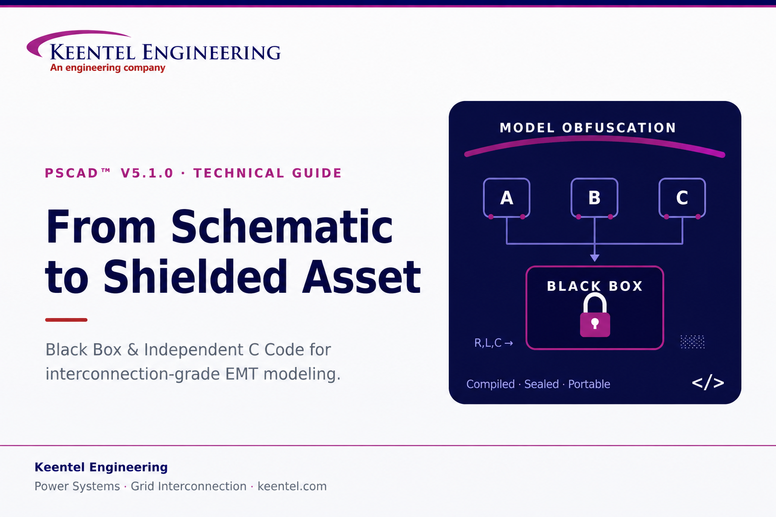
PSCAD™ V5.1.0 Black Box and Independent C Code
A Field Guide for Interconnection-Grade EMT Work
May 20, 2026 | Blog
Electromagnetic transient (EMT) models have become the currency of modern interconnection. Every time an inverter-based resource, an HVDC link, a STATCOM, or a large electronic load is brought to a point of interconnection, the studies that decide whether it can connect—and under what conditions—increasingly hinge on EMT-domain analysis performed in PSCAD™/EMTDC™. That shift has created two practical problems that have very little to do with the physics of the model and everything to do with how the model is handled: how do you share a model without giving away the proprietary control logic inside it, and how do you take control logic you have validated in simulation and put it to work outside the simulator entirely?
PSCAD’s V5.1.0 release answers both questions directly. The Black Box feature lets you collapse an entire module hierarchy into a single, compiled, non-module component—preserving exact behavior while hiding the source. The Independent C Code feature (often called the C Coder) does the inverse for controls: it translates a control module into portable, standalone C that compiles outside PSCAD, including onto bare-metal hardware. At Keentel Engineering, we work with both sides of this exchange every week—receiving obfuscated vendor models on the study side, and helping clients package and port their own logic on the development side. This guide explains what each feature actually does, where the sharp edges are, and how we use them in interconnection-grade work.
Why this matters for interconnection
ISOs and transmission owners increasingly require validated EMT models for IBR and large-load studies, and OEMs are understandably unwilling to expose their control IP. Black Box is the mechanism that squares that circle—letting a developer hand over a model that runs identically without revealing the schematic underneath. Understanding exactly
what an obfuscated model still exposes, and what it does not, is a core competency for anyone running or reviewing those studies.
Part 1 — The Black Box Feature: Obfuscation Without Compromise
The Black Box algorithm automates the complete conversion of a PSCAD page-module hierarchy into a user-defined component. It is not a cosmetic wrapper; it regenerates the model as compiled machine code and rebuilds the component around it. Three things happen under the hood, and it is worth understanding each because they determine what the recipient of a black-boxed model can and cannot see.
What the algorithm actually produces
1. Fortran source generation
Black Box emits Fortran source formatted specifically to run with EMTDC as an external file. This is the same fundamental code path EMTDC uses internally, but the algorithm formats it with the subroutine structure needed for multiple-instance compatibility—so the resulting component can be dropped into a schematic more than once without symbol collisions.
2. Automatic object or library file creation
Optionally, the generated source is compiled into an object file. If the module being black-boxed contains nested modules, every resulting object file is bound together into a single static library. This compiled artifact is where the real protection lives: once the logic is machine code in a .lib, the original source is no longer recoverable from the deliverable.
3. Automatic component creation
Finally, a component definition and instance are built from the contents of the hierarchy—automatically carrying over every port, parameter, graphic, and relevant script segment. The end result looks and connects like any native PSCAD component, but its internals are sealed.
Two restrictions you must plan around
Runtime objects are not supported. Switches, sliders, dials, and radio links cannot survive the Black Box operation, because they imply live user interaction that a compiled component cannot expose in the same way. Before you run the tool, you have to deal with them, and you have exactly two choices:
- Bake in a fixed value. Replace the dial or slider inside the module with a constant tag set to a preset value. This is clean and simple, but it permanently locks that value into the component—there is no real-time variability left once it is sealed.
- Preserve real-time control. Move the control or radio link out of the module entirely. If the object is buried deep in the hierarchy, you must promote its signal upward through every intermediate level using ports or parameters until it reaches the top. The control then lives outside the schematic and drives the finished Black Box component as an external input—retaining live adjustability.
Keentel practice note
Decide the bake-in-vs-promote question before you build the hierarchy, not after. Promoting a deeply nested radio link through five module levels late in a project is tedious and error-prone. If a parameter needs to remain operator-adjustable in the delivered model—a fault-ride-through enable, a control mode selector, a gain trim—design its signal path to the top level from the start.
Transmission lines and cables: new in V5.1.0, and worth understanding
V5.1.0 extended Black Box to systems that include transmission lines and cables—a meaningful addition, because line and cable models carry solved segment data that has to go somewhere. The algorithm embeds the solved transmission-segment information inside the automatically generated subsystem script. The tower and cable configurations themselves stay fully hidden, but a portion of the solved data remains visible, and exactly how much depends on the line model you chose.
This distinction matters for IP protection, so it is worth being concrete about what leaks through each model type:
| Line model | What remains visible to the recipient | Practical exposure |
|---|---|---|
| Bergeron | Steady-state frequency (e.g. 60 Hz), line length (e.g. 100 km), phase count (3-phase), plus impedance and admittance data | Higher — the basic electrical character of the segment is readable |
| Frequency-Dependent (Phase) | Line length and phase count only; remaining data is the poles and residues from the curve-fit | Lower — pole/residue tables are largely indecipherable to an outsider |
The takeaway is straightforward: if hiding the transmission-segment design is a priority, the frequency-dependent phase model exposes far less usable information than Bergeron. We factor this into how we advise clients on model packaging when line topology is itself considered sensitive.
Inside the Options panel: the settings that actually change your model
When you generate a Black Box, an Options dialog appears. You can also set these preferences globally in PSCAD’s main application options, where they save to your user profile—worthwhile if you black-box frequently. Most settings are self-explanatory; the ones below are the ones that change behavior, results, or protection, and they are the ones we pay attention to.
Code Script Usage Compatibility
This ensures the component’s internal definition script is compatible with a target PSCAD version. The critical caveat: it affects only the definition script, not the generated Fortran source. If you build a Black Box in 5.1 using subroutines from the 5.1 master library, setting compatibility back to 4.5 will not make it run in 4.5—that older version simply lacks the newer EMTDC master-library models. Compatibility flags do not back-port capability.
Feed Forward Signal Storage
Leave this on Force Disabled unless you have a specific reason not to. Choosing Assume Current Project Setting inherits the project’s “Store Feed Forward Signals for Viewing” state; if that is enabled, every feed-forward signal is read from and written to storage on every time step inside the generated Fortran. That can hurt code efficiency and simulation speed. However, there is a real failure mode here: some custom models read and write storage improperly, and Force Disabled can change simulation results once the Black Box replaces the original module.
A quick diagnostic before you seal a module
Run the project once with “Store Feed Forward Signals for Viewing” enabled, then again disabled (or vice-versa). If the simulation results change between the two runs, the module is storage-sensitive—select Assume Current Project Setting before you Black Box, then re-run the tool. This five-minute check routinely prevents a black-boxed component from quietly behaving differently than the module it replaced.
Inner component definitions — a bottom-up algorithm
Black Box processes a hierarchy from the bottom up. Picture a top module Top containing A, B, and C; A contains D; C contains E and F; and E contains G. The algorithm walks upward like this:
- Black-box G first; its instance inside E is replaced by the new component.
- Move up to E and F; both are processed and replaced inside parent C.
- Black-box D, replacing its instance inside A.
- Black-box the intermediate modules A, B, and C, replacing each inside Top.
- Finally, black-box Top itself.
The Inner Component Definitions option decides what happens to those intermediate definitions (A through G). Keep them all if you want to reuse the individual children later; otherwise set Do Not Retain and PSCAD deletes the intermediates once the top-level operation finishes, keeping your project tree clean.
Component instance, parameters, and electrical ports
- Component Instance Creation — choose Create New Instance to attach the finished component to your cursor for placement, or Generate Definition Only to build it quietly in the project tree for later manual placement.
- Parameters — Obtain from Source Module Instance copies every preset value from the original module onto the new component (so a module with 20 custom-set parameters transfers seamlessly and runs immediately). The alternative reverts each parameter to its original default.
- Fixed and Switched Electrical Port Names — internal electrical nodes are exposed as fixed and switched ports. Ten fixed nodes, for example, create a ten-element fixed-port array (NBBF). You may rename these internal ports for clarity, or leave the defaults.
- Definition Labels — comma-separated labels that categorize the component on the Models ribbon tab and integrate with the V5.1 Library Viewer pane—useful for keeping a growing library of custom tools organized.
Global substitutions
If your hierarchy calls global substitutions, you choose how they are handled:
- Embed Values — bakes the current substitution values directly into the component as literals. Once sealed, they are permanently locked.
- Make Accessible as Parameters — converts them into component parameters under a new “Global Substitutions” category in the component properties dialog, so you can keep adjusting them exactly as before.
Passive Elements Obfuscation — the heart of circuit protection
This setting is the one that most directly hides proprietary circuit design. Enabling Replace with Runtime Configurable Passive Branch tells PSCAD to use a master-library component model to secure your data: the algorithm strips the specific R, L, and C values out of each electrical branch and moves them into the Fortran file as literal values. Because that Fortran is then compiled into an object or library file, the true values are completely protected. In the final compiled data file, the real component values are replaced by dummy values. The recipient can still see that an RL branch exists in the graphic—but the actual values are hidden.
Transmission segment names, resources, and compilation
- Transmission Segment Names — replaces real line and cable names with generic placeholders such as Tline1 or Cable1 to further obscure proprietary topology. The base prefix is customizable (default: “Segment”).
- Resource Folders — if unspecified, generated files land in the active project folder and clutter it fast. Point this to a dedicated directory (for example a Blackbox folder under your local temp path) to keep generated output organized.
- Binary Files Compilation — generate source only, compile with your current default compiler, or generate objects for every installed compiler at once. Because object, library, and .o files are bound to the exact compiler that produced them, building for all installed compilers is smart practice if you switch compilers regularly.
- Append Resource Files — automatically attaches generated binaries and source to the project’s resources branch, so you can black-box a module, swap it into the schematic, and run immediately. Choose No Action to skip the automation.
- Clear Existing Resources — a maintenance utility that purges the resources branch before appending new files, preventing a pile-up of stale libraries if you black-box often.
- Naming Prefix — a strict requirement. The prefix is prepended to generated subroutines so they stay globally unique. Without it, two libraries that each define a subroutine named, say, “x” will trigger a multiple-source error and the Fortran compile will fail. A distinct prefix removes that risk entirely.
Walkthrough and verification: trust, then verify
Consider a simple RectifierAC page module containing a basic source and an RL load. Right-click, choose Generate Black Box, set a destination folder, and confirm. One best practice governs everything here:
Compile clean first
Black Box uses the exact same netlist compiler PSCAD uses to build a project. So compile the project normally and resolve every existing error before you black-box anything. Sealing a module that already has build errors only drags those errors into the generation process.
After the operation, the destination directory holds a new folder named for the original definition module. Inside is a Fortran source file with the Black Box name appended—structured like a standard EMTDC-generated file but formatted with the subroutines needed for multiple-instance use. The libs folder contains compiler-dependent output: with GFortran, for instance, an object file is produced and automatically bound into a static .lib, which PSCAD labels with the compiler name for later compatibility.
The finished component is where verification happens. Its graphic shows a three-element port array, matching the three fixed nodes in the original module. The underlying script generates the DSDYN and DSOUT calls into the compiled rectifier subroutine and places all branch and node numbers into storage. The original network’s nine branches each appear as a single line in the branch segment—and because passive-branch hiding was enabled, dummy values stand in for the real R, L, and C. With no transformers or model-data components present, those segments are simply empty. The component behaves exactly as the module did, while its design is sealed.
Part 2 — The Independent C Code Feature: Controls Beyond the Simulator
Where Black Box keeps a model inside PSCAD but hides it, the Independent C Code feature does the opposite—it takes a control module out of PSCAD entirely. It translates a PSCAD control module into valid, standalone C that compiles separately from PSCAD for any purpose, including running directly on a microcontroller. For teams that prototype control logic in simulation and then need it on real hardware—hardware-in-the-loop rigs, embedded controllers, digital twins—this closes the gap between the model and the device.
A concrete example
Take a small module with two inputs and one output that computes the running ramp-up over time of sin(input 1) × input 2, added to its previous value, with a parameter to reset the accumulated sum. In simulation, the inputs come from a function of time and slider values—a Reset Time slider sets when the sum resets, and a Gain slider sets the multiplier. Running the case shows the output responding to those inputs. The goal is to lift exactly this logic out of PSCAD and run it elsewhere.
Generating the code and choosing data types
Right-click the module and choose Generate → Independent C Code. A dialog lets you pick the data types the generated C will use—important because target hardware often supports only certain types. You configure three families:
| Type family | Available options (typical width) | PSCAD default |
|---|---|---|
| Integer | short (16-bit), int (32-bit), long long (64-bit) | 32-bit int |
| Floating point | float (32-bit), double (64-bit), long double (128-bit) | 64-bit double |
| Complex | No Complex, C99 standard complex, or struct-based (e.g. MSVC) | — |
The complex-number options exist because many C compilers do not support complex types at all (hence No Complex), some support the C99 standard, and others—the Microsoft Visual C compiler among them—implement complex values through a structure rather than a native type. Once the types are set, click OK to generate.
What gets generated, and where
The output lands in the case’s current temporary build directory, organized into three folders:
- Libs — contains pscadlib.h and pscadlib.c, holding source for all C-export-enabled PSCAD components, with every data-type version of each needed function. The source is provided so you can modify or strip out code you don’t need for a particular compiler.
- Headers — auto-generated header files for calling the module code—one per module compiled (including sub-modules), each named to match its module-definition source.
- Source — the C implementation for each module, again one file per module, named to match the definition.
Using the generated code
A typical integration—say, a Visual Studio 2022 program that reads input from standard-in and writes output to standard-out—follows a consistent pattern. Include every header and source file from the generated output in your project, then wire up the call:
- Include the main header. Its name is the exported module-definition name with a .h extension.
- Declare a void pointer, initialized to null, for application memory. Even though it is a pointer, memory is statically allocated by default—so the code runs on hardware that forbids dynamic allocation. The pointer is bound to the static storage structure the first time the code is called.
- Use the module’s I/O structure. Imported from the module header, its name is the module-definition name followed by _main; it carries inputs in and outputs out.
- Assign inputs, then call the run function. Its name is always the module-definition name followed by _run. It takes a pointer to the void application-memory pointer, an integer run-type, and a pointer to the I/O structure.
- Read the output from the I/O structure,
then loop. On the first call, a null memory pointer triggers allocation, value initialization, and the first time step.
The run-type integer takes one of three values:
| Run type | Meaning |
|---|---|
| 0 | Standard run — execute this time step normally |
| 1 | Last time step — complete this step, then clear memory |
| 2 | Cleanup only — the last step already occurred; clear memory without running |
When the end time is not known in advance—as in a console program that runs until it reads a “Q”—you typically use only 0 during the loop and a single 2 at shutdown to release resources cleanly. (Passing 1 instead would run one final time step on the current I/O before cleanup.) By default the generated algorithm runs in real time, querying the system clock on each call—worth remembering when you benchmark or when deterministic timing matters.
Static versus dynamic allocation
Static allocation is the safe default for constrained hardware, but some situations call for dynamic memory—most commonly when you need multiple instances of the generated code running at once, or when the target allows dynamic allocation but caps static allocation. A small, well-defined edit to the generated source switches modes:
- In the run function, remove the statically allocated structure (named application_memory) declared just above it.
- Replace the two uses of that application memory with a call to malloc, passing the size of the structure.
- Add a call to free for the pstate variable in the two places where it is set to null, before it is nulled.
With those changes, the module runs on dynamic memory and multiple instances can coexist in one application. Document the edit—because it is a manual modification to generated code, it must be re-applied whenever the module is regenerated.
Limitations: know what will and won’t export
The C Coder supports a deliberately bounded set of components. Two conditions must hold: the component must have no electrical aspect (it must be purely controls-based), and the mathematics behind it must not be proprietary to PSCAD. Within those bounds:
| Supported | Not supported |
|---|---|
| Constant and Time components | PID controller |
| Data-type conversion components | Discrete wavelet transform |
| Most CSMF (continuous system model function) components | FFT and harmonic distortion calculator |
The unsupported components are excluded either because their implementation is proprietary or because they need additional detail that cannot be expressed generically. To check any component yourself, open its definition, look at the Scripts section, drop down the current-segment box, and select C. If a C script section exists, the component is C-Coder-ready.
Extending the C Coder with custom components
If a module includes a custom component you need to export, you can make it C-Coder-compatible by giving it a C script section. Edit the component definition, open the Segment Manager, add and highlight the C section, then switch the current segment to C. The code you place there is written verbatim by the C Coder, so it must be valid C—semicolons and all—outside of directives and substitutions. It is auto-indented when written to the C files.
The C script section uses the same control directives as other script sections, plus a few specific to C export:
- Control flow & structure: if / else / elseif / case, and begin, endbegin, top, and bottom—which retain their meaning from the Fortran script sections.
- Function placement: dsdyn / enddsdyn force code into the DSDYN function; dsout / enddsout force it into the DSOUT function.
- Includes: header declares a C #include for a header file; include pulls in script-section code (with its own directives and substitutions) from an external source.
- local — defines a local variable. It works much like the Fortran version, except the variable must be accessed using dollar-sign ($) substitution.
- stash — defines a variable that persists across the program’s execution—the C-export equivalent of the storage arrays used in Fortran sections. Stashed variables are also accessed with $ substitution.
- struct & symbol — both local and stash accept a struct keyword plus a structure name (you define the structure in the included C code), and symbol defines your own substitution for use within the section.
Once the C script section is defined, regenerate the independent C code; you can inspect the result directly in the generated module .c file. The component is then a first-class citizen of the C Coder workflow.
How Keentel Applies These Features
These are not abstract capabilities for us. On the study side, we routinely receive black-boxed EMT models from equipment vendors and developers, and a real part of model-quality review is knowing precisely what an obfuscated model still reveals—line lengths, phase counts, the presence (but not the values) of passive branches—and what it has genuinely sealed. That knowledge shapes how we validate a model we did not build and how we communicate residual exposure to a client who is handing their IP to a third party.
On the development side, we help clients package their own intellectual property for distribution to ISOs, transmission owners, and study consultants without surrendering control design. And when validated control logic needs to leave the simulator—for hardware-in-the-loop testing, embedded deployment, or a digital twin running alongside the physical asset—the C Coder path lets that logic move from PSCAD to silicon with its behavior intact. Used together, Black Box and Independent C Code turn a PSCAD schematic into something you can protect, deliver, and deploy.
Talk to Keentel
Need to package an EMT model for interconnection submission, review an obfuscated vendor model, or port control logic to hardware?
Keentel Engineering provides power-system studies, POI interconnection engineering,
EMT modeling, and owner’s-engineer services across utility-scale renewables, BESS, and
large-load
projects. Reach us at keentel.com to discuss your model-delivery or controls-export workflow.
About Keentel Engineering & Disclaimers
Keentel Engineering is a power systems and grid-interconnection firm with offices in Tampa, Florida and Austin, Texas. Our services span power system studies (EHV/HV/MV), point-of-interconnection engineering, substation and transmission-line design, utility-scale renewables and BESS engineering, owner’s-engineer services, and NERC O&P compliance, with deep EMT-modeling capability across interconnection workflows.
Non-affiliation and trademark notice
This document is an independent technical commentary prepared by Keentel Engineering for educational purposes. Keentel Engineering is not affiliated with, authorized by, sponsored by, or endorsed by Manitoba Hydro International Ltd. PSCAD™ and EMTDC™ are trademarks of Manitoba Hydro International Ltd. All product names, features, and trademarks referenced herein are the property of their respective owners and are used for identification and descriptive purposes only.
Feature descriptions reflect PSCAD V5.1.0 as understood at the time of writing. Software behavior may change across versions; always confirm against the official PSCAD Application Help (including the “Black Boxing Modules” section) and the vendor’s current documentation. For software support, refer to the official PSCAD support channels. This material does not constitute professional engineering advice for any specific project; engagement of a licensed engineer is recommended for project-specific application.
Technical FAQ
Common questions we field on PSCAD V5.1.0 Black Box and Independent C Code, answered from a study-and-delivery perspective.
Black Box
Q. What does Black Box actually protect, and what does it leave exposed?
A. Black Box compiles your module hierarchy into machine code, so the source logic itself becomes unrecoverable from the deliverable. What can still be visible depends on settings and model choices: with passive-branch obfuscation enabled, a recipient sees that an RL branch exists but not its values; with transmission lines, some solved segment data remains readable. It protects the design, not necessarily the existence, of every element.
Treat it as strong protection for control logic and component values, and partial protection for circuit topology unless you also enable segment-name obfuscation and choose a line model that exposes less.
Q. Does a black-boxed component behave identically to the original module?
A. It should, and verifying that is part of using it responsibly. The most common cause of a behavioral difference is feed-forward signal storage in storage-sensitive custom models. Run the project with “Store Feed Forward Signals for Viewing” enabled and then disabled; if results differ, select Assume Current Project Setting before black-boxing. Otherwise the default Force Disabled can change results once the component replaces the module.
Q. Why won’t my sliders, dials, or switches survive the operation?
A. Runtime objects—switches, sliders, dials, and radio links—are not supported because a compiled component cannot expose live interaction the same way a schematic does. You either bake in a fixed value (replace the control with a constant tag, permanently locking it) or preserve real-time control by promoting the signal up through ports/parameters to the top level so it can drive the component as an external input.
Q. Which transmission-line model hides the most information?
A. The frequency-dependent (phase) model. A Bergeron segment exposes steady-state frequency, line length, phase count, and impedance/admittance data. A frequency-dependent phase model exposes only line length and phase count; the rest is the poles and residues from the curve-fit, which are largely indecipherable to an outsider. If line topology is sensitive, prefer the phase model and enable transmission-segment-name obfuscation.
Q. Can I build a Black Box in 5.1 and run it in an older PSCAD version?
A. Not by using the compatibility setting alone. The Code Script Usage Compatibility option affects only the definition script, not the generated Fortran. If your model relies on master-library models that exist only in 5.1, an older version simply lacks them, and setting compatibility back will not create that capability. Plan version targets around the master-library content you actually use.
Q. What does the Naming Prefix do, and can I skip it?
A. You cannot skip it—it is a strict requirement. The prefix is prepended to generated subroutines to keep them globally unique. Without it, two libraries that each define a subroutine of the same name (for example, “x”) will cause a multiple-source error and a failed Fortran compile. A distinct prefix per black-boxed library eliminates that risk.
Q. Should I compile for one compiler or all of them?
A. If you switch compilers, generate objects for all installed compilers at once. Object, library, and .o files are bound to the exact compiler that produced them, so a single-compiler build will not link under a different toolchain. Building for all installed compilers up front saves you from regenerating later.
Q. Any best practice before I run the tool?
A. Compile the project cleanly first. Black Box uses the same netlist compiler PSCAD uses to build the project, so resolving all existing compile errors beforehand prevents the tool from inheriting them during generation. Also point the resource folder at a dedicated directory so generated files don’t clutter your project folder.
Q. What happens to the intermediate child modules in my project tree?
A. Your choice. The algorithm works bottom-up, replacing each child with a black-boxed instance as it climbs. The Inner Component Definitions option lets you retain all intermediate definitions (if you want to reuse those children independently) or Do Not Retain, in which case PSCAD deletes them after the top-level operation to keep the tree clean.
Independent C Code (C Coder)
Q. What is the C Coder for?
A. It translates a PSCAD control module into standalone, valid C that compiles outside PSCAD—for use in external programs or directly on a microcontroller. It is the bridge from simulation-validated control logic to hardware-in-the-loop testing, embedded controllers, and digital twins.
Treat it as strong protection for control logic and component values, and partial protection for circuit topology unless you also enable segment-name obfuscation and choose a line model that exposes less.
Q. Which components can be exported to C?
A. Only components that are purely controls-based (no electrical aspect) and whose underlying mathematics is not proprietary to PSCAD. Supported components include Constant and Time, data-type conversion components, and most CSMF components. Not supported: the PID controller, discrete wavelet transform, FFT, and harmonic distortion calculator, among others with proprietary or non-generic implementations.
Q. How do I check whether a specific component will export?
A. Open the component’s definition, go to the Scripts section, drop down the current-segment box, and select C. If a C script section exists for that component, it is C-Coder-ready. If not, it either isn’t supported or needs a custom C script section added.
Q. How do I configure data types, and why does it matter?
A. The generation dialog lets you choose integer width (short 16-bit, int 32-bit, long long 64-bit; default 32-bit), floating-point type (float 32-bit, double 64-bit, long double 128-bit; default 64-bit double), and complex handling (No Complex, C99 complex, or struct-based for compilers like MSVC). It matters because target hardware and compilers often support only certain types—matching them avoids portability problems downstream.
Q. What do the three run-type values mean?
A. When you call the generated run function, the integer run-type tells it what to do: 0 is a standard time step; 1 completes a final time step and then clears memory; 2 clears memory without running a step (used when the last step already occurred). In an open-ended loop you generally use 0 throughout and a single 2 at shutdown to release resources.
Q. Is the generated code statically or dynamically allocated?
A. Statically by default, so it runs on hardware that forbids dynamic allocation—the void application-memory pointer is bound to a static structure on first call. If you need multiple instances at once, or the hardware caps static allocation, you can edit the generated source: remove the static application_memory structure, replace its two uses with malloc (sized to the structure), and add free for the pstate variable where it is nulled. Re-apply this edit whenever you regenerate.
Q. Does the generated code run in real time?
A. Yes, by default it queries the system clock on each call to the run function. Keep that in mind when benchmarking or when you need deterministic, non-wall-clock timing—the timing behavior is part of what the generated algorithm does.
Q. Can I make a custom component work with the C Coder?
A. Yes. Edit the component definition, open the Segment Manager, add a C script section, and write the component’s C implementation there. It must be valid C outside of directives and substitutions. You have access to control directives (if/else/elseif/case, begin/endbegin/top/bottom), function-placement directives (dsdyn/enddsdyn, dsout/enddsout), include directives (header, include), and variable directives—local and stash (both using $ substitution and both supporting struct), plus symbol for custom substitutions. After defining it, regenerate to inspect the output.
Q. What’s the difference between local and stash variables?
A. A local variable exists within the script section, much like its Fortran counterpart, but is accessed with dollar-sign substitution. A stash variable persists throughout the program’s execution—it is the C-export equivalent of the storage arrays used in Fortran sections—and is also accessed with $ substitution. Use stash when you need state to survive between time steps.
Q. Which PSCAD version introduced these features?
A. The Independent C Code (C Coder) feature was introduced in PSCAD V5.1.0, and that same release extended Black Box support to systems containing transmission lines and cables. Both are V5.1.0 capabilities.

About the Author:
Sonny Patel P.E. EC
IEEE Senior Member
In 1995, Sandip (Sonny) R. Patel earned his Electrical Engineering degree from the University of Illinois, specializing in Electrical Engineering . But degrees don’t build legacies—action does. For three decades, he’s been shaping the future of engineering, not just as a licensed Professional Engineer across multiple states (Florida, California, New York, West Virginia, and Minnesota), but as a doer. A builder. A leader. Not just an engineer. A Licensed Electrical Contractor in Florida with an Unlimited EC license. Not just an executive. The founder and CEO of KEENTEL LLC—where expertise meets execution. Three decades. Multiple states. Endless impact.
Services

Let's Discuss Your Project
Let's book a call to discuss your electrical engineering project that we can help you with.
About the Author:
Sonny Patel P.E. EC
IEEE Senior Member
In 1995, Sandip (Sonny) R. Patel earned his Electrical Engineering degree from the University of Illinois, specializing in Electrical Engineering . But degrees don’t build legacies—action does. For three decades, he’s been shaping the future of engineering, not just as a licensed Professional Engineer across multiple states (Florida, California, New York, West Virginia, and Minnesota), but as a doer. A builder. A leader. Not just an engineer. A Licensed Electrical Contractor in Florida with an Unlimited EC license. Not just an executive. The founder and CEO of KEENTEL LLC—where expertise meets execution. Three decades. Multiple states. Endless impact.
Leave a Comment
We will get back to you as soon as possible.
Please try again later.
Related Posts