
A Coordinated Electric System Interconnection Review—the utility’s deep-dive on technical and cost impacts of your project.
Challenge: Frequent false tripping using conventional electromechanical relays
Solution: SEL-487E integration with multi-terminal differential protection and dynamic inrush restraint
Result: 90% reduction in false trips, saving over $250,000 in downtime
The three operating regions you have to design to
| Device | Output vs voltage | Response | Best suited to | Main limitations |
|---|---|---|---|---|
| Mechanically switched capacitor or reactor | Proportional to voltage squared | Seconds; discrete steps; limited switching operations per day | Steady-state reactive supply, voltage profile, loss reduction | No dynamic capability; step voltage change on switching; capability collapses when most needed |
| Static var compensator | Capacitive branches proportional to voltage squared | A few cycles; continuously controllable | Continuous control where cost matters and deep voltage support is not the driver | Square-law capability loss; harmonic filters are part of the plant and interact with the network |
| STATCOM | Approximately proportional to voltage — constant current capability | One to two cycles closed loop; converter response faster still | Voltage stability margin, weak interconnections, fast disturbance recovery, flicker and unbalance compensation | Higher capital cost; converter losses; adds a converter and its control dynamics to the network |
| Synchronous condenser | Governed by machine capability and excitation | Excitation response in the hundreds of milliseconds; inherent inertial response instantaneous | System strength and inertia, short-circuit contribution, black start support | Rotating plant with maintenance and losses; slower controlled response than a converter |
| STATCOM with energy storage | Reactive as a STATCOM, plus real power within the storage rating | As STATCOM for reactive; real power limited by storage | Where a real power deficiency is part of the problem | Cost and complexity of the storage; different failure and maintenance profile |
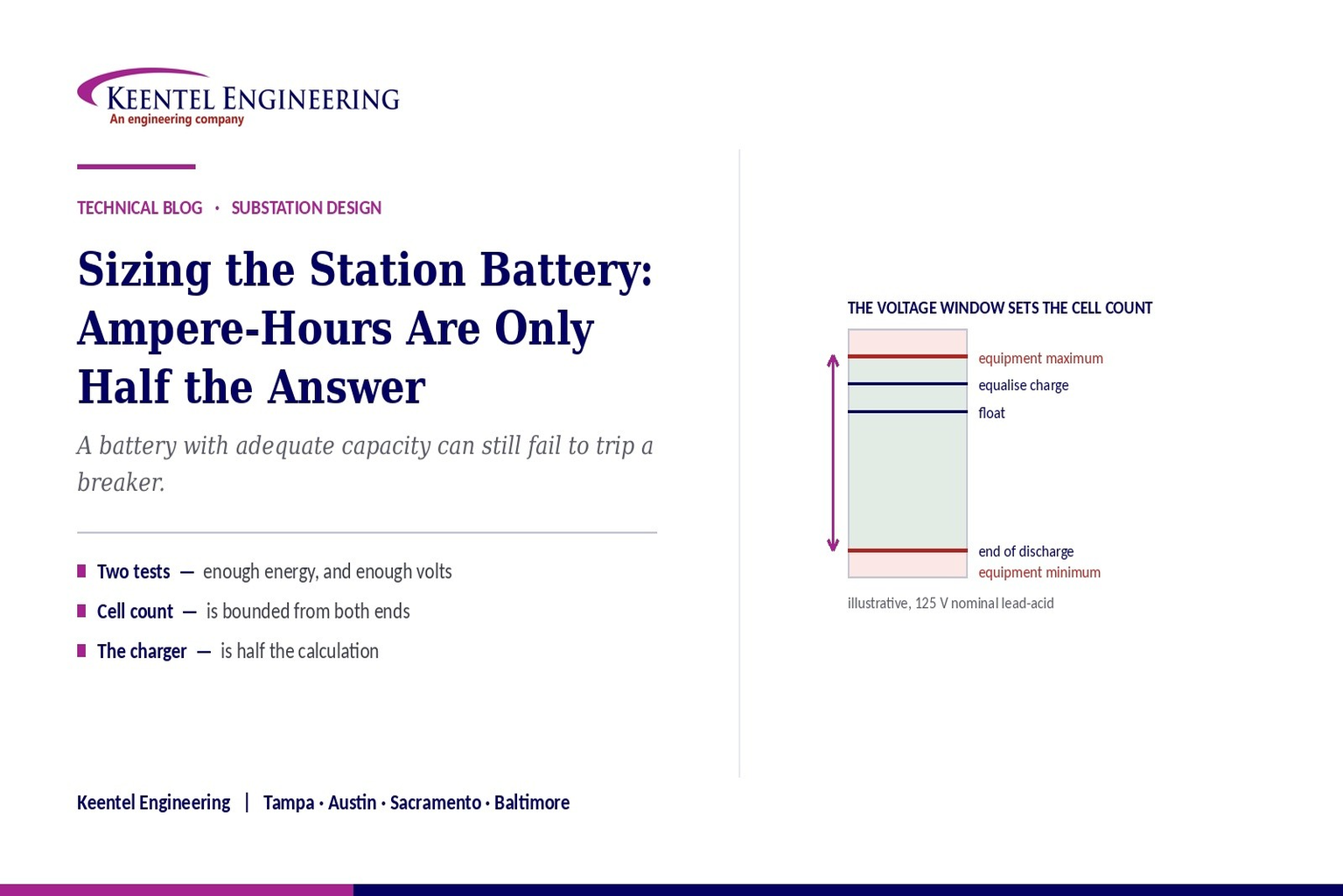
Sizing the Station Battery: Ampere-Hours Are Only Half the Answer
September 3, 2026 | Blog
The Duty Cycle, the Voltage Window, the Charger, and Everything Else That Decides Whether the Breakers Trip When the Station Loses AC
1. Executive Summary
The station battery is the least visible and least glamorous item in a substation, and it is the one on which every protective operation depends. When the alternating-current supply is lost, the battery is what trips the breakers, holds up the relays, powers the communications and keeps the control system alive. A substation with a perfectly coordinated protection scheme and an inadequate battery has an uncoordinated protection scheme, discovered at the worst possible moment.
Sizing it is not load multiplied by backup time. The recognised methodology works through the duty cycle section by section, because the governing condition may occur at any point in it, and it applies capacity rating factors that account for the non-linear relationship between discharge rate and available capacity. Correction factors for temperature, age and design margin are then applied to the result.
Two things routinely go wrong, and both are visible in the circulating explanations of the subject. The first is that the sizing calculation gets stated in a form that does not work — the section-by-section summation collapsed into a single product. The second, and more consequential, is that ampere-hours are treated as the whole answer. A battery can have ample capacity and still be unsuitable, because the number of cells and the discharge rate together determine whether terminal voltage stays above the minimum the equipment requires during a high-current event. The cell count is bounded from above by the maximum voltage the connected equipment can tolerate on equalise charge, and from below by the minimum voltage it needs at the end of discharge. That window is narrow, and it — not the ampere-hour figure — is what most often governs.
This paper works through the method as it should be stated, the voltage window, the direct-current voltage drop check that the ampere-hour calculation does not cover, charger sizing, chemistry selection, direct-current system architecture and protection, the ungrounded-system ground fault problem, installation requirements, and the testing regime that is also a compliance obligation. It includes three illustrative case scenarios and a twenty-five question FAQ.
The sentence that matters most
A battery with adequate ampere-hours can still fail to trip a breaker.
Capacity answers "for how long". Cell count, internal resistance and cable drop answer "at what voltage". A design that has only checked the first has checked the easier half.
2. The Battery Has to Pass Two Tests
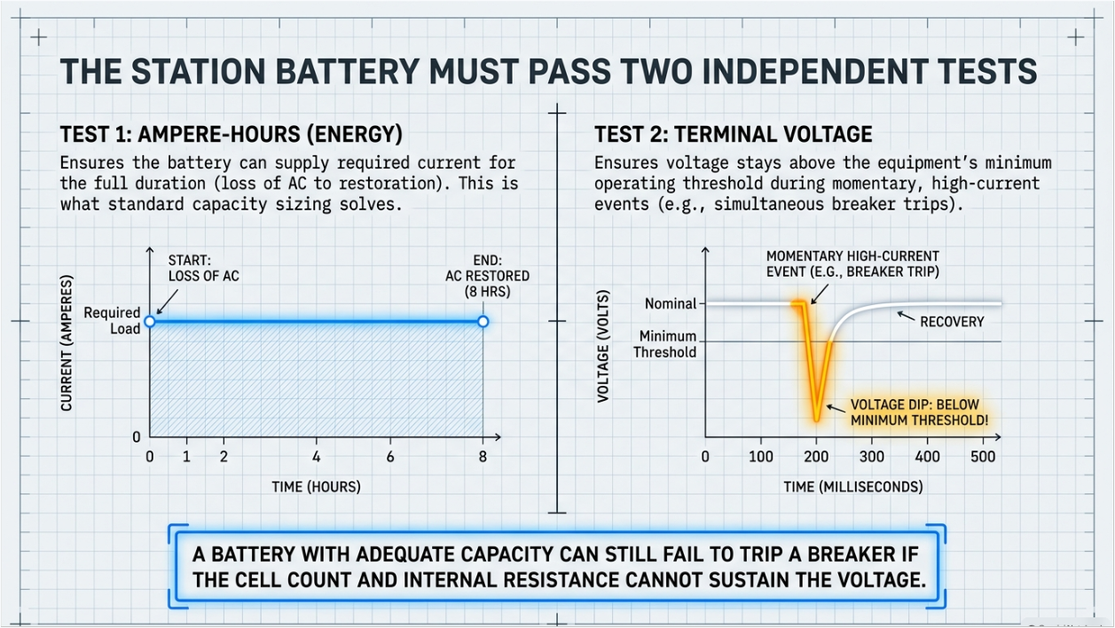
The station battery must satisfy two independent criteria, and satisfying one says nothing about the other.
- The energy criterion. Over the full duty cycle — from loss of alternating current to restoration — the battery must supply the required current for the required duration without exhausting its capacity. This is what the ampere-hour sizing calculation establishes.
- The voltage criterion. At every instant, and particularly during the high-current momentary events, the voltage delivered at the terminals of the connected equipment must remain above the minimum that equipment requires to operate. This depends on the number of cells, the cell’s voltage under the instantaneous discharge rate, and the voltage drop in the direct-current distribution between the battery and the load.
The two are coupled but not equivalent. Adding capacity by selecting a physically larger cell improves both, because a larger cell has lower internal resistance. Adding capacity by paralleling strings improves both as well. But a battery sized purely on ampere-hours, with a cell count chosen from a rule of thumb, can pass the first test and fail the second — and the failure appears as a breaker that does not trip during a simultaneous trip event, which is precisely the event the battery exists for.
3. The Duty Cycle Is the Design
Everything in the calculation follows from the duty cycle, and the duty cycle is an engineering document that has to be assembled from the actual station, not adopted from a template.
3.1 The Three Load Classes
- Continuous loads run for the entire duration: protective relays, control and annunciation, supervisory and remote terminal equipment, communications, inverter loads where fitted, and indicating lights. They are modest in current and they run for the whole period, so they dominate the ampere-hour total.
- Non-continuous loads run for part of the duration: emergency lighting, motor-operated valves and pumps, and equipment brought in at defined points in the sequence. Their position within the duty cycle matters, not merely their magnitude.
- Momentary loads last seconds or less but draw very large current: circuit breaker trip and close coils, spring charging motors, isolator operating mechanisms and motor-operated disconnects. They contribute little to the ampere-hour total and they dominate the voltage criterion.
3.2 The Duration and the Sequence
The design duration — commonly eight hours for a substation, sometimes longer for remote or unattended sites — is a reliability decision reflecting how long alternating-current restoration might take. It should be stated in the design basis with its justification.
The sequence matters as much as the duration. The recognised method requires the calculation to be performed for every section of the duty cycle, because the governing section is not necessarily the last one. A large load early in the cycle, with the remaining duration still to be supplied, can size the battery more severely than the total energy would suggest.
3.3 The Random Momentary Load
The method also requires a random momentary load to be considered — the largest momentary load in the station, assumed to occur at the least favourable moment, which is at the end of the duty cycle when the battery is most depleted. The sizing takes the more onerous of the duty cycle with and without this addition. It is a small refinement in ampere-hours and a significant one in the voltage check, and it is absent from most summaries.
4. The Sizing Method, Correctly Stated
The recognised method computes, for each section of the duty cycle, the capacity that section requires, and takes the largest result. Stating it correctly matters, because the abbreviated versions in circulation do not reproduce it.
Within a section, the calculation accumulates the effect of every change in current that has occurred up to that point. For each period, the change in current from the previous period is multiplied by a capacity rating factor corresponding to the time remaining from the start of that period to the end of the section under consideration. Those products are summed across all periods in the section. The section requiring the largest capacity governs.
For each section S: FS = Σ over periods P = 1 to S of (AP − AP−1) × KT Required cell size = max(FS)
The capacity rating factor is not a single number. It is a function of the discharge duration and of the end-of-discharge voltage per cell, obtained from the manufacturer’s published data for the specific cell being considered. It embodies the non-linear relationship between discharge rate and available capacity: a cell discharged rapidly delivers materially fewer ampere-hours than the same cell discharged slowly. Using a factor from a generic curve, or from a different manufacturer’s cell, introduces an error of the same order as the design margin.
The correction worth making explicitly
Abbreviated versions of this method sometimes appear as a single product of a period current and a capacity factor. That is not the method and it does not give the right answer.
The summation of changes in current, each weighted by the factor for its own remaining duration, is the whole point. Without it, a duty cycle with a large early load and a long tail is sized incorrectly.
5. Correction Factors and What Each Is For
| Factor | What it corrects for | Typical treatment | What goes wrong |
|---|---|---|---|
| Temperature | Available capacity falls as electrolyte temperature falls below the reference condition | A multiplier taken from published data at the lowest expected electrolyte temperature, referenced to the standard temperature | Using ambient room temperature rather than the lowest expected electrolyte temperature, or ignoring an unheated battery room in a cold climate |
| Aging | Capacity declines over service life, and the battery must still meet the duty at the end of it | A factor corresponding to the replacement criterion — commonly the reciprocal of the end-of-life capacity threshold | Omitting it, which produces a battery that meets the duty only when new; or applying it to a chemistry whose ageing behaviour differs |
| Design margin | Load growth, uncertainty in the duty cycle, and future additions | A modest additional allowance, commonly in the range of ten to fifteen percent | Treating it as optional, or consuming it immediately with loads that were known at design and simply not listed |
| End-of-discharge voltage per cell | The voltage at which the calculation stops — which determines how much of the cell is usable | Set by the cell count and the minimum system voltage, then used to select the capacity rating factors | Chosen independently of the cell count, so the calculation and the voltage window describe different designs |
The last row deserves emphasis because it is the coupling between the two halves of the problem. The end-of-discharge voltage per cell is not a free choice: it is the minimum system voltage divided by the number of cells. Change the cell count and every capacity rating factor in the calculation changes with it.
6. Cell Count Is Bounded From Both Ends
The cell count is frequently presented as the nominal system voltage divided by the nominal cell voltage. That gives a starting point and it is not the design. The actual constraint is a window bounded by two equipment limits.
6.1 The Upper Bound: Equalise Charging
The connected equipment has a maximum voltage it can tolerate. The highest voltage the direct-current system ever sees is during equalise or boost charging, when the charger is driven above float to correct cell imbalance. The number of cells multiplied by the equalise voltage per cell must not exceed the equipment maximum. On a nominal one hundred twenty-five volt lead-acid system with a typical maximum equipment voltage, that constraint alone bounds the cell count — and a count chosen from the nominal-voltage division can exceed it.
6.2 The Lower Bound: End of Discharge
At the other extreme, the equipment has a minimum voltage below which it will not operate. The number of cells multiplied by the end-of-discharge voltage per cell must not fall below it. Fewer cells means a higher required end-of-discharge voltage per cell, which means less of each cell’s capacity is usable, which means a physically larger cell is needed for the same duty.
6.3 The Trade That Results
The two bounds pull in opposite directions and the window between them is often narrow. More cells improve the discharge end and worsen the charging end; fewer cells do the reverse. The count that satisfies both, with margin, is the design — and it should be documented alongside the voltage assumptions it depends on: float voltage per cell, equalise voltage per cell, end-of-discharge voltage per cell, and the equipment maximum and minimum.
Where the window cannot be satisfied, the options are a different charging regime, equipment with a wider voltage tolerance, dropping devices, or a different chemistry with a different cell voltage. Each is a real engineering decision and each should be taken deliberately rather than by rounding the cell count.
7. Ampere-Hours Do Not Multiply With Series Cells
This deserves its own section because the error appears in circulating material and it is dimensionally serious.
Cells connected in series add voltage. The ampere-hour capacity of the string is the ampere-hour capacity of one cell, not the cell capacity multiplied by the number of cells. A string of sixty cells of two hundred fifty ampere-hours each is a two hundred fifty ampere-hour battery at the string’s nominal voltage. It is not a fifteen thousand ampere-hour battery.
Ampere-hours add when strings are connected in parallel. Energy — in watt-hours — is the product of the string voltage and the string ampere-hour capacity, and that is the quantity that scales with cell count.
The practical consequence of getting this wrong is not arithmetic embarrassment. It is a specification or a bid evaluation in which two batteries are compared on incompatible numbers, and a purchase order for a battery an order of magnitude away from what the duty cycle requires.
8. The Minimum Voltage Check and DC Voltage Drop
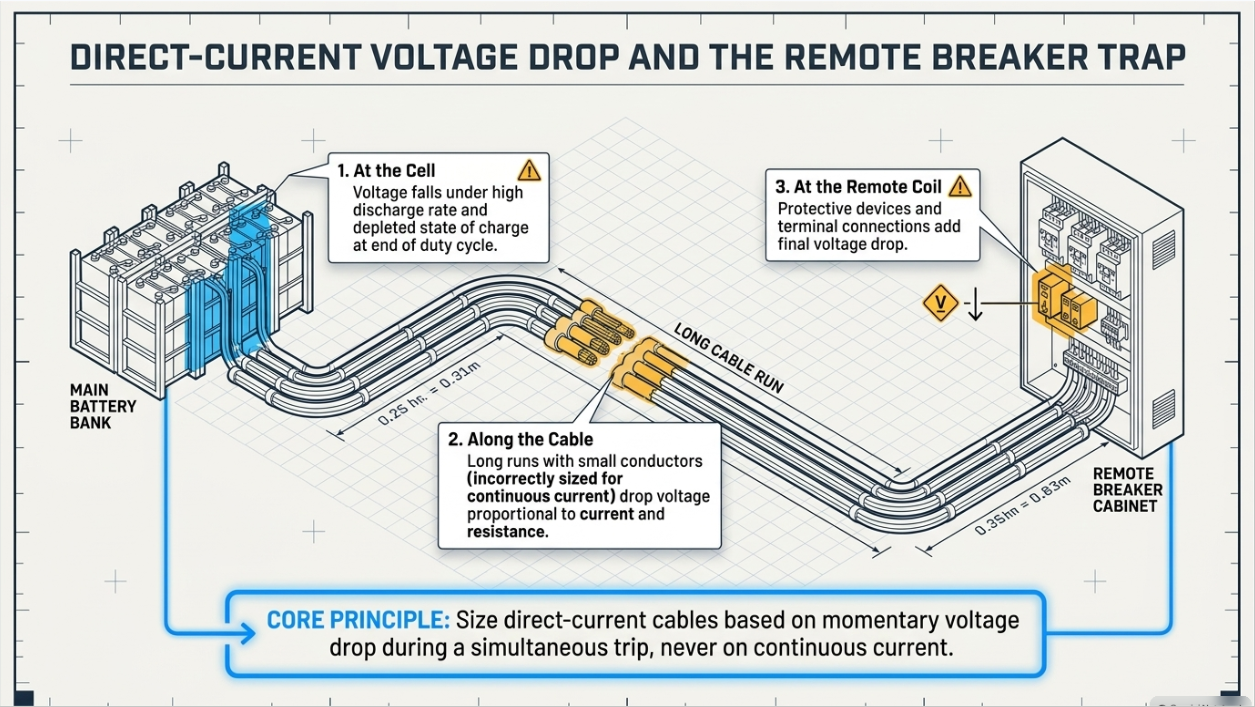
The ampere-hour calculation establishes that the battery has enough energy. It does not establish that the voltage at the load stays high enough, and that is a separate calculation.
During a momentary event — a simultaneous trip of several breakers, or a trip combined with spring charging motors — the instantaneous current can be many times the continuous load. Three things then reduce the voltage the coil actually receives.
- The cell voltage falls under load, by an amount determined by the internal resistance of the cell at that discharge rate and its state of charge. A depleted battery at the end of a long duty cycle has both a lower open-circuit voltage and a higher effective internal resistance.
- The direct-current distribution drops voltage in proportion to current and to circuit resistance. Long cable runs to remote breaker cabinets, small conductors sized for continuous current rather than momentary, and every termination in the path all contribute.
- Protective devices and connections in the path add their own drop.
The check is therefore performed at the worst combination: the largest credible momentary load, at the end of the duty cycle, at the electrically most remote load. If the voltage at that coil falls below its minimum operating value, the breaker does not trip — and the protection scheme that computed a clearing time based on it was wrong.
A design habit worth adopting
Size direct-current cables on the momentary voltage drop, not on the continuous current. Continuous load rarely governs a station direct-current circuit; the trip coil at the far end during a simultaneous trip almost always does.
And state the assumed simultaneous trip scenario explicitly, because it is a judgment about how many breakers can credibly operate at once and it should be reviewed rather than assumed.
9. Charger Sizing: The Missing Half
A battery that cannot be recharged in time is a battery that is unavailable for the next event, and charger sizing is absent from most treatments of this subject.
The charger must simultaneously carry the continuous direct-current load and recharge the battery. Its required output is therefore the continuous load plus the recharge current, where the recharge current is the ampere-hours removed during the duty cycle, increased by a factor accounting for recharge inefficiency, divided by the recharge time required by the design.
Three decisions follow from that and they belong in the design basis.
- The recharge time. A shorter recharge time gives a faster return to readiness and requires a larger charger. Common design values sit in the range of eight to twenty-four hours; the choice reflects how quickly the station must be ready for a second event.
- Charger redundancy. A single charger is a single point of failure on the system that supports every protective operation. Redundant chargers, or a second charger on a common bus with appropriate isolation, is standard for stations where availability matters.
- Charger behaviour and monitoring. Float and equalise voltages, current limit, alarm contacts for charger failure, low voltage, high voltage and ground fault, and how those alarms reach the operator. A failed charger that nobody knows about is a station running on a slowly discharging battery.
10. Chemistry Selection
| Type | Characteristics | Where it suits | What to watch |
|---|---|---|---|
| Vented lead-acid | Long service life, tolerant of float service, gradual and observable capacity decline, electrolyte accessible for inspection and measurement | The traditional substation choice where a dedicated battery room with ventilation and containment is available | Requires ventilation for hydrogen evolution, spill containment, eyewash provision, and regular electrolyte-level and specific-gravity maintenance |
| Valve-regulated lead-acid | Sealed, no electrolyte maintenance, smaller footprint, can be installed in a wider range of locations | Space-constrained sites and installations without a dedicated battery room | Shorter service life, greater sensitivity to temperature, and a failure mode that can be sudden rather than gradual — which places more weight on the testing regime |
| Nickel-cadmium | Very tolerant of temperature extremes, deep discharge and mechanical abuse; long life; predictable end-of-life behaviour | Harsh environments, extreme temperatures, and applications where robustness outweighs cost | Lower cell voltage means more cells for the same system voltage; different sizing methodology; different charging regime; disposal considerations |
| Lithium-based | High energy density, small footprint, integrated management system, different ageing behaviour | Where space or weight governs, and increasingly considered for new installations | Requires a battery management system whose failure modes become part of the direct-current system reliability case; different fire protection considerations; sizing methodology differs from the lead-acid method entirely |
11. DC System Architecture and Redundancy
The battery is one element of a direct-current auxiliary system, and the architecture around it determines how much a single failure costs.
- Single battery and single charger is the minimum arrangement and it makes both a single point of failure for every protective operation in the station.
- A single battery with redundant chargers removes the charger as a single point and is a common and economical improvement.
- Two independent batteries with two chargers, feeding separate direct-current buses, allows the two protection systems in a redundant scheme to be genuinely independent. Where the design intent is that two protection systems are independent, sharing one direct-current supply defeats it — a point worth checking, because it is a common finding.
- Bus arrangement, tie breakers and their operating philosophy determine what happens during maintenance and during a fault on one bus. A tie that is normally closed makes two batteries into one system.
Distribution design matters as much as the source. Selective coordination between the main direct-current protective devices and the branch devices means a fault on one circuit does not remove the whole system. Direct-current circuit protection is its own discipline, and it is covered in the next section.
12. DC Short Circuit, Protection, and Arc Flash
A station battery is a low-impedance source and it delivers very high short-circuit current — frequently many thousands of amperes for a bank of any size. Three consequences follow and all three are routinely under-treated.
- Equipment ratings. Direct-current protective devices, disconnects and busbars must be rated for the available direct-current short-circuit current at their location. Direct current has no natural zero crossing, so interruption is harder and device ratings are specific to direct-current service — an alternating-current rating does not transfer.
- Coordination. Branch device selection and settings must ensure a fault on one circuit clears without removing the whole direct-current system. This is the same selectivity discipline as on the alternating-current side and it is done far less often.
- Arc flash Direct-current arc flash is a real hazard with its own calculation methodology, distinct from the alternating-current approach, and battery work is a recognised exposure. Incident energy at the battery terminals and at the direct-current distribution should be assessed and the results reflected in labelling and work practice.
The short-circuit calculation requires the battery’s internal resistance and the circuit resistance, and manufacturers publish the data. The reason it is skipped is usually that nobody owns it — the battery is procured by one party, the direct-current distribution designed by another, and the fault study performed on the alternating-current system only.
13. Grounding and the Double-Ground Failure
Station direct-current systems are conventionally operated ungrounded, so that a single ground fault does not cause an interruption. That choice creates a specific and well-known failure mode.
A single ground on either pole produces no current and no operational effect. It also produces no symptom unless the system has ground fault detection and somebody responds to it. A second ground on the opposite pole then completes a circuit — and depending on where the two faults sit relative to the trip circuits, the result can be a spurious trip of equipment that should not have tripped, or a short circuit across part of the direct-current system, or a trip circuit that has been shunted and will not operate when called upon.
The last of those is the dangerous one, because it is silent. A trip circuit rendered inoperative by a second ground fault behaves normally until the day it is needed.
The engineering response is straightforward and requires discipline rather than technology: ground fault detection on every direct-current system, alarms that reach an operator rather than a panel nobody looks at, and a maintenance practice that treats a first ground as a defect to be located and cleared promptly rather than a nuisance alarm to be acknowledged. Trip circuit supervision is the complementary measure, because it detects an open or shunted trip circuit directly.
14. Installation: Ventilation, Containment, Seismic
- Ventilation. Vented lead-acid cells evolve hydrogen during charging, and the room must be ventilated to keep the concentration well below the lower explosive limit under the worst-case charging condition. Ventilation is calculated from the charging current and cell count, not assumed, and the calculation belongs in the design record. Valve-regulated cells evolve less but not zero.
- Containment and safety provisions. Spill containment, acid-resistant surfaces, eyewash and drench facilities, and personal protective equipment provision are code requirements as well as good practice for flooded cells.
- Temperature control. Capacity falls with temperature and life falls with elevated temperature, so the room environment is a design parameter with consequences at both ends. An unheated battery room in a cold climate drives the capacity correction; an uncooled one in a hot climate shortens life substantially.
- Seismic qualification. Battery racks in qualifying locations require seismic qualification, and the anchorage and restraint design is a structural item that must be coordinated with the electrical layout rather than added afterwards.
- Access and maintainability. Room layout must permit inspection, measurement, individual cell replacement and eventual whole-bank replacement without dismantling the installation. That is a decision made at design and regretted for twenty years if it is made badly.
15. Testing, Maintenance, and the Compliance Obligation
A battery is a latent-failure device: it sits on float for years and its condition is unknown unless it is measured. That is why maintenance and testing are prescribed rather than optional, and why for registered facilities they are also a compliance obligation.
- Acceptance test. A capacity test performed on the new battery, either at the factory or on site, verifying that the delivered battery meets its rating. Without it, a shortfall present from day one is indistinguishable from later degradation.
- Performance or capacity test. A full discharge at a defined rate, measured and corrected to reference temperature, expressed as a percentage of rated capacity. This is the only test that establishes actual capacity, and the recognised replacement criterion is a defined percentage of rating.
- Service test. A discharge against the actual duty cycle, verifying that the battery can perform the duty it was sized for. It answers a different question from the capacity test and does not replace it.
- Periodic inspection. Float voltage, cell voltages, connection resistance, electrolyte level and specific gravity where applicable, temperature, and visual condition, at the intervals the applicable recommended practice specifies for the chemistry.
- Compliance. For registered facilities, the station direct-current supply is a component of the protection system, so battery maintenance and testing fall within the protection system maintenance obligations, with defined activities, intervals and evidence requirements. The battery is not an ancillary item in that framework — it is part of the protection system.
The pattern worth avoiding is a programme that performs inspections diligently and capacity tests rarely. Float voltage and cell voltages confirm that the battery is being charged correctly; they say very little about how much capacity remains. A battery can present perfect float readings and fail its duty cycle.
16. Case Studies
The following scenarios are composite and illustrative. They are constructed from patterns that recur across substation direct-current systems to show how these failures develop and how they are found. They do not describe any specific client, site, project, manufacturer, or utility.
16.1 Case A — Enough Ampere-Hours, Not Enough Volts
Situation. A substation direct-current system sized by an ampere-hour calculation against an eight-hour duty cycle, with the cell count taken as the nominal system voltage divided by the nominal cell voltage. The battery was correctly sized for energy, met its acceptance capacity test, and operated without complaint for several years.
What the review found
The minimum voltage check had never been performed. Recalculating the terminal voltage at the electrically most remote breaker cabinet during a credible simultaneous trip — at the end of the duty cycle, with the battery depleted — showed the voltage at the trip coil falling below its minimum operating value. Three effects combined: the cell voltage under the momentary discharge rate, the depleted state of charge, and the voltage drop in a long direct-current cable that had been sized on continuous current.
Exposure
A breaker that would not trip during the exact scenario the battery exists to cover. The protection scheme’s clearing times assumed the breaker operates; local backup and remote backup would eventually have cleared the fault, far more slowly, with correspondingly higher equipment damage and incident energy.
Remedy
The direct-current feeder to the remote cabinets was upsized on the momentary voltage drop rather than the continuous current, the cell count and end-of-discharge voltage were re-evaluated against the equipment voltage window, and the simultaneous trip scenario was documented in the design basis so that future additions are checked against it.
Lesson
Ampere-hours answer "for how long". Cell count, internal resistance and cable drop answer "at what voltage". A design that has checked only the first has checked the easier half, and the half that fails is the other one.
16.2 Case B — The Charger That Could Not Catch Up
Situation. A station with a correctly sized battery and a charger selected to carry the continuous direct-current load with a modest allowance. The arrangement performed normally for years, because the station had never experienced an extended loss of alternating-current supply.
What the review found
The charger output had never been checked against the recharge requirement. Following a full duty cycle discharge, recharging the ampere-hours removed — while simultaneously carrying the continuous load and allowing for recharge inefficiency — would have taken far longer than the design basis assumed. For a substantial period after any extended outage, the station would have been operating on a partially charged battery with materially reduced capability for a second event.
Exposure
Reduced availability at exactly the time when a second disturbance is most likely, because the conditions that caused the first outage frequently persist. The condition was invisible in normal operation and would only have manifested during a sequence of events.
Remedy
The charger was replaced with a unit sized on the continuous load plus the recharge current for the design recharge time, a second charger was added for redundancy given the station’s importance, and charger failure, low voltage, high voltage and ground alarms were routed to the operator rather than terminating at a local panel.
Lesson
Battery sizing and charger sizing are one calculation, not two. A battery that cannot be restored to readiness within the design recharge time is a battery that is unavailable for the next event, and the omission does not show up in any routine check.
16.3 Case C — The First Ground Nobody Cleared
Situation. An ungrounded station direct-current system with functioning ground fault detection. A ground fault alarm appeared and was acknowledged. Because an ungrounded system tolerates a single ground without operational effect, the alarm was recorded as a low-priority item and remained open across several maintenance cycles.
What the review found
The first ground had persisted for an extended period. A second ground developing on the opposite pole — in a cable, a terminal block, or a moisture-affected enclosure — would have completed a circuit whose consequence depended entirely on where the two faults sat. Depending on the location, the outcomes ranged from a spurious trip of unfaulted equipment, through a short circuit across part of the direct-current system, to a trip circuit shunted so that it would not operate when called upon.
Exposure
The last of those is silent. A trip circuit rendered inoperative by a second ground behaves entirely normally until the day it is needed, and nothing in routine operation would have revealed it.
Remedy
The first ground was located and cleared, and the maintenance practice was revised so that a direct-current ground alarm is a defect with a defined response time rather than a nuisance alarm to be acknowledged. Trip circuit supervision was reviewed and extended so that an open or shunted trip circuit is detected directly rather than inferred.
Lesson
An ungrounded direct-current system tolerates the first ground fault by design. That tolerance is only safe if the first fault is found and cleared — which makes ground fault detection a maintenance obligation, not merely an alarm point.
17. Reading the Infographic Correctly
The key engineering point is right, and it is the right one to lead with
That adequate ampere-hours are not sufficient, and that voltage must stay above the minimum during high-current events, is exactly the correct headline. Most treatments of this subject never get there.
The sizing formula as abbreviated does not work
The method sums, for each section, the changes in current weighted by the capacity rating factor for their own remaining durations, and takes the maximum across sections. Compressing that to a single product of a period current and a factor discards the part that makes it correct.
Ampere-hours do not multiply by the number of series cells
A string of series cells has the ampere-hour capacity of one cell at the string voltage. Multiplying cell count by cell ampere-hours produces a number with no physical meaning, and it is a dimensional error rather than an approximation.
Cell count is not the nominal voltage divided by the nominal cell voltage
That division is a starting point. The count is bounded above by the equipment maximum voltage during equalise charging and below by the equipment minimum voltage at end of discharge, and the window between them is often narrow enough to be the governing constraint.
Charger sizing is missing
A battery that cannot be recharged within the design recharge time is unavailable for the next event. The charger must carry the continuous load and the recharge current simultaneously, and the calculation is part of the same design.
The standards list reflects a different market
Alongside the international battery sizing standards, the circulating material cites national standards from a market outside North America. A specification for a project in the United States should reference the applicable American standards for sizing, installation, maintenance and testing, together with the electrical code article covering storage batteries and, for registered facilities, the protection system maintenance obligations.
18. Keentel Substation Design Services
Substation design is core practice at Keentel Engineering and the direct-current auxiliary system is one of the areas where design quality is least visible and most consequential.
18.1 DC Auxiliary Systems
- Duty cycle development from the actual station load inventory, including continuous, non-continuous and momentary loads, the random momentary load, and a documented simultaneous operation scenario.
- Battery sizing to the recognised methodology using manufacturer capacity rating data for the specific cell, with temperature, aging and design margin corrections applied and documented.
- Voltage window analysis establishing the cell count against the equipment maximum on equalise and minimum at end of discharge, and the minimum voltage check at the electrically most remote load under the governing momentary scenario.
- Direct-current distribution design and cable sizing on momentary voltage drop, direct-current short-circuit calculation, protective device selection and coordination, and direct-current arc flash assessment.
- Charger sizing for continuous load plus recharge, redundancy configuration, and alarm and monitoring architecture.
- Battery room design including ventilation calculation, containment, safety provisions, temperature control, seismic anchorage coordination and maintenance access.
18.2 Substation Design
- Physical and electrical design for transmission and distribution substations, collector substations and interconnection facilities — single line development, general arrangement, plan and section, equipment layout, bus design and clearances.
- Grounding grid design and step-and-touch analysis from measured soil resistivity, lightning protection and shielding, and insulation coordination.
- Control building and control house design, panel layout, alternating- and direct-current auxiliary systems, station service, and cable and raceway design.
- Protection and control design including scheme development, relay panel and schematic design, settings, and substation automation and communications integration.
- Equipment specification for transformers, switchgear, breakers, instrument transformers, batteries and chargers, with the behavioural and test requirements that make a specification enforceable.
18.3 Studies and Compliance
- Short-circuit, protective coordination and selectivity, and arc-flash studies on both the alternating- and direct-current systems.
- Load flow, harmonic and power quality studies, grid strength assessment, transient stability, and electromagnetic transient analysis.
- NERC compliance support including protection system maintenance programmes, in which the station direct-current supply is a protection system component with its own testing and evidence obligations.
18.4 Owner’s Engineer, Commissioning, and Assessment
- Design review of EPC and vendor submittals and QA/QC of third-party design and study packages.
- Commissioning specification and test procedure development including acceptance capacity testing, service testing, and verification of the minimum voltage condition under a realistic momentary load.
- Condition assessment of existing direct-current systems, including re-verification of the sizing basis against the current load inventory — which has usually grown since the original design.
Keentel Engineering holds a Florida Certificate of Authorization and maintains offices in Tampa, Austin, Sacramento, and Baltimore, supporting projects across the interconnections.
19. References and Further Reading
The following are referenced by subject in the body of this document. The current published edition of each standard governs its own requirements, and the manufacturer’s published data for the specific cell governs any sizing calculation.
Sizing and System Design
- IEEE Std 485, Recommended Practice for Sizing Lead-Acid Batteries for Stationary Applications — the section-by-section duty cycle method, capacity rating factors, and the temperature, aging and design margin corrections — IEEE Standards Association
https://standards.ieee.org/ - IEEE Std 1115, Recommended Practice for Sizing Nickel-Cadmium Batteries for Stationary Applications — IEEE Standards Association
https://standards.ieee.org/ - IEEE Std 946, Recommended Practice for the Design of DC Auxiliary Power Systems for Generating Stations — the overall direct-current system design reference including charger sizing, distribution, grounding and protection — IEEE Standards Association
https://standards.ieee.org/ - IEEE Std 1375, Guide for the Protection of Stationary Battery Systems — IEEE Standards Association
https://standards.ieee.org/
Installation, Maintenance, and Testing
- IEEE Std 484, Recommended Practice for Installation Design and Installation of Vented Lead-Acid Batteries for Stationary Applications, and IEEE Std 1187 for valve-regulated installations — IEEE Standards Association
https://standards.ieee.org/ - IEEE Std 450, Recommended Practice for Maintenance, Testing, and Replacement of Vented Lead-Acid Batteries; IEEE Std 1188 for valve-regulated; IEEE Std 1106 for nickel-cadmium — IEEE Standards Association
https://standards.ieee.org/ - IEEE Std 693, Recommended Practice for Seismic Design of Substations, covering qualification and anchorage of battery racks in qualifying locations — IEEE Standards Association
https://standards.ieee.org/
Code, Safety, and Compliance
- NFPA 70, National Electrical Code — including the article covering storage batteries and the associated ventilation, working space, disconnection and overcurrent protection requirements, and NFPA 70E for electrical safety including direct-current arc flash — National Fire Protection Association
https://www.nfpa.org/ - IEEE Std 1584 for arc-flash calculation methodology on the alternating-current side, with direct-current incident energy assessed by the recognised direct-current methods — IEEE Standards Association
https://standards.ieee.org/ieee/1584/6763/ - NERC Reliability Standards — in particular the protection system maintenance requirements, within which the station direct-current supply is a protection system component with defined maintenance activities, intervals and evidence obligations — North American Electric Reliability Corporation
https://www.nerc.com/pa/Stand/Pages/ReliabilityStandards.aspx
20. Frequently Asked Questions
Q1. Why is battery sizing not just load multiplied by backup time?
Because available capacity depends on discharge rate. A cell discharged rapidly delivers materially fewer ampere-hours than the same cell discharged slowly, and the recognised method accounts for that with capacity rating factors. It also works section by section through the duty cycle, because the governing condition may not be at the end.
Q2. What are the two tests a station battery must pass?
The energy test — enough capacity for the duty cycle — and the voltage test — terminal voltage at the load staying above the equipment minimum at every instant, particularly during momentary events. Satisfying one says nothing about the other, and a battery can pass the first and fail the second.
Q3. What is in the duty cycle?
Continuous loads such as relays, control, supervisory equipment and communications; non-continuous loads such as emergency lighting and motor-operated equipment; and momentary loads such as breaker trip and close coils and spring charging motors. The sequence matters as much as the magnitudes.
Q4. What is the random momentary load?
The largest momentary load in the station, assumed to occur at the least favourable moment — the end of the duty cycle when the battery is most depleted. The sizing takes the more onerous of the duty cycle with and without it. It is a modest ampere-hour addition and a significant one for the voltage check, and it is missing from most summaries.
Q5. What is the correct form of the sizing calculation?
For each section of the duty cycle, sum the changes in current from period to period, each multiplied by the capacity rating factor corresponding to the time remaining from that period to the end of the section; the section requiring the largest capacity governs. Compressing this to a single product of a current and a factor is not the method and does not give the right answer.
Q6. Where do the capacity rating factors come from?
From the manufacturer’s published data for the specific cell, as a function of discharge duration and end-of-discharge voltage per cell. Using a generic curve or another manufacturer’s data introduces an error of the same order as the design margin.
Q7. Why does the temperature correction use electrolyte temperature?
Because capacity depends on the temperature of the electrolyte, not the room air. The correction should be evaluated at the lowest expected electrolyte temperature, which in an unheated room in a cold climate is materially lower than the design ambient people typically use.
Q8. What is the aging factor for?
So the battery still meets the duty at the end of its service life rather than only when new. It corresponds to the replacement criterion — the capacity percentage at which the battery is considered end of life. Omitting it produces a battery that is adequate on day one and inadequate for most of its life.
Q9. Is the design margin optional?
In practice, no. Load inventories grow, duty cycles are never quite complete, and equipment gets added. A modest allowance covers that. What defeats it is consuming it immediately with loads that were known at design and simply not listed.
Q10. How is the number of cells actually determined?
By a window, not a division. The upper bound is the equipment maximum voltage divided by the equalise voltage per cell; the lower bound is the equipment minimum voltage divided by the acceptable end-of-discharge voltage per cell. Dividing nominal system voltage by nominal cell voltage gives a starting point that may violate either bound.
Q11. What happens if I use fewer cells?
The required end-of-discharge voltage per cell rises, so less of each cell’s capacity is usable, so a physically larger cell is needed for the same duty. More cells improve the discharge end and worsen the charging end. The count that satisfies both bounds with margin is the design.
Q12. Does the end-of-discharge voltage per cell affect the ampere-hour calculation?
Directly. It determines which capacity rating factors apply. Change the cell count and every factor in the calculation changes with it, which is why the cell count and the sizing calculation cannot be done independently.
Q13. Does a sixty-cell string of two hundred fifty ampere-hour cells give fifteen thousand ampere-hours?
No. Series cells add voltage; the string ampere-hour capacity is that of one cell. That string is a two hundred fifty ampere-hour battery at the string voltage. Ampere-hours add when strings are paralleled. Energy in watt-hours is voltage multiplied by ampere-hours, and that is what scales with cell count.
Q14. Why can a battery with adequate capacity fail to trip a breaker?
Because three effects combine during a momentary event: cell voltage falls under the high discharge rate, the depleted state of charge lowers it further, and the direct-current cable drops voltage in proportion to current. If the coil at the far end sees less than its minimum operating voltage, it does not trip.
Q15. How should direct-current cables be sized?
On the momentary voltage drop, not on continuous current. Continuous load rarely governs a station direct-current circuit; the trip coil at the electrically most remote cabinet during a simultaneous trip almost always does.
Q16. How is the charger sized?
Continuous direct-current load plus recharge current, where recharge current is the ampere-hours removed during the duty cycle, increased for recharge inefficiency, divided by the required recharge time. A charger sized only for the continuous load leaves the station on a partially charged battery for a long period after any extended outage.
Q17. What recharge time should be used?
A design decision reflecting how quickly the station must be ready for a second event, commonly in the eight to twenty-four hour range. Shorter recharge means a larger charger. State it in the design basis rather than inheriting it.
Q18. Vented or valve-regulated lead-acid?
Vented cells offer longer life, gradual and observable degradation, and accessible electrolyte for inspection, at the cost of a ventilated room with containment and maintenance. Valve-regulated cells are sealed, smaller and more location-flexible, with shorter life, greater temperature sensitivity and a failure mode that can be sudden — which places more weight on the testing regime.
Q19. When does nickel-cadmium make sense?
Where temperature extremes, deep discharge or mechanical robustness govern. It tolerates conditions that shorten lead-acid life considerably and has predictable end-of-life behaviour. The trade-offs are more cells for the same system voltage, a different sizing methodology and charging regime, and disposal considerations.
Q20. Does the direct-current system need a short-circuit study?
Yes. A battery is a low-impedance source delivering very high direct-current fault current. Device ratings must be for direct-current service, coordination must ensure a branch fault does not remove the whole system, and direct-current arc flash has its own calculation methodology. It is skipped mainly because nobody owns it.
Q21. Why are station direct-current systems ungrounded?
So a single ground fault does not cause an interruption. The cost of that tolerance is that the first fault produces no symptom, so ground fault detection and a maintenance practice that actually clears the first ground are what make the arrangement safe.
Q22. What happens on a second ground fault?
It depends where the two faults sit. Outcomes range from a spurious trip of unfaulted equipment, through a short circuit across part of the system, to a trip circuit shunted so that it will not operate when needed. The last is silent and is the reason a first ground is a defect rather than a nuisance alarm.
Q23. What testing does a station battery need?
An acceptance capacity test when new, periodic capacity tests to establish actual remaining capacity against the replacement criterion, service tests against the actual duty cycle, and routine inspection of float and cell voltages, connection resistance, temperature and — for flooded cells — electrolyte level and specific gravity.
Q24. What should be verified at commissioning?
Capability across the voltage range rather than at nominal only; step response against the specified dynamics; the droop and output reset behaviour under real system conditions rather than in a test mode; coordination with other voltage regulating equipment; harmonic performance measured at the point of common coupling against a pre-energisation baseline; and model verification against the recorded response.
Q25. If we do one thing differently on the next project, what should it be?
Establish whether the requirement is genuinely dynamic before selecting the technology, and if it is, size it from the dynamic study and specify the output reset strategy that keeps the capability available. Most disappointing STATCOM installations are not badly built — they are correctly built against a requirement that was never properly established, or they are holding a steady-state duty that has quietly consumed the capability that justified the purchase.
Notice and Disclaimer
This document is original technical content prepared by Keentel Engineering LLC for general professional information. It is not project-specific engineering advice and does not constitute a design, a sizing calculation, an equipment specification, or a compliance determination for any installation. Battery and direct-current system design must be developed from project-specific analysis using the actual load inventory, the manufacturer’s published data for the specific cell, and the equipment voltage limits applicable to the station.
Methods, factors and voltage relationships described here are general engineering discussion. Values vary with chemistry, manufacturer, cell type, temperature and application, and the governing figures must be taken from the applicable standard and the manufacturer data for the equipment under consideration.
The case studies in Section 16 are composite and illustrative. They are constructed from patterns that recur across the industry to demonstrate how these failures develop and how they are found. They do not describe any specific client, site, project, manufacturer, or utility, and no inference should be drawn about any actual installation or party.
Keentel Engineering LLC is an independent engineering consultancy. Reference to any standard, code, industry organisation, regulator, or equipment category in this document does not imply affiliation with, endorsement by, or sponsorship from any such organisation or manufacturer.

About the Author:
Sandip "Sonny" R. Patel, P.E.
IEEE Senior Member · Founder & CEO, Keentel Engineering
In 1995, Sonny Patel earned his Electrical Engineering degree from the University of Illinois. But degrees don't build legacies — action does.
For three decades, he has worked the power industry from every side of the table: 16 years as a utility engineer at Exelon/Commonwealth Edison; generation leadership across hydroelectric, industrial steam turbine, and a 9 GW renewable fleet; NERC Regional Entity Senior Compliance Engineer and Audit Team Lead, auditing some of the nation's largest utilities; and testing and commissioning lead on equipment up to 765 kV — the very top of the North American grid.Utility. Generator. Regulator. Consultant. Few engineers have seen all four seats. Fewer still have sat in them.
His experience spans nuclear, hydro, conventional generation, renewables, oil and gas, mining — and today's data centers, where he is authoring a three-book series on data center design. He is a Licensed Professional Engineer in six states and a Licensed Electrical Contractor in Florida (Unlimited EC) — he doesn't just design the work; he's qualified to stand behind its execution.Today, as Founder and CEO of Keentel Engineering, Sonny leads a nationwide team of engineers delivering substation design, power system studies, NERC compliance, and commissioning — done right, coast to coast.Three decades. Every side of the table. One standard: accountable engineering.
Services

Let's Discuss Your Project
Let's book a call to discuss your electrical engineering project that we can help you with.
About the Author:
Sandip "Sonny" R. Patel, P.E.
IEEE Senior Member · Founder & CEO, Keentel Engineering
In 1995, Sonny Patel earned his Electrical Engineering degree from the University of Illinois. But degrees don't build legacies — action does.
For three decades, he has worked the power industry from every side of the table: 16 years as a utility engineer at Exelon/Commonwealth Edison; generation leadership across hydroelectric, industrial steam turbine, and a 9 GW renewable fleet; NERC Regional Entity Senior Compliance Engineer and Audit Team Lead, auditing some of the nation's largest utilities; and testing and commissioning lead on equipment up to 765 kV — the very top of the North American grid.
Utility. Generator. Regulator. Consultant. Few engineers have seen all four seats. Fewer still have sat in them.
His experience spans nuclear, hydro, conventional generation, renewables, oil and gas, mining — and today's data centers, where he is authoring a three-book series on data center design. He is a Licensed Professional Engineer in six states and a Licensed Electrical Contractor in Florida (Unlimited EC) — he doesn't just design the work; he's qualified to stand behind its execution.
Today, as Founder and CEO of Keentel Engineering, Sonny leads a nationwide team of engineers delivering substation design, power system studies, NERC compliance, and commissioning — done right, coast to coast.Three decades. Every side of the table. One standard: accountable engineering.
Leave a Comment
Thank you for contacting us.
We will get back to you as soon as possible.
We will get back to you as soon as possible.
Oops, there was an error sending your message.
Please try again later.
Please try again later.
Related Posts

By SANDIP R PATEL
•
October 13, 2026
Plan data center capacity with land screening, MW-per-acre estimates, grid power availability and interconnection feasibility studies from Keentel Engineering.

By SANDIP R PATEL
•
October 11, 2026
Learn which fault produces the highest current at a bus, why SLG faults can exceed three-phase faults, and how symmetrical components determine fault duty.

By SANDIP R PATEL
•
October 11, 2026
Learn why zero-sequence current pulsates in the dq0 frame, how Park's transformation works, and how inverter controls handle unbalance and ground faults.

By SANDIP R PATEL
•
October 11, 2026
Explore grid inertia, RoCoF and frequency response, with swing equation calculations, frequency nadir analysis and US power system simulation examples.

By SANDIP R PATEL
•
October 11, 2026
Learn transient stability analysis, swing equation, equal-area criterion and critical clearing time with a 345 kV worked example and NERC TPL-001 guidance.

By SANDIP R PATEL
•
October 11, 2026
Learn why inverter controls become unstable in weak grids, how PLL bandwidth and SCR affect stability, and how PSCAD EMT studies identify and mitigate oscillations.

By SANDIP R PATEL
•
October 11, 2026
Learn how STATCOMs improve voltage stability and prevent FIDVR. Explore reactive power sizing, delayed fault clearing, NERC criteria and 138 kV simulation results.

By SANDIP R PATEL
•
October 10, 2026
Learn BESS DC sizing with power, energy, current and C-rate calculations, battery losses, degradation and a 100 MW/400 MWh utility-scale example.

By SANDIP R PATEL
•
October 10, 2026
Learn how BESS ROI is calculated using peak shaving, energy arbitrage, power quality and battery storage economics, with a practical 5 MW/10 MWh example.





