
A Coordinated Electric System Interconnection Review—the utility’s deep-dive on technical and cost impacts of your project.
Challenge: Frequent false tripping using conventional electromechanical relays
Solution: SEL-487E integration with multi-terminal differential protection and dynamic inrush restraint
Result: 90% reduction in false trips, saving over $250,000 in downtime
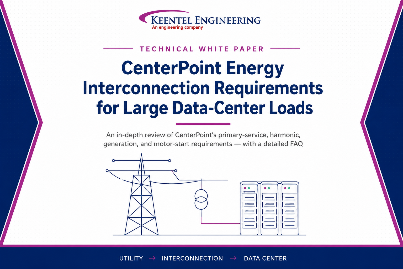
CenterPoint Energy Interconnection
Requirements for Large Data-Center Loads
June 27, 2026 | Blog
1. Executive Summary
CenterPoint Energy (CNP) governs how large electrical loads connect to its distribution system through a set of published specifications. For a large data-center development, four of these documents are central: the specification for MV primary service ,the specification for limitation of harmonic distortion , the specification for customer emergency generation and secondary load transfer , and the Motor Start Review process. Together they define how the service is configured and protected, how harmonic distortion is limited, how backup generation is interconnected, and how large motors are reviewed.
This white paper distills those requirements into a single, project-oriented reference for a large data-center development in the CenterPoint Energy service area. It explains each requirement, highlights the thresholds and rules that most affect a large, electronically-fed data-center load, and closes with a detailed FAQ, a glossary, and a register of the governing documents. The intent is to give a project team a clear, shared understanding of what CenterPoint expects and why — so the engineering, schedule, and budget decisions can be made on a sound basis.
Key takeaway:
A data-center load is large enough to trigger CenterPoint’s service-splitting and circuit-breaker thresholds, and it is dominated by non-linear electronic equipment that makes harmonic compliance (IEEE 519-2014) a real design driver rather than a formality. These two facts shape nearly every requirement discussed below.
2. Purpose & Scope
This document is a technical reference, not a design or a contract. It summarizes and interprets CenterPoint’s published requirements as they apply to a large data-center load and organizes them for quick reference by the project team. Where specific clauses are cited (for example, “Article 4.8.1”), they refer to the corresponding CenterPoint specification listed in Section 13.
The scope covers: the primary-service configuration and protection rules; the harmonic distortion limits and the customer’s modeling and mitigation obligations; the requirements for emergency / backup generation and secondary load transfer; the motor-start review process; the Article 9.0 submittal package required before energization; and CenterPoint’s design-stage process, including how and when the need for a
substation is determined. It does not reproduce the specifications in full, and in any conflict the governing CenterPoint documents and CNP-approved project drawings control.
3. CenterPoint’s Role & the Governing Standards
CenterPoint Energy owns and operates the electric delivery system in its service territory and sets the technical conditions under which a customer may interconnect. CNP reserves the right to refuse to energize any service that fails to meet its specifications or its approved project drawings, and any deviation requires the written approval of CNP’s Manager of Power Quality Engineering or a designated representative. Where a specification and an approved drawing conflict, the drawing governs.
CenterPoint’s requirements sit on top of, and incorporate, broader codes and standards. Customer installations must comply with the National Electrical Code (NEC), the National Electrical Safety Code (NESC) / ANSI-IEEE C2, and local authority requirements. Harmonic control is governed by IEEE 519-2014 and Public Utility Commission of Texas (PUCT) Substantive Rule 25.51. Parallel and closed-transition generation is governed by PUCT Substantive Rules 25.211 and 25.212 and CNP’s customer-generation specification .
| 12 kV and 35 kV Primary Service |
| Limitation of Harmonic Distortion on the Distribution System |
| Customer Emergency Generation and Secondary Load Transfer |
| Review of motors rated 250 HP and larger |
| Customer Generation on the Distribution System |
4. Primary Service Requirements
This specification defines the minimum requirements for primary service at 12,470Y/7,200 V (“12 kV primary service”) and 34,500Y/19,920 V (“35 kV primary service”), both three-phase, four-wire, grounded-neutral. The customer generally furnishes the equipment, and the customer’s first structure on which CNP conductors dead-end is the “Primary Service Pole.”
4.1 Service Voltage & Configuration
Service is provided at 12 kV or 35 kV. For a large load, the higher 35 kV voltage carries less current for the same power and can reduce the number of separate services required. Three-wire utilization equipment is permitted on 12 kV service (bonded to the CNP system neutral) but is not permitted on 35 kV service.
| Requirement | 12 kV Service | 35 kV Serviceme |
|---|---|---|
| Nominal voltage (3Ø, 4-wire, grounded wye) | 12,470Y / 7,200 V | 34,500Y / 19,920 V |
| Overhead equipment BIL (minimum) | 110 kV | 150 kV |
| Underground (pad-mounted) BIL (minimum) | 95 kV | 150 kV |
| Three-wire utilization equipment | Permitted (bonded to neutral) | Not permitted |
4.2 Service Capacity & Service Splitting
Two capacity thresholds are decisive for a large load. First, a service whose connected transformer capacity exceeds 4 MVA at 12 kV or 6 MVA at 35 kV may be required by CNP to be split into two or more separate services, and an Operational Agreement is required when a customer is served from multiple services. Second, the choice between fuses and a circuit breaker as the main
protective device is set by capacity (see Section 4.3). Because these thresholds are far below a data-center-scale load, multiple services, a circuit-breaker main device, and one or more Operational Agreements should be anticipated.
| Threshold | 12 kV | 35 kV | Consequence |
|---|---|---|---|
| Service may be split into multiple services | > 4 MVA | > 6 MVA | Multiple services; Operational Agreement |
| Circuit breaker required (vs. fuses) | > 4,320 kVA | > 11,950 kVA | Breaker / recloser main device |
| Single-phase service limit | 500 kVA | 500 kVA | — |
| Two-phase service limit | 1,000 kVA | 1,000 kVA | Balanced between phases |
4.3 Main Protective Device
Every primary-service customer must provide, install, and maintain a main protective device — either a single group of three fuses or an electronically / electromechanically controlled circuit breaker (hydraulic breakers are not allowed). Fuses may be used only when demand or connected transformer capacity is at or below the thresholds in Section 4.2; above 4,320 kVA at 12 kV or 11,950 kVA at 35 kV, a three-phase circuit breaker (pole-mounted recloser, pad-mounted, or indoor) is required. Important rules for breaker installations include:
- Automatic reclosing is not permitted.
- The customer determines and sets the relay settings, performs functional testing, and provides the settings in an electronic data file plus certified test reports; CNP verifies coordination and loading before energization.
- The breaker control must be accessible to CNP at all times and arranged for both CNP and customer locks.
- A three-phase, gang-operated bypass switch is recommended; if omitted, maintenance outages must be scheduled with CNP under the Operational Agreement.
- Bushing CTs must be on the source side with relay accuracy of C100 or better, and the breaker must have capacitor-trip or battery backup for trip power.
4.4 Disconnecting Device, Overvoltage Protection & BIL
A disconnecting device may be required in addition to the main protective device (for example, when the main device is a pad-mounted breaker). It must be rated for the maximum expected load and fault duty and meet the same BIL minimums as the service. Lightning arresters are recommended on the Primary Service Pole, must be tested to ANSI/IEEE C62.11, and must include a ground-lead isolator; where the main device is pole-mounted, arresters connect on its load side.
4.5 Transformer Connection Rules
Two winding-connection restrictions apply to the customer’s medium-voltage system and must be reflected in the one-line and transformer selections:
- Grounded-wye primary to delta secondary transformers shall not be used on the customer’s 12 kV or 35 kV distribution system.
- Transformers with ungrounded primary connections (delta or ungrounded wye) shall not be used on the customer’s 35 kV distribution system.
4.6 Capacitor Banks
A customer wishing to install a 12 kV or 35 kV capacitor bank must submit a description of the bank and its control to CNP, and CNP may require load- or power-factor-sensitive switching. Customers with harmonic-producing loads may be required to install harmonic filters in accordance with the harmonic specification . Because capacitors can create resonance with harmonic sources, capacitor application on a data-center system must be coordinated with the harmonic evaluation.
4.7 Overhead vs. Underground Primary Service
Overhead service centers on the customer’s Primary Service Pole, which must be designed for CNP’s adopted extreme-wind loading (110 mph north of US 59 / Hwy 90, 132 mph south of US 59 / Hwy 90) and located a minimum of 50 feet from the CNP metering pole with all-weather truck access.
Underground service is handled by CNP’s Major Underground Engineering group, may be served from outdoor (pad-mounted) or indoor facilities, and is delivered with a project-specific Terms & Conditions package; cable from the metering cabinet or vault must be in concrete-encased conduit (direct burial is not permitted). For a large campus, the design stage typically develops a primary overhead route into the site with major underground utilities on site connecting to the overhead system.
5. Harmonic Distortion Control (Spec 083, Rev. 3)
This specification places responsibility for limiting harmonic flow into the CNP system on the customer and reflects IEEE 519-2014 and PUCT Rule 25.51. CNP may refuse to energize a non-compliant service and may measure the customer’s harmonic injection at the point of common coupling (PCC) at any time. Measurement instruments follow IEC 61000-4-7 and IEC 61000-4-30.
5.1 Why It Matters for a Data Center
A data center is dominated by non-linear electronic loads — UPS rectifiers, switch-mode power supplies, and variable-frequency-drive cooling — that draw current in a non-sinusoidal manner. CenterPoint notes that electronic power converters typically create current distortion on the order of 20–30% of rating for three-phase equipment. Left unmanaged, that distortion can exceed CNP’s limits, disrupt other customers, and prevent energization. Harmonic compliance is therefore a substantive design task, not a check-the-box item.
5.2 Current Distortion Limits (Iₛₜ/Iₗ and TDD)
Allowable harmonic current injection is expressed as a percentage of the maximum demand load current (Iₗ), and the allowance grows as the short-circuit-to-load ratio (Iₛₜ/Iₗ) at the PCC grows. The table below reproduces CNP’s current distortion limits (from IEEE 519-2014, Table 2). Even-order harmonics are limited to 25% of the odd-order limits, and — importantly for backup generation — all power-generation equipment is held to the most stringent (“< 20”) row regardless of the actual Iₛₜ/Iₗ. Distortions that produce a DC offset (e.g., half-wave converters) are not allowed.
| Iₛₜ / Iₗ | 3≤h<11 | 11≤h<17 | 17≤h<23 | 23≤h<35 | 35≤h<50 | TDD |
|---|---|---|---|---|---|---|
| < 20 | 4.0 | 2.0 | 1.5 | 0.6 | 0.3 | 5.0 |
| 20 – 50 | 7.0 | 3.5 | 2.5 | 1.0 | 0.5 | 8.0 |
| 50 – 100 | 10.0 | 4.5 | 4.0 | 1.5 | 0.7 | 12.0 |
| 100 – 1000 | 12.0 | 5.5 | 5.0 | 2.0 | 1.0 | 15.0 |
| > 1000 | 15.0 | 7.0 | 6.0 | 2.5 | 1.4 | 20.0 |
Values are percent of maximum demand load current Iₗ. Limits apply to odd harmonics; even harmonics are limited to 25% of the values shown. TDD = Total Demand Distortion.
5.3 Voltage Distortion Limits
IEEE 519 also defines voltage-distortion limits at the PCC, which filter and mitigation designs must respect:
| Bus voltage at PCC | Individual harmonic limit | Total harmonic distortion (THD) limit |
|---|---|---|
| V ≤ 1.0 kV | 5.0% | 8.0% |
| 1 kV < V ≤ 69 kV | 3.0% | 5.0% |
5.4 Modeling, Measurement & Mitigation
CenterPoint requires the customer to model its system to project harmonic levels and to determine whether limits will be exceeded. Supporting data the customer must provide includes a one-line showing ratings and connections, capacitor data, conductor sizes and impedances, the location and type of non-linear loads, the overall plant load and the non-linear portion, and transformer ratings, connections, and impedances. On written request, CNP supplies system data such as available fault duty, system impedance, and transformer ratings. If limits would be exceeded, the customer is responsible for designing, installing, and maintaining mitigation — current-limiting reactors, passive traps and filters, or active conditioners — subject to approval by CNP’s Manager of Power Quality. Mitigation should be designed to operate independently of the CNP supply characteristics, because CNP reconfigures its system over time.
6. Emergency Generation & Secondary Load Transfer (Spec 082, Rev. 1)
6.1 Emergency / Backup Generation
Customer-owned emergency generation must connect to the customer’s load through either an open-transition transfer switch or a key-interlocked two-breaker / switch arrangement that prevents any electrical or physical connection between the CNP system and the customer’s generator bus. Standby generators must sit on the load side of the meter, behind the main device; no transfer switch is allowed on the high (CNP) side of the meter. The generator and its exhaust must be located where they do not interfere with CNP personnel or equipment, and the location must be approved by CNP.
Operating a generator in parallel with the CNP system (closed transition) is an exception that is granted only when the customer installs protective devices in accordance with PUCT Substantive Rule 25.212 and CNP’s customer-generation specification (007-231-76) at the interconnection point, and when generator voltage and current distortion comply with IEEE 519. Customers served from a CNP secondary network may not parallel generators with CNP at all. Recall also that, under the harmonic specification, generation equipment is held to the most stringent harmonic-distortion category.
6.2 Secondary Load Transfer
Where a customer’s split load is served from two CNP feeds, the buses from each feed must be electrically isolated from one another, and load transfers must be performed manually using open-transition transfer switches or breakers — automatic transfer by the customer is not permitted without CNP Engineering approval. Before transferring, the customer must shed an equal or greater amount of pre-approved load on the receiving feed so the normal load level is never exceeded. Secondary load transfer is offered only under separate contractual arrangements, requires submission of a load-transfer schedule, and is documented in an Operational Agreement.
7. Motor Starting Review
Any motor rated 250 HP or larger must be reviewed by CNP’s power-quality engineer using the Motor Start Review Form. The form captures service information (service name and address, circuit and section, transformer GLN, service voltage, transformer type), present and future kVA demand, and — for each motor or motor group — a data table including the number of motors, horsepower, phase, voltage, full-load amps, locked-rotor amps, code letter (locked-rotor kVA per HP), required starting frequency, whether the motor starts under load, and the starting method. Recognized starting methods are full-voltage / across-the-line (FVS), auto-transformer reduced-voltage (ATRF), capacitor start (CAPS), star-start delta-run (SSDR), and other (OTHR). Where motors start simultaneously, a description of the scheme must be attached. For a
data center, large chillers and pumps are the most likely candidates to trigger this review.
8. The Article 9.0 Submittal Package
Before any construction to serve the customer may begin, CenterPoint requires a submittal package to be reviewed and approved. CNP typically identifies the following items (per Article 9.0 and project-specific guidance):
| Submittal Item | Applies When |
|---|---|
| Basic primary one-line showing the main protective device and all primary-connected transformers (kVA + winding configurations) | Always |
| All electrical equipment downstream of the CNP interconnection | Always |
| Load analysis listing conventional loads and harmonic-producing loads (kVA), with harmonic-compliance documentation (per 083) | Always |
| Detail of harmonic-producing loads | Always |
| Customer plot plan of property and facilities | Always |
| Primary service pole profile with main protective device and clearances | Overhead service |
| Major equipment data (manufacturer, catalog, specs) — service pole / underground arrangement | Always |
| Capacitor bank information (Article 8.0) | If capacitors used |
| Motor starting information — motors ≥ 250 HP (Motor Start Review Form) | If applicable |
| Emergency backup generator information (per 082) | If generators used |
For a service with a circuit-breaker main device, CNP additionally expects relay and equipment bills of material, breaker / recloser schematics, and the electronic setting file with time-current-curve (TCC) coordination data. All required submittals must be approved before construction begins.
9. The Design-Stage Process & the Substation Question
CenterPoint has advised that the design stage is approximately a three-to-six-month process. During this stage, CNP develops the primary overhead design into the site and the major underground utilities on site that connect to the overhead system. Critically, if a substation is required to serve the load, that requirement is identified during this stage. In parallel, CNP’s power-quality engineer reviews and approves the customer’s major equipment and prepares the Operational Agreement. Only after these steps are complete does CNP finalize its construction costs; payment then allows construction to commence.
Because a data-center-scale load sits well above the single-service thresholds, the central engineering question of the design stage is whether the load can be served from existing infrastructure through multiple primary services or whether dedicated substation infrastructure is the controlling path. Producing a defensible answer early — grounded in the load analysis, service-voltage selection, and CNP’s feedback — is one of the most valuable outcomes of this phase.
Operational Agreement triggers. An Operational Agreement is required when the customer uses a circuit breaker as the main protective device, does not install a bypass switch on the Primary Service Pole, operates generation in parallel with CNP, or receives service from two CNP feeds with the ability to transfer load. A large data-center service is likely to trigger more than one of these.
10. What This Means for a Large Data-Center Project
Bringing the requirements together, several implications follow directly for a large data-center load in the CenterPoint service area:
- Service configuration: at roughly an order of magnitude above the single-service splitting thresholds, the facility should anticipate multiple primary services and/or dedicated substation infrastructure; 35 kV service merits evaluation to reduce current and service count.
- Protection: a circuit-breaker main device (not fuses) will be required, with customer-set, CNP-verified relay coordination, no automatic reclosing, and one or more Operational Agreements.
- Harmonics: the UPS / rectifier / VFD load makes IEEE 519 compliance a real design driver; a harmonic model and, likely, a mitigation strategy will be needed, and any capacitors must be coordinated to avoid resonance.
- Transformers: winding connections must respect the prohibitions (no grounded-wye / delta on the customer system; no ungrounded primary at 35 kV).
- Backup generation: open-transition or key-interlocked connection on the load side of the meter, with the stricter generation harmonic category, and additional protection if parallel operation is ever desired.
- Large motors: chillers or pumps rated 250 HP and larger will trigger the Motor Start Review.
- Process: the substation determination, equipment approval, and Operational Agreement are CNP-controlled and occur over the three-to-six-month design stage before final costs are set.
Large data-center programs are frequently advanced in phases — for example, an initial build served at the distribution-primary level through CenterPoint’s design process described here, and a larger build that crosses into transmission-level service and the ERCOT large-load study process. The requirements in this paper apply principally to the distribution-level work; a transmission-level interconnection introduces additional ERCOT modeling deliverables (load data, dynamic, and PSCAD / EMT models) that are addressed separately.
11. Frequently Asked Questions
Q. Will CenterPoint serve the facility at 12 kV or 35 kV?
Either is possible; CNP makes the determination during design. For a large load, 35 kV (34,500Y/19,920 V) is often advantageous because it carries less current for the same power and can reduce the number of separate services. The trade-offs (equipment cost, BIL, available infrastructure) are evaluated in the conceptual architecture and confirmed with CNP.
Q. Why might our load require multiple services or a substation?
CenterPoint’s specification allows it to require a service to be split into two or more services when connected transformer capacity exceeds 4 MVA at 12 kV or 6 MVA at 35 kV. A data-center-scale load is far above that, so multiple services and/or dedicated substation infrastructure should be anticipated. Whether a substation is required is determined by CNP during the design stage.
Q. When is a circuit breaker required instead of fuses?
When demand or connected transformer capacity exceeds 4,320 kVA at 12 kV or 11,950 kVA at 35 kV, a three-phase circuit breaker (recloser, pad-mounted, or indoor) is required. A data-center load is well above these thresholds, so a breaker main device is expected.
Q. What is an Operational Agreement and when do we need one?
It is a signed agreement between CNP and the customer that governs operating procedures (for example, what happens when the main breaker trips, or how maintenance outages are scheduled). It is required when a circuit breaker is the main device, when no bypass switch is installed, when generation operates in parallel with CNP, or when service comes from two feeds with load-transfer capability. A large service is likely to trigger more than one of these.
Q. What transformer connections are prohibited?
Grounded-wye primary to delta secondary transformers may not be used on the customer’s 12 kV or 35 kV system, and transformers with ungrounded primaries (delta or ungrounded wye) may not be used on the customer’s 35 kV system. Transformer selections and the one-line must reflect these rules.
Q. Why is the harmonic evaluation so important for a data center?
Data-center loads are dominated by non-linear electronics (UPS rectifiers, switch-mode supplies, VFD cooling) that inject harmonic current. CenterPoint makes the customer responsible for limiting that injection to IEEE 519-2014 limits and can refuse to energize a non-compliant service. The evaluation determines whether limits are met and what mitigation, if any, is required.
Q. How are the IEEE 519 current limits determined?
Limits are a percentage of the maximum demand load current (Iₗ) and depend on the short-circuit-to-load ratio (Iₛₜ/Iₗ) at the point of common coupling — a higher ratio allows higher percentages. Iₛₜ comes from CNP system data; Iₗ is the facility’s maximum demand current (estimated for a new load). The applicable row of the limits table (Section 5.2) then sets the individual-harmonic and Total Demand Distortion (TDD) limits.
Q. What harmonic limit applies to our backup generators?
All power-generation equipment is held to the most stringent “< 20” category of the current-distortion table regardless of the actual Iₛₜ/Iₗ ratio. Generators must therefore meet tighter limits than the rest of the facility.
Q. How must backup generators be connected?
Through an open-transition transfer switch or a key-interlocked two-breaker / switch arrangement that prevents any connection between the CNP system and the generator bus. Generators sit on the load side of the meter, behind the main device; no transfer switch is allowed on the CNP side of the meter.
Q. Can we run generators in parallel with CenterPoint?
Only as an exception, and only if protective devices meeting PUCT Rule 25.212 and CNP’s generation specification are installed at the interconnection point and IEEE 519 distortion limits are met. Customers on a CNP secondary network may not parallel at all.
Q. When does the Motor Start Review apply?
Any motor rated 250 HP or larger must be reviewed by CNP’s power-quality engineer using the Motor Start Review Form, which captures motor data (HP, full-load and locked-rotor amps, code letter, starting method, etc.). For a data center, large chillers and pumps are the usual candidates. Simultaneous starts require a description of the scheme.
Q. What must we submit before construction can begin?
The Article 9.0 package (Section 8): a primary one-line with transformers and the main device, downstream equipment, a load analysis separating conventional and harmonic-producing loads with harmonic-compliance documentation, a plot plan, service-pole profile, equipment data, and — if applicable — capacitor, motor-start, and generator information. Breaker services also require relay data, schematics, and setting files / TCC curves. Everything must be approved before construction.
Q. How long does the design stage take?
CenterPoint describes it as approximately a three-to-six-month process, covering primary overhead design into the site and the major on-site underground utilities, equipment approval by the power-quality engineer, and preparation of the Operational Agreement. The duration is controlled by CNP.
Q. When will we know whether a substation is required?
CenterPoint advises that the need for a substation, if any, is identified during the design stage. Keentel’s engineering develops the technical basis (load, service voltage, service count) to inform that determination as early as possible, but the decision rests with CNP.
Q. Who approves our equipment, and how?
CNP’s Manager / engineer of Power Quality reviews and approves the customer’s major electrical equipment as part of the design stage, based on the Article 9.0 submittals. Any deviation from the specification requires that office’s written approval.
Q. What testing does CenterPoint require before energization?
After approval and construction, CNP inspects the work. For a recloser / breaker main device, the customer performs a witness test with secondary current injection — demonstrating a line-to-ground fault and a three-phase fault at minimum pickup, each tripping with no reclose — and verifies the previously approved settings. Service is not energized until it passes inspection and all requirements are complete.
Q. What is the difference between overhead and underground service?
Overhead service uses a customer Primary Service Pole designed for CNP’s extreme-wind loading and located at least 50 feet from the CNP meter pole with truck access. Underground service is handled by CNP’s Major Underground Engineering group, may be outdoor or indoor, comes with a Terms & Conditions package, and requires cable in concrete-encased conduit (no direct burial).
Q. Who is responsible if harmonic limits are exceeded?
The customer. CenterPoint requires the customer to model the system, and to design, install, and maintain any mitigation (reactors, filters, active conditioners) needed to meet IEEE 519, subject to CNP power-quality approval. CNP may also measure harmonic injection at the meter at any time after energization.
Q. How does distribution-level service relate to a transmission-level study?
Smaller / initial builds are often served at the distribution-primary level through CenterPoint’s design process described in this paper. A sufficiently large load crosses into transmission-level service and is handled through the ERCOT large-load study process, which adds modeling deliverables (Load Data Request Form, dynamic load model, and a PSCAD / EMT model) for ERCOT and CenterPoint planning review. The two tracks are complementary and are typically scoped and proposed separately.
Q. What happens if our installation doesn’t meet the specification?
CenterPoint reserves the right to refuse to energize any service that fails to meet its specifications or approved drawings. Deviations require written approval from CNP’s Manager of Power Quality. The practical implication is that aligning the design to these requirements up front avoids re-work and schedule loss.

About the Author:
Sandip "Sonny" R. Patel, P.E.
IEEE Senior Member · Founder & CEO, Keentel Engineering
In 1995, Sonny Patel earned his Electrical Engineering degree from the University of Illinois. But degrees don't build legacies — action does.
For three decades, he has worked the power industry from every side of the table: 16 years as a utility engineer at Exelon/Commonwealth Edison; generation leadership across hydroelectric, industrial steam turbine, and a 9 GW renewable fleet; NERC Regional Entity Senior Compliance Engineer and Audit Team Lead, auditing some of the nation's largest utilities; and testing and commissioning lead on equipment up to 765 kV — the very top of the North American grid.Utility. Generator. Regulator. Consultant. Few engineers have seen all four seats. Fewer still have sat in them.
His experience spans nuclear, hydro, conventional generation, renewables, oil and gas, mining — and today's data centers, where he is authoring a three-book series on data center design. He is a Licensed Professional Engineer in six states and a Licensed Electrical Contractor in Florida (Unlimited EC) — he doesn't just design the work; he's qualified to stand behind its execution.Today, as Founder and CEO of Keentel Engineering, Sonny leads a nationwide team of engineers delivering substation design, power system studies, NERC compliance, and commissioning — done right, coast to coast.Three decades. Every side of the table. One standard: accountable engineering.
Services

Let's Discuss Your Project
Let's book a call to discuss your electrical engineering project that we can help you with.
About the Author:
Sandip "Sonny" R. Patel, P.E.
IEEE Senior Member · Founder & CEO, Keentel Engineering
In 1995, Sonny Patel earned his Electrical Engineering degree from the University of Illinois. But degrees don't build legacies — action does.
For three decades, he has worked the power industry from every side of the table: 16 years as a utility engineer at Exelon/Commonwealth Edison; generation leadership across hydroelectric, industrial steam turbine, and a 9 GW renewable fleet; NERC Regional Entity Senior Compliance Engineer and Audit Team Lead, auditing some of the nation's largest utilities; and testing and commissioning lead on equipment up to 765 kV — the very top of the North American grid.
Utility. Generator. Regulator. Consultant. Few engineers have seen all four seats. Fewer still have sat in them.
His experience spans nuclear, hydro, conventional generation, renewables, oil and gas, mining — and today's data centers, where he is authoring a three-book series on data center design. He is a Licensed Professional Engineer in six states and a Licensed Electrical Contractor in Florida (Unlimited EC) — he doesn't just design the work; he's qualified to stand behind its execution.
Today, as Founder and CEO of Keentel Engineering, Sonny leads a nationwide team of engineers delivering substation design, power system studies, NERC compliance, and commissioning — done right, coast to coast.Three decades. Every side of the table. One standard: accountable engineering.
Leave a Comment
Thank you for contacting us.
We will get back to you as soon as possible.
We will get back to you as soon as possible.
Oops, there was an error sending your message.
Please try again later.
Please try again later.
Related Posts

By SANDIP R PATEL
•
October 11, 2026
Explore grid inertia, RoCoF and frequency response, with swing equation calculations, frequency nadir analysis and US power system simulation examples.

By SANDIP R PATEL
•
October 11, 2026
Learn how STATCOMs improve voltage stability and prevent FIDVR. Explore reactive power sizing, delayed fault clearing, NERC criteria and 138 kV simulation results.

By SANDIP R PATEL
•
October 10, 2026
Learn BESS DC sizing with power, energy, current and C-rate calculations, battery losses, degradation and a 100 MW/400 MWh utility-scale example.

By SANDIP R PATEL
•
October 10, 2026
Learn how BESS ROI is calculated using peak shaving, energy arbitrage, power quality and battery storage economics, with a practical 5 MW/10 MWh example.
By SANDIP R PATEL
•
October 10, 2026
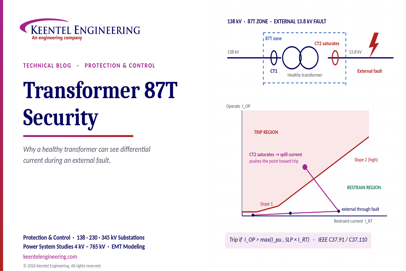
Learn why transformer differential relays detect current during external faults, how CT saturation causes spill current, and how secure 87T protection prevents trips.
By SANDIP R PATEL
•
October 10, 2026
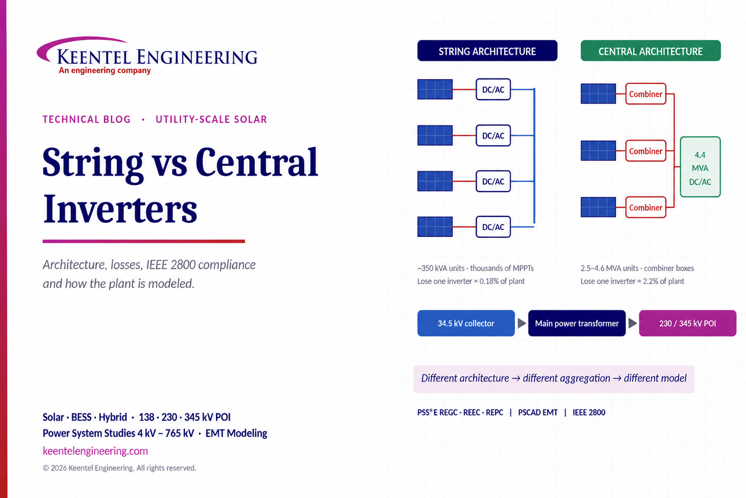
Compare string vs central inverters for utility-scale solar, including efficiency, maintenance, grid compliance, reactive power and interconnection studies.
By SANDIP R PATEL
•
October 9, 2026
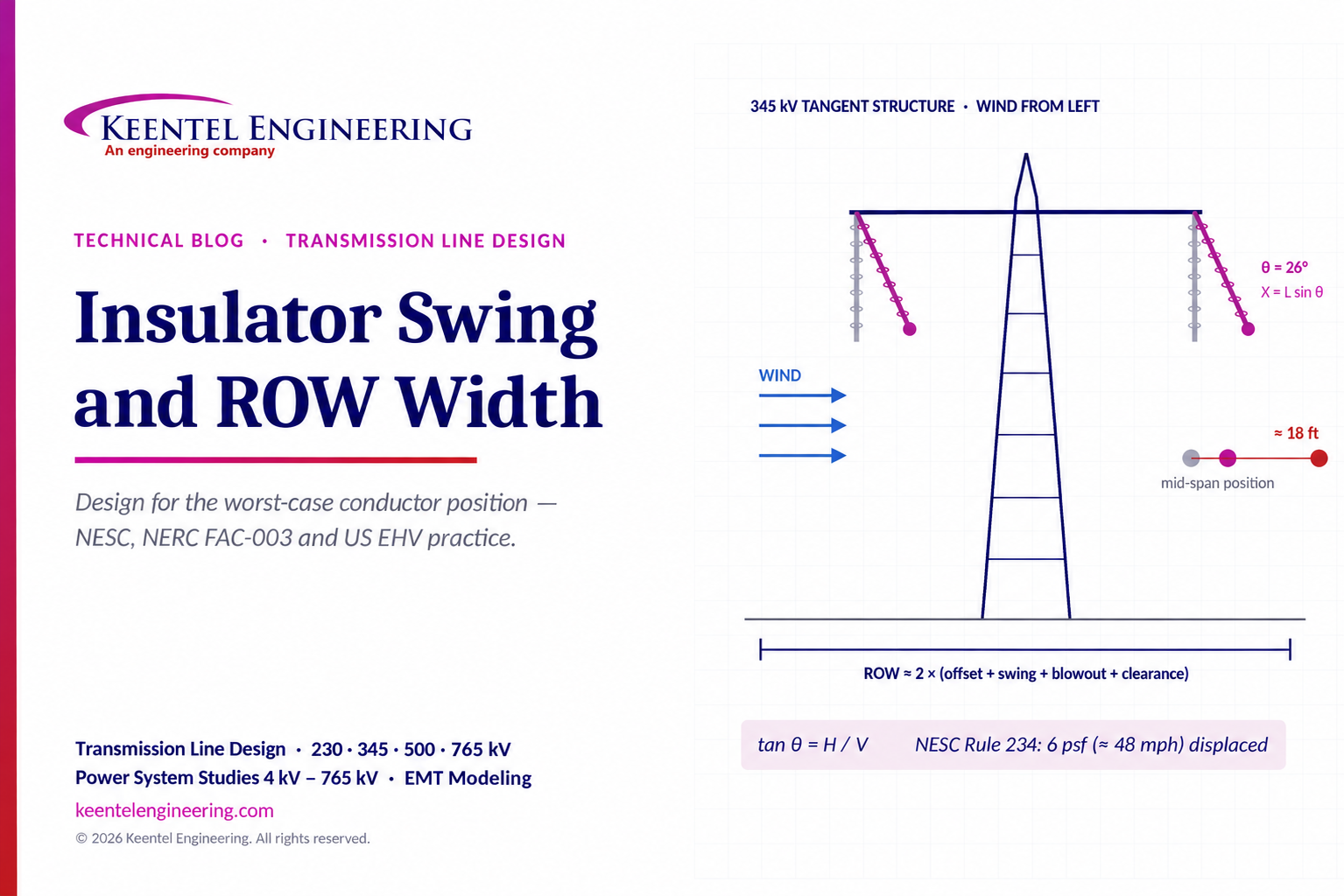
Learn how insulator swing angle and conductor blowout affect transmission line ROW width, with NESC clearances, NERC FAC-003 guidance, and a 345 kV example.
Copy

By SANDIP R PATEL
•
October 3, 2026
Engineering guide to PRC-028 disturbance recording, PRC-029 ride-through and PRC-030 event detection for inverter-based resources.

By SANDIP R PATEL
•
October 3, 2026
A practical guide to SSO classification, SSR, PEDI, Wind-SSCI, EMT analysis, mitigation and protection based on CIGRE TB 909.





