A Coordinated Electric System Interconnection Review—the utility’s deep-dive on technical and cost impacts of your project.
Challenge: Frequent false tripping using conventional electromechanical relays
Solution: SEL-487E integration with multi-terminal differential protection and dynamic inrush restraint
Result: 90% reduction in false trips, saving over $250,000 in downtime
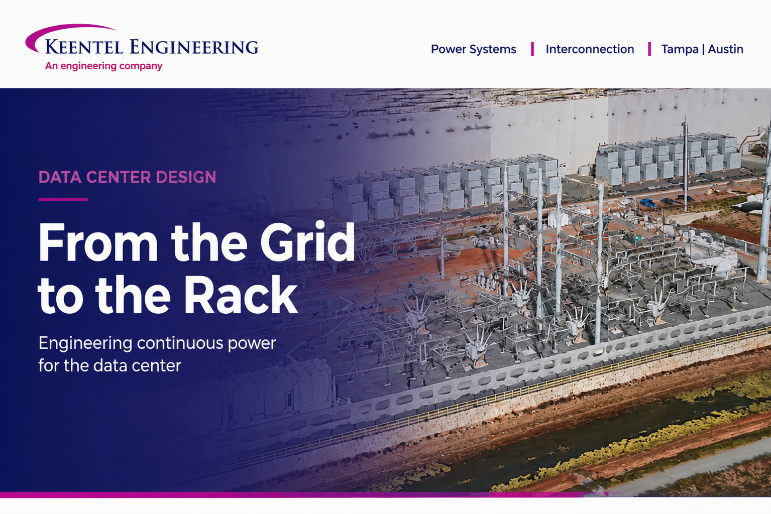
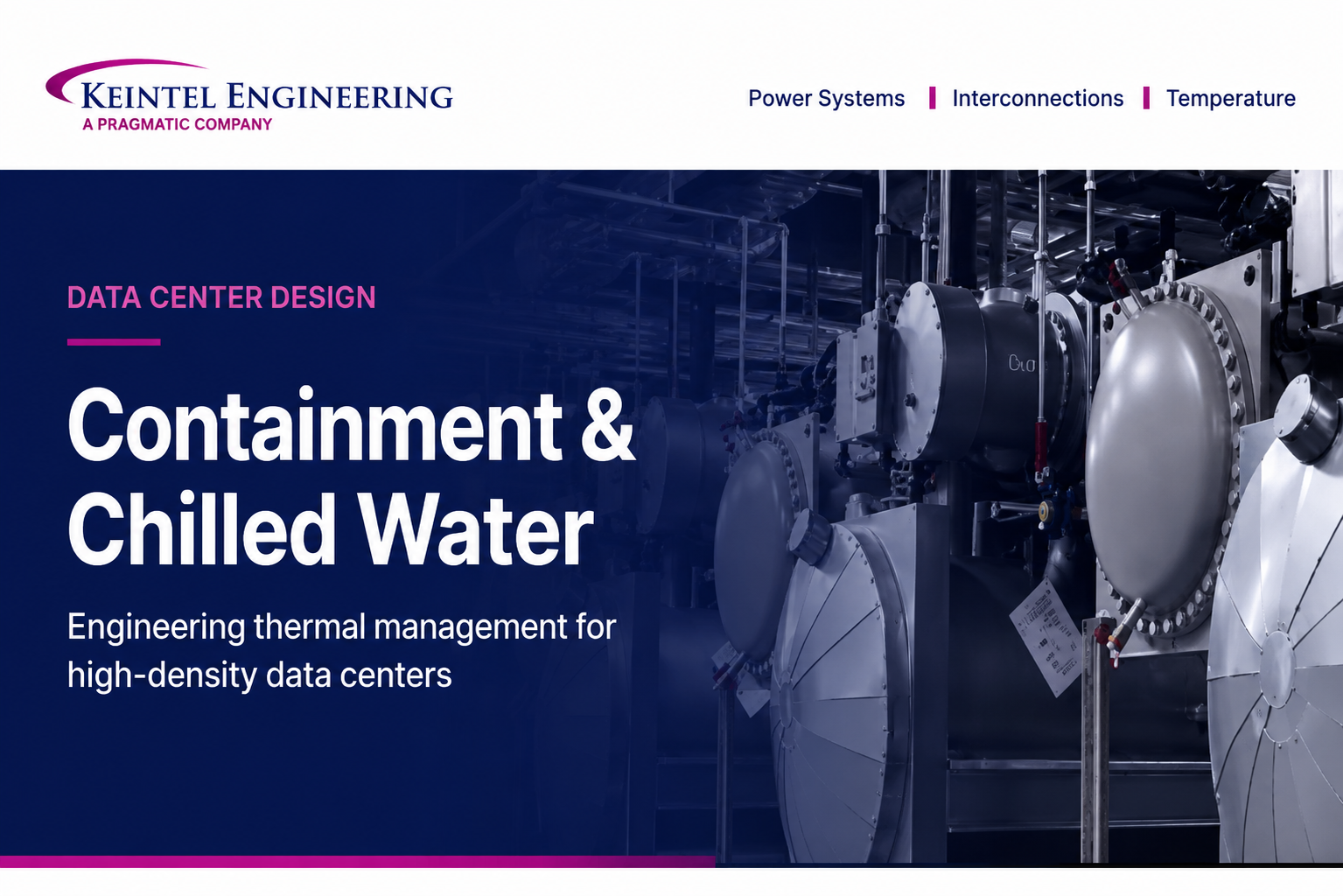
Containment and Chilled Water: Engineering Thermal Management for High-Density Data Centers
Jun 18, 2026 | Blog
How airflow containment and chilled water systems work together to remove heat, protect uptime, and shape the electrical load a facility ultimately draws from the grid.
Why Thermal Management Is a First-Order Design Decision
In a data center, the servers are the reason the building exists, and the electrical system is what keeps them running. But neither matters if the heat those servers produce cannot be removed continuously. Every watt of power delivered to IT equipment is converted, almost entirely, into heat that must be carried back out of the building every second of every day. A facility can have flawless power infrastructure and still fail within minutes if its cooling stops.
That makes thermal management a first-order engineering problem rather than a secondary mechanical detail. It directly governs reliability, the temperatures equipment is held at, the energy a site consumes for non-computing functions, and ultimately the total electrical load presented at the point of interconnection. Two design domains carry most of that responsibility: airflow management inside the data hall, and the chilled water system that removes the heat the air picks up. This guide treats them as the connected system they are.
The Keentel lens
Cooling is not just a mechanical line item. The cooling plant is one of the largest electrical loads in the building. Decisions about containment, supply temperatures, and heat-rejection method change a facility's effective load profile and its total interconnection request, which is where power systems engineering and mechanical design meet.
The Core Problem: Heat, Airflow, and the Cost of Mixing
Most server-class equipment is front-to-back air cooled. Cold air is drawn in through the front intake, passed across heat-generating components, and exhausted out the rear at a substantially higher temperature. The cooling system's job, at its simplest, is to deliver cold air to those intakes and collect the hot exhaust for heat rejection.
The single most damaging inefficiency in this loop is the mixing of hot exhaust air with the cold supply air before it reaches the servers. When the two streams blend, the air arriving at the intakes is warmer than intended, so the cooling plant must overcool the supply to compensate. The consequences compound quickly:
- Higher energy consumption, because the plant works harder and runs colder than it needs to.
- Localized hot spots, where recirculated exhaust raises inlet temperatures above equipment limits and triggers throttling or thermal shutdown.
- Reduced usable cooling capacity, since a meaningful fraction of the cold air never does useful work.
- Greater strain and shortened service life on cooling units forced to operate outside their efficient range.
There are two failure modes worth naming precisely. Recirculation is hot exhaust looping back to an intake. Bypass is cold supply air returning to the cooling unit without ever passing through a server. Both waste capacity, and both are symptoms of the same root issue: the hot and cold air are sharing the same volume. Every airflow strategy that follows is fundamentally an effort to keep those two streams apart.
Rack Layout Fundamentals: The Hot-Aisle / Cold-Aisle Arrangement
The baseline discipline that makes everything else possible is orienting racks into alternating hot and cold aisles. Rows are arranged so that rack fronts face each other across one corridor and rack backs face each other across the next.
Cold-aisle orientation
The corridor between two rows of rack fronts becomes the cold aisle. Conditioned air is delivered into it, classically through perforated tiles in a raised floor or through overhead ducting, and the servers draw it in. This organizes supply air where the intakes are, rather than dumping it into the room at large.
Hot-aisle orientation
Behind the racks, the backs face each other into the hot aisle, which concentrates exhaust into a defined corridor that can be directed back toward the cooling units. Collecting the hot air in one place raises the return air temperature, and a warmer, more concentrated return stream is precisely what makes cooling equipment more efficient.
This alternating layout is a major improvement over a randomly arranged room, but on its own it is incomplete. With nothing sealing the aisles, hot and cold air still mix freely over the tops of the racks and around the ends of the rows. The layout sets the stage; containment closes the gaps.
Containment: Sealing the Boundary Between Hot and Cold
Containment takes the hot-aisle/cold-aisle arrangement and physically encloses one of the two aisles so the streams cannot mix at all. The enclosure is built from ceiling panels or vertical baffles above the racks, doors at the ends of the rows, and blanking panels that seal the open rack units and gaps between cabinets. The principle is simple: give the cold air exactly one path, from supply to intake to exhaust to return, with no shortcuts. Two strategies dominate.
Cold-Aisle Containment
Here the cold aisle is enclosed. Supply air is trapped in the sealed corridor in front of the racks, so every server sees consistent, low-temperature intake air. The hot exhaust is allowed to fill the rest of the room, which becomes a large warm-air return plenum.
Strengths: It is generally the simpler and lower-cost approach, especially as a retrofit to an existing raised-floor hall. It delivers tightly controlled, uniform inlet temperatures, which is exactly what equipment warranties care about.
Trade-offs: The general room volume runs warm, which can be uncomfortable for staff and harder on equipment located outside the contained aisle, such as network gear and power distribution. The approach also tends to lose its efficiency edge at very high rack densities, where the volume of hot air the room must absorb becomes difficult to manage.
Hot-Aisle Containment
Here the hot aisle is enclosed instead. Exhaust is captured immediately and ducted, often through an overhead return plenum, straight back to the cooling units. The rest of the room is flooded with cool supply air and becomes the comfortable, equipment-friendly space.
Strengths: It typically achieves higher overall efficiency and performs better in high-density environments. Because the return air is captured hot and undiluted, the cooling coils see a larger temperature difference and the plant can run warmer supply temperatures, which unlocks economization (discussed below). The bulk of the room stays cool, which is easier on ancillary equipment and personnel.
Trade-offs: Design and installation are more involved, upfront cost is higher, and the enclosed hot aisle must be coordinated carefully with fire detection and suppression because the ceiling plane and ducting change how smoke and suppression agents move.
The distinction in intent is worth stating plainly. Cold-aisle containment is organized around protecting the equipment by guaranteeing a consistent intake temperature. Hot-aisle containment is organized around maximizing plant efficiency by managing the return air. In modern high-density and AI-oriented builds, hot-aisle containment is generally the preferred strategy, because control of return-air temperature is what makes the rest of the cooling system efficient at scale.
Side-by-side comparison
| Attribute | Cold-Aisle Containment | Hot-Aisle Containment |
|---|---|---|
| What is enclosed | The cold supply aisle (rack fronts) | The hot exhaust aisle (rack backs) |
| Room condition | The cold supply aisle (rack fronts) | Room runs cool; hot air is ducted away |
| Primary objective | Consistent equipment inlet temperature | Efficient return-air management |
| Efficiency at high density | Falls off as density rises | Strong; scales well |
| Upfront cost & complexity | Lower; simpler retrofit | Higher; more design coordination |
| Fire / life-safety | Fewer complications | Requires careful suppression coordination |
| Best fit | Retrofits, moderate density | New high-density and AI-class builds |
Tuning the Air Side: Temperature Envelopes and Economization
Containment is what makes aggressive temperature strategies safe. Once hot and cold streams are separated, the operator can run warmer than the cautious, overcooled set points of a mixed room without risking equipment.
Industry thermal guidance, most commonly the ASHRAE TC 9.9 recommendations, defines a recommended inlet-air envelope of roughly 18 to 27 degrees Celsius (about 64 to 81 degrees Fahrenheit), with wider allowable ranges for short excursions. Many operators historically ran far colder than necessary out of caution. Effective containment lets them move set points up toward the warmer end of the recommended band with confidence, and warmer supply air is cheaper to produce.
The larger prize is economization, or free cooling. When the system can supply acceptably warm air, the chilled water plant can lean on outdoor conditions to reject heat for large parts of the year, reducing or eliminating mechanical refrigeration during cool weather. A waterside economizer uses the cooling towers to make chilled water directly when ambient wet-bulb temperature is low enough; an airside economizer brings in filtered outside air. Either way, the savings only materialize because containment allows the warmer operating temperatures that make outdoor conditions useful. Containment, supply temperature, and economization are a single linked decision, not three separate ones.
Behind the Air: The Chilled Water System
Air moves heat around inside the hall, but it does not remove heat from the building. That work is done by a mechanical system, and at scale that system is almost always a chilled water plant. Conceptually it is straightforward: water is an excellent, dense heat-transport medium, and the plant uses it to carry heat from the data hall to the outdoors and dump it there.
The loop step by step
- A chiller produces cold water.
- Pumps push that chilled water out to the data hall.
- Inside the hall, the water flows through coils in air-handling units; room air passes over the coils and is cooled.
- The cooled air is delivered to the server intakes through the contained cold aisle.
- Servers absorb the cool air and exhaust it hot.
- The hot return air passes back over the coils, transferring its heat into the water.
- The now-warm water returns to the chiller.
- The chiller rejects that heat to the outside environment, and the cycle repeats continuously.
The temperature difference between supply and return water, the system delta-T, is a key efficiency metric: a larger delta-T means each gallon of water carries more heat, so the plant can move a given load with less pumping energy. Much of chilled water design is, in effect, the pursuit of a healthy delta-T, and good containment supports it by keeping return air hot and undiluted.
Major Components
Chillers
Chillers are the heart of the plant. They use a refrigeration cycle, conceptually a very large air conditioner, to pull heat out of the water. They come in two broad families that differ in how they reject heat.
- Air-cooled chillers reject heat directly to the outdoor air, typically through integral condenser coils and fans. They are simpler, use little or no water, and suit smaller plants or water-constrained sites, but they are generally less efficient and lose capacity in hot weather.
- Water-cooled chillers reject heat to a condenser-water loop served by cooling towers. They are more efficient and scale better for large facilities, at the cost of a more complex plant and significant water consumption.
Cooling towers
In a water-cooled plant, cooling towers reject the system's heat by evaporating a portion of the condenser water, one of the most effective large-scale heat-rejection mechanisms available. Their performance tracks the outdoor wet-bulb temperature rather than the dry-bulb, which is why they remain effective even in warm climates and why they enable waterside economization. The trade-off is water: evaporative rejection consumes water continuously, which is why water-use effectiveness has become a sustainability metric alongside energy.
Pumps
Pumps keep water moving through the loops. Plants commonly separate primary pumps, which circulate water through the chillers at a stable flow, from secondary pumps, which deliver water out to the building loads and vary their flow to match demand. This separation protects the chillers from flow swings while letting the distribution side modulate efficiently.
Air-handling units in the hall
Inside the data hall, computer room air handlers (CRAH units) contain the chilled water coils. Hot return air from the contained aisle passes over the coils, gives up its heat to the water, and the cooled air is supplied back to the cold aisle. CRAH units rely on the central chilled water plant rather than housing their own refrigeration, which is the defining difference between a chilled water approach and a direct-expansion one. The air side and the water side meet at this coil, which is exactly why containment and chilled water design have to be considered together.
Why Chilled Water Beats Direct Expansion at Scale
A reasonable question is why large facilities go to the trouble of a chilled water plant instead of distributed direct-expansion (DX) units, such as packaged rooftop systems, which are simpler per unit. At small scale DX is often the right answer. At data center scale the balance reverses:
- Efficiency. Centralized chillers and evaporative heat rejection are markedly more efficient per unit of heat removed than many small DX compressors.
- High heat loads. Water carries far more heat per unit volume than air, making it better suited to the megawatt-scale loads modern halls produce.
- Centralized control. One plant is easier to monitor, optimize, and stage than dozens of independent units.
- Flexible redundancy. It is far easier to build N+1 or 2N reliability into a centralized plant with shared spares than to duplicate every distributed unit.
For these reasons most large facilities rely on chilled water rather than packaged DX, reserving DX for smaller spaces or specific edge applications.
Designing for Reliability: Redundancy and Concurrent Maintainability
Cooling in a data center is designed with the same uncompromising reliability philosophy as the electrical system, because the two share the same intolerance for downtime. If cooling stops, the consequences arrive in minutes. So chilled water plants are built with deliberate redundancy, described in the same N-based language used across critical infrastructure.
| Configuration | Meaning | Practical implication |
|---|---|---|
| N | Exactly the capacity required to carry the load, with no spare | Any failure or maintenance event reduces cooling capacity |
| N+1 | One backup component beyond the required capacity | A single chiller, pump, or tower can fail or be serviced without losing cooling |
| N+2 | Two backup components beyond requirement | Tolerates a failure even while another unit is already down for maintenance |
| 2N | A fully duplicated, independent system | An entire cooling path can fail with no loss of cooling |
| 2N+1 | Fully duplicated plus an additional spare | Highest resilience; common in mission-critical builds |
This redundancy is applied across the whole plant: multiple chillers, backup pumps, and redundant piping loops so that no single failure interrupts heat removal. Two related design goals come from the Uptime Institute tier framework. Concurrent maintainability means any component can be taken offline for service without disrupting operation, which requires at least N+1 and redundant distribution paths. Fault tolerance means the system can absorb an unplanned failure of any single component or path without impact, which generally implies 2N. Matching the cooling topology to the electrical topology, so that one is not the weak link of the other, is a core part of designing critical facilities.
Why this mirrors the power design
The same N+1 and 2N vocabulary governs UPS systems, generators, and distribution paths on the electrical side. A facility designed for concurrent maintainability or fault tolerance on power, but with a single point of failure in the cooling plant, is only as resilient as its weakest system. Power and cooling redundancy have to be designed to the same standard.
The High-Density Inflection: From Air to Liquid
Everything described so far assumes air can carry heat from the chip to the coil. For a long time that held, but AI and high-performance computing have pushed rack power densities past the point where air alone is practical. Where a conventional rack might draw a handful of kilowatts, accelerated-compute racks now reach many tens to over a hundred kilowatts, and air simply cannot move that much heat through the rack volume.
The response is to bring liquid closer to the heat source. Several approaches now coexist, often within the same facility:
- Rear-door heat exchangers replace the rack's back door with a chilled water coil that captures exhaust heat right at the rack, a natural extension of contained-aisle thinking.
- Direct-to-chip cooling circulates coolant through cold plates mounted on the hottest components, removing heat at its source rather than from the surrounding air.
- Immersion cooling submerges entire servers in a dielectric fluid, transferring heat directly to the liquid with no server fans at all.
These technologies do not replace the chilled water plant; they extend it. A coolant distribution unit (CDU) typically separates the clean technology loop serving the chips from the facility chilled water loop, and that facility loop still relies on the same chillers, pumps, and heat rejection described above. The hot-aisle/cold-aisle and containment principles remain relevant for the air-cooled equipment that continues to share the hall. The practical takeaway for designers is that thermal strategy is now mixed by default, and the facility water system has to be planned to serve both air-cooled and liquid-cooled loads.
The Integrated View: Power, Airflow, Water, and the Grid
Three systems have to work together flawlessly for a data center to function. The power system keeps the servers energized. The airflow system governs how cooling reaches and leaves the racks. The chilled water system removes the heat that airflow collects. They are deeply interdependent: if power fails the servers stop; if airflow is poorly designed cooling becomes ineffective regardless of plant capacity; and if chilled water fails the whole hall overheats. None of the three can be designed well in isolation.
There is a further connection that is easy to overlook and central to how Keentel approaches these projects. The cooling plant is itself a major electrical load, often among the largest non-IT loads in the facility. Chillers, pumps, tower fans, and CRAH fans all draw power, and how efficiently the cooling system is designed directly shapes the facility's overall energy use, commonly expressed as power usage effectiveness (PUE). A more efficient thermal design lowers the total facility power for the same computing capacity.
That total facility power is what a developer must ultimately secure from the grid. The cooling design therefore feeds directly into the size of the load presented at the point of interconnection, the studies required to bring that load on, and the timeline to energization. Thermal decisions made on the mechanical side ripple straight into the electrical and interconnection scope, which is why we treat data center cooling as part of an integrated load and power-delivery picture rather than a standalone mechanical exercise.
How Keentel Engineering Approaches Data Center Thermal Design
Keentel Engineering brings a power-systems and interconnection perspective to data center development, and we treat thermal design as inseparable from the electrical and load-delivery picture. Our work spans the questions this guide raises: how containment strategy and supply-temperature targets shape plant efficiency; how chiller type, heat-rejection method, and pumping topology affect both reliability and the facility's electrical draw; how cooling redundancy should be matched to the electrical redundancy so neither becomes the weak link; and how the resulting total facility load translates into an interconnection request, the supporting power system studies, and a credible path to energization.
If you are evaluating a site, sizing a load, or coordinating mechanical and electrical design for a new or expanding data center, we can help connect the thermal strategy to the power delivery and
interconnection realities that ultimately determine whether and when the facility can come online.
Frequently Asked Questions
A quick-reference set of answers to the questions that come up most often in data center cooling design.
What is the difference between hot-aisle and cold-aisle containment?
Both enclose one aisle to stop hot and cold air from mixing, but they enclose different aisles. Cold-aisle containment seals the cold supply corridor in front of the racks so equipment always receives consistent cold intake air, and lets the room run warm. Hot-aisle containment seals the hot exhaust corridor behind the racks and ducts that heat back to the cooling units, keeping the room cool. The first prioritizes equipment inlet conditions; the second prioritizes cooling-plant efficiency.
Which containment strategy is better?
There is no universal winner; it depends on the facility. Cold-aisle containment is simpler, cheaper, and well suited to retrofits and moderate densities. Hot-aisle containment is more efficient and scales better for high-density and AI-class loads, at the cost of higher complexity and tighter fire-suppression coordination. Modern high-density builds generally favor hot-aisle containment.
Why does mixing hot and cold air matter so much?
When hot exhaust mixes with cold supply, the air reaching the server intakes is warmer than intended, so the cooling plant must overcool to compensate. That wastes energy, creates hot spots that can throttle or damage equipment, and effectively throws away cooling capacity. Keeping the two air streams separate is the central goal of all airflow management.
What are recirculation and bypass airflow?
Recirculation is hot exhaust air looping back to a server intake, which raises inlet temperatures. Bypass is cold supply air returning to the cooling unit without ever passing through a server, which wastes capacity. Containment and blanking panels are used to eliminate both.
Do I need containment if I already use a hot-aisle/cold-aisle layout?
The layout is the necessary foundation, but without containment hot and cold air still mix over the tops of racks and around the ends of rows. Containment seals those gaps and is what unlocks the higher supply temperatures and economization that drive real efficiency gains.
What temperature should the data hall run at?
Common industry guidance (ASHRAE TC 9.9) recommends an inlet-air range of roughly 18 to 27 degrees Celsius (about 64 to 81 degrees Fahrenheit), with wider allowable ranges for brief excursions. Many facilities historically ran colder than necessary. Effective containment lets operators raise set points toward the warmer end safely, which lowers cooling energy.
What is a chilled water system in simple terms?
It is a way to move heat out of the building using water as the carrier. A chiller makes cold water, pumps send it to coils in the data hall where it absorbs heat from the air, and the warmed water returns to the chiller, which rejects the heat outdoors. The loop runs continuously.
What is the difference between an air-cooled and a water-cooled chiller?
An air-cooled chiller rejects heat directly to the outdoor air using fans and condenser coils; it is simpler and uses little water but is generally less efficient and loses capacity in hot weather. A water-cooled chiller rejects heat to a condenser-water loop served by cooling towers; it is more efficient and scales better for large plants but is more complex and consumes water through evaporation.
What do cooling towers do, and why do they use water?
Cooling towers reject the system's heat by evaporating a portion of the condenser water, which is one of the most effective large-scale heat-rejection methods. Their performance tracks outdoor wet-bulb temperature, so they stay effective even in warm climates. The trade-off is continuous water consumption, which is why water-use effectiveness is now tracked as a sustainability metric.
What is the difference between a CRAH and a CRAC unit?
A CRAH (computer room air handler) uses chilled water coils fed by a central plant; it has no refrigeration of its own. A CRAC (computer room air conditioner) is essentially a direct-expansion unit with its own refrigerant compressor. CRAH units pair with chilled water plants and dominate at large scale; CRAC units are more common in smaller spaces.
Why use chilled water instead of direct-expansion (DX) cooling?
At data center scale, chilled water is more efficient, far better at handling megawatt-scale heat loads, easier to centralize and control, and much more flexible for building in redundancy. DX still makes sense for smaller rooms or edge sites, but most large facilities rely on chilled water.
What does system delta-T mean and why does it matter?
Delta-T is the temperature difference between the supply and return water. A larger delta-T means each unit of water carries more heat, so the plant moves a given load with less pumping energy. Maintaining a healthy delta-T is a core efficiency goal, and good containment supports it by keeping return air hot and undiluted.
What do N, N+1, and 2N mean for cooling?
They describe redundancy. N is exactly the capacity needed with no spare. N+1 adds one backup component so a single unit can fail or be serviced without losing cooling. 2N is a fully duplicated, independent system that tolerates the loss of an entire cooling path. Higher levels like N+2 and 2N+1 add further resilience.
What is concurrent maintainability?
It means any single component can be taken offline for maintenance without interrupting cooling, which requires at least N+1 capacity plus redundant distribution paths. It is a core requirement of higher Uptime Institute tiers and should be matched between the cooling and electrical systems.
What is economization or free cooling?
It is using favorable outdoor conditions to reject heat with little or no mechanical refrigeration. A waterside economizer makes chilled water through the cooling towers when the outdoor wet-bulb is low enough; an airside economizer brings in filtered outside air. It depends on being able to run warmer supply temperatures, which containment makes possible.
How do AI and high-density racks change cooling design?
Accelerated-compute racks can draw many tens to over a hundred kilowatts, beyond what air can practically remove. That drives liquid cooling, brought close to the chip, through rear-door heat exchangers, direct-to-chip cold plates, or full immersion. These extend rather than replace the chilled water plant, usually through a coolant distribution unit, and most facilities now run a mix of air- and liquid-cooled loads.
How does cooling design affect a facility's electrical load?
The cooling plant, chillers, pumps, tower fans, and CRAH fans, is one of the largest non-IT electrical loads in a data center. A more efficient thermal design lowers total facility power for the same computing capacity, which improves PUE and reduces the load the facility must secure from the grid.
Why does a power and interconnection firm care about cooling?
Because the cooling design directly shapes the total electrical load presented at the point of interconnection, the studies needed to bring that load on, and the timeline to energization. Thermal decisions ripple straight into the power-delivery and interconnection scope, so they cannot be treated as a standalone mechanical exercise.

About the Author:
Sonny Patel P.E. EC
IEEE Senior Member
In 1995, Sandip (Sonny) R. Patel earned his Electrical Engineering degree from the University of Illinois, specializing in Electrical Engineering . But degrees don’t build legacies—action does. For three decades, he’s been shaping the future of engineering, not just as a licensed Professional Engineer across multiple states (Florida, California, New York, West Virginia, and Minnesota), but as a doer. A builder. A leader. Not just an engineer. A Licensed Electrical Contractor in Florida with an Unlimited EC license. Not just an executive. The founder and CEO of KEENTEL LLC—where expertise meets execution. Three decades. Multiple states. Endless impact.
Services

Let's Discuss Your Project
Let's book a call to discuss your electrical engineering project that we can help you with.
About the Author:
Sonny Patel P.E. EC
IEEE Senior Member
In 1995, Sandip (Sonny) R. Patel earned his Electrical Engineering degree from the University of Illinois, specializing in Electrical Engineering . But degrees don’t build legacies—action does. For three decades, he’s been shaping the future of engineering, not just as a licensed Professional Engineer across multiple states (Florida, California, New York, West Virginia, and Minnesota), but as a doer. A builder. A leader. Not just an engineer. A Licensed Electrical Contractor in Florida with an Unlimited EC license. Not just an executive. The founder and CEO of KEENTEL LLC—where expertise meets execution. Three decades. Multiple states. Endless impact.
Leave a Comment
We will get back to you as soon as possible.
Please try again later.
Related Posts