
A Coordinated Electric System Interconnection Review—the utility’s deep-dive on technical and cost impacts of your project.
Challenge: Frequent false tripping using conventional electromechanical relays
Solution: SEL-487E integration with multi-terminal differential protection and dynamic inrush restraint
Result: 90% reduction in false trips, saving over $250,000 in downtime
The three operating regions you have to design to
| Device | Output vs voltage | Response | Best suited to | Main limitations |
|---|---|---|---|---|
| Mechanically switched capacitor or reactor | Proportional to voltage squared | Seconds; discrete steps; limited switching operations per day | Steady-state reactive supply, voltage profile, loss reduction | No dynamic capability; step voltage change on switching; capability collapses when most needed |
| Static var compensator | Capacitive branches proportional to voltage squared | A few cycles; continuously controllable | Continuous control where cost matters and deep voltage support is not the driver | Square-law capability loss; harmonic filters are part of the plant and interact with the network |
| STATCOM | Approximately proportional to voltage — constant current capability | One to two cycles closed loop; converter response faster still | Voltage stability margin, weak interconnections, fast disturbance recovery, flicker and unbalance compensation | Higher capital cost; converter losses; adds a converter and its control dynamics to the network |
| Synchronous condenser | Governed by machine capability and excitation | Excitation response in the hundreds of milliseconds; inherent inertial response instantaneous | System strength and inertia, short-circuit contribution, black start support | Rotating plant with maintenance and losses; slower controlled response than a converter |
| STATCOM with energy storage | Reactive as a STATCOM, plus real power within the storage rating | As STATCOM for reactive; real power limited by storage | Where a real power deficiency is part of the problem | Cost and complexity of the storage; different failure and maintenance profile |
How CIGRE Classifies Subsynchronous Oscillations, and Why It Matters for Your Project
October 03, 2026 | Blog
Part A — SSO Classification at a Glance
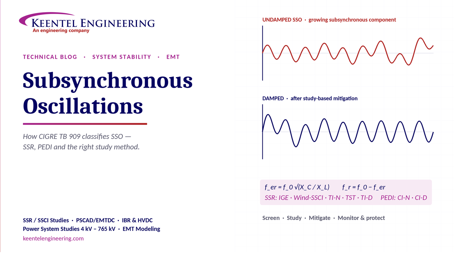
Subsynchronous oscillation (SSO) is an umbrella term for oscillatory energy exchange at frequencies below the power system's fundamental frequency. CIGRE Technical Brochure 909 (2023) organises the SSO family into two branches: subsynchronous resonance (SSR), driven by network resonance, and power electronic device interactions (PEDI), driven by converter controls. Knowing which branch and sub-type applies tells the engineer what is interacting, which study method to use and where the risk lies.
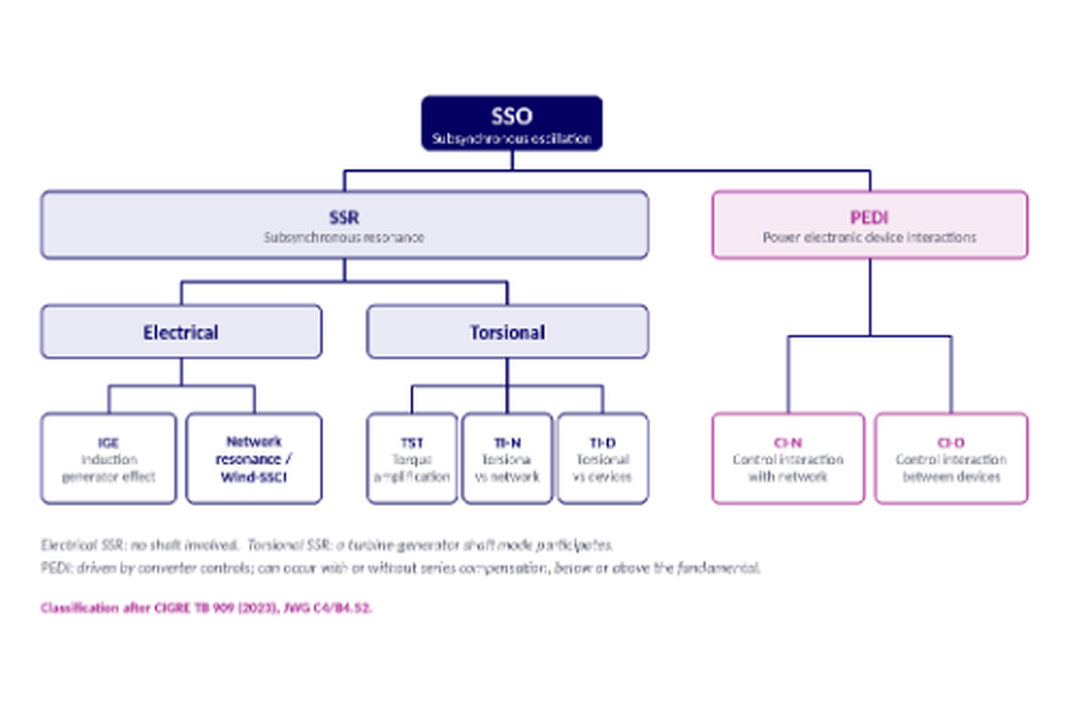
The SSO family in one table
| Branch | Type | What interacts | Typical trigger | Primary risk |
|---|---|---|---|---|
| SSR — Electrical | Induction generator effect (IGE) | Rotor circuit of a machine and a series-resonant network | Series-compensated lines, radial outage | Self-excited electrical oscillation, overvoltage |
| SSR — Electrical | Network resonance / Wind-SSCI | Series-resonant network and wind generators with their converter controls | Type 3 (DFIG) wind radially connected to series capacitors | Rapidly growing oscillation, equipment damage |
| SSR — Torsional | Torsional interaction with the network (TI-N) | Turbine-generator shaft modes and a series-resonant network | Complement of network resonance close to a shaft mode | Shaft fatigue or failure |
| SSR — Torsional | Transient torque / torque amplification (TST) | Shaft modes and switching or fault transients | Faults and reclosing near series capacitors | Large transient shaft torque, cumulative fatigue |
| SSR — Torsional | Torsional interaction with devices (TI-D) | Shaft modes and power electronic device controls | HVDC, SVC, STATCOM or IBR controls near thermal units | Negative damping of torsional modes |
| PEDI | Control interaction with the network (CI-N) | A converter's controls and the network impedance | Weak grids, series compensation, outages | Sustained or growing oscillation, plant trips |
| PEDI | Control interaction between devices (CI-D) | Controls of two or more converters, through the network | Electrically close IBR, HVDC and FACTS plants | Multi-plant oscillation, often hard to diagnose |
Why the classification matters
- It helps choose the right study method. IGE screening needs different models and data from a converter control interaction study.
- It shows what is interacting. Shaft, network, converter controls or several devices at once.
- It points to the likely risk path, and therefore to the right mitigation and protection.
Part B — How CIGRE Classifies Subsynchronous Oscillations, and Why It Matters for Your Project
A practical engineering guide to the SSO family defined in CIGRE TB 909: the physics of each mechanism, how to screen and study them, and how to mitigate them in power-electronics-dominated grids.
Why SSO is back on the agenda
For decades, subsynchronous resonance was a specialist topic for one situation: large steam turbine-generators near series-compensated transmission lines. Two shaft failures at the Mohave plant in 1970 and 1971 made the risk famous and shaped the classic SSR study methods.
The grid has changed. Wind, solar and battery plants, HVDC links, STATCOMs and other converters now make up a large and growing share of generation and grid equipment. Their fast controls interact with the network and with each other at frequencies that conventional studies were never designed to catch. Well-documented events include oscillations from Type 3 wind plants radially connected to series-compensated lines in Texas in 2009, long-running subsynchronous oscillations from series-compensated wind clusters in northern China, and converter-driven oscillations from large wind clusters in Xinjiang that tripped nearby thermal generating units in 2015.
CIGRE Joint Working Group C4/B4.52 responded with Technical Brochure 909, Guidelines for Subsynchronous Oscillation Studies in Power Electronics Dominated Power Systems (2023). Its classification gives planners, developers and equipment vendors a common language for a problem that now cuts across all of them.
The basic physics: resonance and the complementary frequency
A transmission line with series capacitor compensation forms a series L-C circuit. Its electrical resonant frequency is:
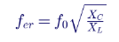
Here f_0 is the system frequency, X_C is the series capacitor reactance and X_L is the total inductive reactance of the resonant path, all at the fundamental frequency. Because compensation levels are below 100%, f_er is below f_0: it is subsynchronous.
A synchronous machine's rotor sees that stator current at the complementary frequency:
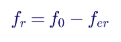
Worked example on a 60 Hz system with 40% effective compensation of the resonant path:
| Quantity | Value |
|---|---|
| Electrical resonance f_er | 60 × √0.40 ≈ 37.9 Hz |
| Complementary (rotor) frequency f_r | 60 − 37.9 ≈ 22.1 Hz |
If a turbine-generator shaft has a torsional mode near 22 Hz, the network and the shaft can exchange energy at that mode. Typical large steam units have several torsional modes in roughly the 10–50 Hz range, which is why compensation level and outage conditions must be studied together.
Branch 1 — Subsynchronous resonance (SSR)
SSR covers oscillations rooted in network resonance. TB 909 divides it into electrical SSR, which involves no mechanical system, and torsional SSR, which involves a shaft.
Electrical SSR: the induction generator effect (IGE)
At the subsynchronous frequency f_er, the machine's rotor turns faster than the stator's rotating field at that frequency. The slip is negative:
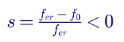
The rotor resistance, seen from the stator as R_r/s, therefore appears negative. If this negative resistance is larger than the positive resistance of the network around the resonant loop, the electrical oscillation is undamped and grows. IGE is a purely electrical phenomenon; no shaft mode is needed. It is most severe when a generator becomes radially connected to a series-compensated line after outages.
In the example above, s = (37.9 − 60) ÷ 37.9 ≈ −0.58.
Electrical SSR: network resonance and Wind-SSCI
Doubly-fed induction generator (Type 3) wind turbines have an induction-machine rotor fed by a back-to-back converter. They show a strong induction generator effect, and the rotor-side converter's current controllers can add further negative damping at subsynchronous frequencies. When such a plant is radially connected to a series-compensated line, the result can be a very fast-growing oscillation, often called subsynchronous control interaction (SSCI) or Wind-SSCI.
The 2009 Texas event is the reference case: after a line outage left a Type 3 wind plant radial to a series-compensated line, oscillations grew within a fraction of a second and damaged equipment. Wind-SSCI sits on the boundary between electrical resonance and control interaction, which is why TB 909 places it under electrical SSR while recognising the role of converter controls.
Torsional SSR: torsional interaction with the network (TI-N)
TI-N is the classic SSR of the 1970s. When the complementary frequency f_r lies close to a shaft torsional mode, the network provides negative electrical damping to that mode. If this exceeds the shaft's small mechanical damping, the torsional oscillation grows steadily and can fatigue or crack the shaft.
Torsional SSR: transient torque and torque amplification (TST)
A fault, line switching or capacitor bypass operation near a series-compensated line releases a transient at the electrical resonance. If its complementary frequency is close to a shaft mode, the shaft torque can be amplified far beyond the level caused by the same disturbance on an uncompensated system. Even when the oscillation is damped, repeated events consume shaft fatigue life. Torque amplification is a transient phenomenon, so it must be studied with time-domain simulation of credible faults and reclosing sequences.
Torsional SSR: torsional interaction with devices (TI-D)
Fast power electronic controls near a thermal generator can also interact with its shaft modes, with no series capacitor involved. The first widely reported case was an HVDC rectifier in North Dakota in the late 1970s whose current controls destabilised nearby turbine-generator torsional modes. SVCs,
STATCOMs, power system stabilisers and, increasingly, large IBR plants can do the same. TB 909 places TI-D in the torsional branch because the outcome is shaft stress, even though the cause is a device's controls.
Branch 2 — Power electronic device interactions (PEDI)
PEDI covers oscillations caused by converter controls themselves, without needing a series-resonant network or a rotating shaft. Frequencies are not restricted to the subsynchronous range; super-synchronous and near-synchronous interactions occur too.
Control interaction with the network (CI-N)
A grid-following converter synchronises with a phase-locked loop and regulates current through fast inner loops. Seen from the grid, its control system forms a frequency-dependent impedance. Over some frequency ranges, that impedance can have a negative real part, meaning the converter injects energy instead of absorbing it. If the network impedance resonates in the same range, a sustained or growing oscillation results.
Risk factors include weak grids with low short-circuit ratio, series compensation, long cable systems, high PLL or voltage-control bandwidth, and outages that leave a plant radially connected. The Xinjiang events, where direct-drive wind plants on a weak network produced subsynchronous oscillations that propagated to and tripped thermal units, show how CI-N can escalate into TI-D.
Control interaction between devices (CI-D)
When several converters sit electrically close, their controls can interact through the network: two wind or solar plants with different vendors' controls, an HVDC converter and a STATCOM, or a battery plant next to a solar plant. Each plant may be stable when studied alone yet oscillate together. CI-D is often the hardest type to diagnose, because no single owner sees the whole picture and vendor models are usually black boxes.
Why classification drives the study method
| SSO type | Screening | Detailed study | Key model data |
|---|---|---|---|
| IGE | Passive frequency scan; radial outage review | EMT simulation; eigenvalue analysis | Network R and X versus frequency; machine equivalent circuits |
| Network resonance / Wind-SSCI | Frequency scan with radial contingencies | EMT with vendor control models | Real-code wind turbine EMT models; series capacitor data |
| TI-N | Compare complementary frequencies with shaft modes | Damping (torque coefficient) analysis; eigenvalue; EMT | Shaft spring-mass data; network frequency response |
| Torque amplification (TST) | Identify faults and switching near series capacitors | EMT fault and reclosing studies; fatigue assessment | Shaft model and fatigue data; breaker sequences |
| TI-D | Unit interaction factor (UIF) | Eigenvalue analysis; EMT; device control review | HVDC, FACTS and IBR control models; shaft data |
| CI-N | Short-circuit ratio screening; impedance scan | Impedance-based stability (Nyquist); EMT | Frequency-dependent converter impedance or real-code model |
| CI-D | Electrical distance between converters | Multi-device EMT; multi-device impedance analysis | Validated EMT models of every nearby converter |
Screening tools
Unit interaction factor (UIF) estimates how strongly a power electronic device can interact with a generator:

Here S_dev is the device rating, S_i the generator rating, SC_i the short-circuit capacity at the device terminals without the generator, and SC_tot the short-circuit capacity with it. TB 909 cites screening thresholds of about 0.1 for conventional line-commutated converters and much lower, about 0.01–0.02, for voltage-source converters.
- Passive frequency scan. The network's driving-point impedance Z(f) = R(f) + jX(f) is calculated across the subsynchronous range. A reactance zero crossing with low net resistance indicates a potential resonance.
- Radiality and outage screening. Many dangerous conditions appear only after one or two outages leave a plant radially connected to series compensation. Contingency selection is as important as the method.
Detailed study methods
- Electromagnetic transient (EMT) simulation with real-code vendor models is the reference method. It captures converter controls, protection, saturation and non-linear behaviour.
- Eigenvalue (small-signal) analysis quantifies damping of every mode and shows which states participate. It needs linearised models, which are not always available for vendor controls.
- Impedance-based analysis treats each converter as a frequency-dependent impedance. Comparing converter and network impedances with Nyquist or similar criteria identifies negative-damping ranges, and works with black-box models through measured or simulated impedance scans.
- Dynamic frequency scans inject small perturbations into an EMT model to measure the impedance of plants with active controls.
TB 909 frames this as a four-phase approach: screening, detailed evaluation, mitigation planning, and monitoring and protection.
Mitigation options by type
| Category | Mitigation options |
|---|---|
| IGE and network resonance | Limit compensation level; bypass series capacitors under radial conditions; thyristor-controlled series compensation (TCSC); SSR filters; operating restrictions |
| Wind-SSCI | Converter control retuning; subsynchronous damping controllers (SSDC); automatic series capacitor bypass on radial topology; SSO detection and tripping |
| TI-N and torque amplification | Compensation limits; static blocking filters; dynamic damping devices; torsional stress relays and shaft monitoring; reclosing restrictions |
| TI-D | Supplementary damping controllers in HVDC, SVC or IBR controls; control bandwidth changes; coordinated tuning with the generator owner |
| CI-N | PLL and outer-loop retuning; active damping in the converter; grid-forming controls; synchronous condensers; network reinforcement |
| CI-D | Coordinated multi-vendor control tuning; interaction studies before energisation; operational limits; SSO monitoring |
Protection and monitoring complete the picture. SSO relays that detect subsynchronous current components, torsional stress relays on large units, and high-sample-rate waveform or PMU monitoring at IBR plants let operators detect and act on oscillations that studies did not predict.
Practical lessons for developers, utilities and owners
- Ask the classification question early. A project near series compensation, thermal units or other converters should be screened in the interconnection study phase, not after energisation.
- Study outage conditions, not just the intact system. Radial connection to series compensation is the common thread in many severe events.
- Insist on validated, real-code EMT models. Generic models cannot reproduce the control interactions that cause PEDI and Wind-SSCI.
- Study the neighbourhood. CI-D needs models of nearby plants, which requires coordination through the transmission planner.
- Plan detection and protection. Even well-studied systems change; SSO relays and monitoring are the safety net.
- Check the local requirement. Some system operators, ERCOT among them, require SSR vulnerability assessments for generation near series-compensated lines, and requirements continue to expand to converter interactions
How Keentel Engineering helps
Keentel Engineering delivers
power system studies from 4 kV to 765 kV, including EMT modelling for inverter-based resources, HVDC and FACTS interconnections.
| Stage | Keentel scope | Outcome |
|---|---|---|
| Screening | Series-compensation proximity, radial contingency review, UIF and short-circuit ratio screening, frequency scans | Early identification of which SSO types apply |
| Detailed studies | PSCAD/EMTDC EMT studies with vendor real-code models, impedance-based and frequency-scan analysis | Clear evidence of stability margins or risk |
| Model quality | EMT model review, benchmarking against positive-sequence models, model acceptance support | Models that system operators accept |
| Mitigation | Control retuning recommendations with vendors, SSDC and bypass logic requirements, protection and monitoring specifications | Practical, coordinated solutions |
| Interconnection support | SSR and SSO study reports for ISO and utility requirements, response to reviewer comments | Fewer delays in the interconnection process |
Planning a wind, solar, battery or HVDC project near series compensation or other converters? Talk to Keentel Engineering at (813) 389-7871, contact@keentelengineering.com, or book a 15-minute scoping call at calendly.com/keentel-engineering/15min.
Part C — Technical FAQ: Subsynchronous Oscillations
1. What is subsynchronous oscillation (SSO)?
SSO is any oscillatory exchange of energy in a power system at frequencies below the fundamental (60 Hz or 50 Hz). It covers both resonance-driven phenomena involving networks and rotating machines, and control-driven interactions involving power electronic devices. CIGRE TB 909 uses SSO as the umbrella term for the whole family.
2. How does CIGRE TB 909 classify SSO?
Into two branches. Subsynchronous resonance (SSR) is split into electrical SSR (induction generator effect, and network resonance / Wind-SSCI) and torsional SSR (transient torque or torque amplification, torsional interaction with the network, and torsional interaction with devices). Power electronic device interactions (PEDI) are split into control interactions with the network (CI-N) and control interactions between devices (CI-D).
3. What is the difference between SSR and PEDI?
SSR is rooted in a network resonance, usually created by series capacitors, interacting with machines and sometimes their shafts. PEDI is rooted in the control systems of power electronic devices, which can create negative damping with or without series compensation and without any rotating shaft.
4. What is the induction generator effect?
At a subsynchronous network resonance, a machine's rotor runs faster than the stator field at that frequency, so its slip is negative and its rotor resistance appears negative to the network. If that negative resistance exceeds the network's positive resistance, the electrical oscillation grows. It is purely electrical and does not require a shaft mode.
5. Why are Type 3 (DFIG) wind turbines especially exposed?
Their induction-machine rotor gives a strong induction generator effect, and the rotor-side converter's current control can add more negative damping at subsynchronous frequencies. Radially connected to a series-compensated line, a Type 3 plant can produce oscillations that grow within a fraction of a second.
6. Can Type 4 wind, solar PV and battery plants cause SSO?
Yes, through control interactions (PEDI) rather than the induction generator effect. Their full converters synchronise with a PLL and use fast current and voltage controls, which can show negative damping in weak grids or with series compensation. The risk depends on control design and tuning, so vendor-specific EMT models are essential.
7. What is torsional interaction?
It is energy exchange between a turbine-generator shaft's torsional modes and the electrical system. With the network (TI-N), a series-resonant network's complementary frequency lines up with a shaft mode. With devices (TI-D), fast controls of HVDC, FACTS or IBR plants provide negative damping to the shaft mode.
8. What is torque amplification?
A fault or switching event near a series-compensated line excites the electrical resonance. If its complementary frequency is close to a shaft torsional mode, the transient shaft torque can be much larger than for the same event on an uncompensated system. Each event uses up shaft fatigue life, even when the oscillation decays.
9. How is the electrical resonant frequency of a series-compensated line calculated?
Approximately f_er = f_0 × √(X_C ÷ X_L), using the capacitor reactance and the total inductive reactance of the resonant loop. On a 60 Hz system with 40% effective compensation, f_er is about 37.9 Hz, and a synchronous machine's rotor sees the complementary frequency of about 22.1 Hz.
10. Why are radial outages so important in SSO studies?
When outages leave a generator or IBR plant connected to the grid only through a series-compensated line, the resonance becomes much less damped and the plant interacts directly with it. Many severe SSO events occurred under exactly this condition, so contingency selection must deliberately include radial topologies.
11. What is the unit interaction factor (UIF)?
UIF is a screening index for interaction between a power electronic device and a nearby generator: the device-to-generator rating ratio multiplied by the square of one minus the ratio of short-circuit capacity without and with the generator. A high value means the generator is electrically close and could be affected. TB 909 cites thresholds of about 0.1 for line-commutated converters and about 0.01–0.02 for voltage-source converters.
12. What is a frequency scan?
A frequency scan calculates the network's impedance seen from a bus across a frequency range. A passive scan uses linear network models; a dynamic scan injects perturbations into an EMT model so converter controls are included. Reactance zero crossings with low or negative resistance flag potential resonances.
13. Why is EMT simulation considered essential?
SSO involves fast, non-linear converter controls, protection actions and interactions that positive-sequence (RMS) models average out. EMT simulation with real-code vendor models reproduces those dynamics and is the reference method for confirming or ruling out SSO risk.
14. What is impedance-based stability analysis?
Each converter is represented by its frequency-dependent impedance and the network by its own impedance. Stability is assessed by comparing them, for example with the Nyquist criterion. It is especially useful when vendors supply only black-box models, because impedance can be measured from simulation without access to source code.
15. Can SSO occur without series compensation?
Yes. Control interactions with the network (CI-N) and between devices (CI-D) can occur in weak grids, near long cables, or between electrically close converters, with no series capacitors. Torsional interaction with devices (TI-D) also needs no series compensation.
16. Are PEDI oscillations always subsynchronous?
No. Converter control interactions can occur below, near or above the fundamental frequency. Super-synchronous oscillations often appear as a pair with subsynchronous ones, mirrored around the fundamental. Study frequency ranges should be set by the control bandwidths involved, not limited to below 60 Hz.
17. How are SSO risks mitigated?
It depends on the type: limiting or bypassing series compensation, SSR blocking filters and TCSC for network resonance; supplementary damping controllers in HVDC, FACTS or IBR controls for TI-D and PEDI; converter control retuning, grid-forming controls or synchronous condensers for CI-N; and coordinated multi-vendor tuning for CI-D. Protection and monitoring provide backup.
18. What protection exists for SSO?
SSO or subsynchronous current relays detect subsynchronous components and can bypass series capacitors or trip affected plants. Torsional stress relays protect large turbine-generators. High-rate monitoring at IBR plants helps detect and diagnose oscillations early.
19. What data does an SSO study need?
A detailed network model with series capacitor and outage data, frequency-dependent network parameters, validated real-code EMT models of the project and nearby converters, plant controller settings, and, where thermal units are nearby, shaft spring-mass and damping data. Missing data is a common cause of study delays.
20. When in a project should SSO be studied?
As early as possible. Screening belongs in the interconnection study phase, once the point of interconnection and nearby series compensation, thermal units and converters are known. Detailed EMT studies should follow once the vendor and control version are selected, and be repeated if control firmware or the network changes.
References and Further Reading
Links were current at publication (October 2026).
- CIGRE Technical Brochure 909: Guidelines for Subsynchronous Oscillation Studies in Power Electronics Dominated Power Systems, CIGRE Joint Working Group C4/B4.52, August 2023.
- Dealing with interactions in modern power electronics dominated power systems, CIGRE.
- Guidelines for Subsynchronous Oscillation Studies in Power Electronics Dominated Power Systems, CIGRE UK presentation summary of TB 909.
Disclaimer
This article is general technical information for educational purposes. It is not engineering advice for any specific project and does not create a professional relationship. Frequencies, screening thresholds and mitigation options are indicative; project-specific SSO risk depends on the actual network, equipment and controls, and must be confirmed by appropriate studies with validated models.
Historical events are summarised from public technical literature. Verify the current edition of any standard or guideline before relying on it.
CIGRE, PSCAD/EMTDC and other names are the property of their respective owners. Keentel Engineering is not affiliated with or endorsed by CIGRE or any equipment manufacturer.

About the Author:
Sandip "Sonny" R. Patel, P.E.
IEEE Senior Member · Founder & CEO, Keentel Engineering
In 1995, Sonny Patel earned his Electrical Engineering degree from the University of Illinois. But degrees don't build legacies — action does.
For three decades, he has worked the power industry from every side of the table: 16 years as a utility engineer at Exelon/Commonwealth Edison; generation leadership across hydroelectric, industrial steam turbine, and a 9 GW renewable fleet; NERC Regional Entity Senior Compliance Engineer and Audit Team Lead, auditing some of the nation's largest utilities; and testing and commissioning lead on equipment up to 765 kV — the very top of the North American grid.Utility. Generator. Regulator. Consultant. Few engineers have seen all four seats. Fewer still have sat in them.
His experience spans nuclear, hydro, conventional generation, renewables, oil and gas, mining — and today's data centers, where he is authoring a three-book series on data center design. He is a Licensed Professional Engineer in six states and a Licensed Electrical Contractor in Florida (Unlimited EC) — he doesn't just design the work; he's qualified to stand behind its execution.Today, as Founder and CEO of Keentel Engineering, Sonny leads a nationwide team of engineers delivering substation design, power system studies, NERC compliance, and commissioning — done right, coast to coast.Three decades. Every side of the table. One standard: accountable engineering.
Services

Let's Discuss Your Project
Let's book a call to discuss your electrical engineering project that we can help you with.
About the Author:
Sandip "Sonny" R. Patel, P.E.
IEEE Senior Member · Founder & CEO, Keentel Engineering
In 1995, Sonny Patel earned his Electrical Engineering degree from the University of Illinois. But degrees don't build legacies — action does.
For three decades, he has worked the power industry from every side of the table: 16 years as a utility engineer at Exelon/Commonwealth Edison; generation leadership across hydroelectric, industrial steam turbine, and a 9 GW renewable fleet; NERC Regional Entity Senior Compliance Engineer and Audit Team Lead, auditing some of the nation's largest utilities; and testing and commissioning lead on equipment up to 765 kV — the very top of the North American grid.
Utility. Generator. Regulator. Consultant. Few engineers have seen all four seats. Fewer still have sat in them.
His experience spans nuclear, hydro, conventional generation, renewables, oil and gas, mining — and today's data centers, where he is authoring a three-book series on data center design. He is a Licensed Professional Engineer in six states and a Licensed Electrical Contractor in Florida (Unlimited EC) — he doesn't just design the work; he's qualified to stand behind its execution.
Today, as Founder and CEO of Keentel Engineering, Sonny leads a nationwide team of engineers delivering substation design, power system studies, NERC compliance, and commissioning — done right, coast to coast.Three decades. Every side of the table. One standard: accountable engineering.
Leave a Comment
Thank you for contacting us.
We will get back to you as soon as possible.
We will get back to you as soon as possible.
Oops, there was an error sending your message.
Please try again later.
Please try again later.
Related Posts

By SANDIP R PATEL
•
September 30, 2026
Learn NERC and ERCOT compliance requirements for natural gas power plants, including GO/GOP obligations, O&P standards, GADS reporting, and audits.

By SANDIP R PATEL
•
September 26, 2026
Learn how to prepare a MISO large-load interconnection package, including PSS®E models, BESS smoothing, harmonic data and transmission-owner requirements.

By SANDIP R PATEL
•
September 26, 2026
Learn where storage belongs in an 800 VDC AI data center, including capacitors, flywheels, BESS, fault current, protection, grounding, and EMT design.

By SANDIP R PATEL
•
September 26, 2026
Learn how SPP’s HILL and HILLGA framework works for large-load projects, including studies, BTM generation, modeling, EMT requirements, and firm service.

By SANDIP R PATEL
•
September 25, 2026
Learn how IBR time synchronization, IEEE 2800, IRIG-B verification, and PTP solutions help meet disturbance monitoring compliance requirements.

By SANDIP R PATEL
•
September 24, 2026
Learn why continuing technical training matters in power engineering, including standards, software skills, PDH requirements, and career growth.
By SANDIP R PATEL
•
September 22, 2026
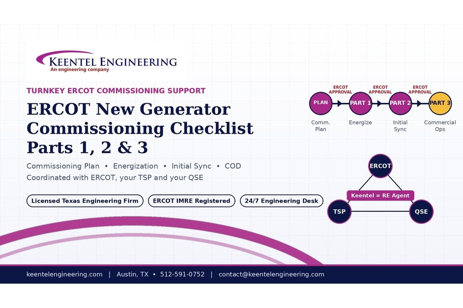
2026 ERCOT commissioning guide covering the Commissioning Plan, Checklist Parts 1–3, BESS requirements, TSP/QSE coordination, field testing and COD.

By SANDIP R PATEL
•
September 22, 2026
Learn PRC-030-1 R1 event detection requirements for inverter-based resources, SEL platforms, disturbance monitoring, and audit-ready compliance.
By SANDIP R PATEL
•
September 22, 2026
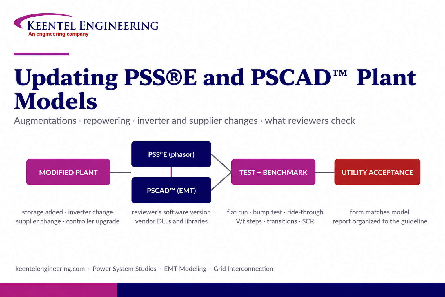
Learn how PSS®E and PSCAD™ model updates support plant augmentations, repowering, equipment changes, testing, benchmarking, and grid compliance.





