
A Coordinated Electric System Interconnection Review—the utility’s deep-dive on technical and cost impacts of your project.
Challenge: Frequent false tripping using conventional electromechanical relays
Solution: SEL-487E integration with multi-terminal differential protection and dynamic inrush restraint
Result: 90% reduction in false trips, saving over $250,000 in downtime
ERCOT enforces all of the above through simulation, which means your model is your compliance case. The bar is now high:
- Whole-facility scope. The model must represent everything the IT load, the UPS and power conversion, the cooling plant, the protection and control systems in formats compatible with ERCOT's study platforms (PSS/E, PSCAD, TSAT).
- Real control loops, not approximations. Generic textbook representations are unacceptable. The model must capture the actual inner control behavior of your power electronics.
- Hardware-validated converter models. For electronic loads, the PSCAD model must be benchmarked against actual hardware testing including voltage ride-through and subsynchronous response. A model assembled from standard PSCAD library blocks fails by definition, because a generic block has never been tested against your vendor's hardware. The good news: validation is a hardware-type test, so results for a given converter product are reusable across every facility that uses it.
- Format migration. Facilities that previously submitted the older composite load model (CMLD) format must transition to EPRI's PERC1 format.
- Three checkpoints. Models are reviewed before the stability study begins (no model, no study), before each quarterly stability assessment, and for electronic loads one final time before energization, when you must submit as-built models with a documented comparison against the previously studied data and a sworn attestation that the model matches actual field settings. ERCOT's review takes 10 business days, extendable by 20 put it on your critical path.
- A living obligation. Change your technology, controls, or relay settings in a way that affects ride-through including converting a crypto mining site to an AI data center — and you've triggered a new interconnection study, even if your megawatts don't change.
| Parameter | Detail |
|---|---|
| System | 230 kV / 138 kV transmission corridors, wind and wet-snow icing exposure |
| Data basis | 15 years of minute-resolution forced-outage records + regional weather observations |
| Core methods | Event grouping, MVA performance curves, time-to-95%-restore, area outage rate curves, fragility modeling, rerun-history benefits, exceedance and log-domain risk metrics |
| Headline result | ≈85% of maximum resilience benefit at 60% of original capital; worst-event restoration window cut from 11 days to 5 in rerun-history terms |
| Decision supported | Capital portfolio selection; resilience plan filing; post-investment verification framework |
| System / Topic | Governing Standard(s) | What It Controls |
|---|---|---|
| Overall plant electrical distribution | IEEE 141 (Red Book); IEEE 666 | Distribution architecture, voltage selection, design of generating station auxiliary service systems |
| Power system studies | IEEE 399 (Brown Book); IEEE 551 | Load flow, symmetrical/asymmetrical short circuit, motor starting methodologies down to the lowest LV panelboard |
| Protection & coordination | IEEE 242 (Buff Book); IEEE 3004.5; IEEE C37 series | Generator relaying (21, 59N, 87G), time-current coordination, selective clearing between LV and MV tiers |
| GSU / UAT / SST transformers | IEEE C57.12.00 and C57 family | Transformer ratings, impedance, testing, loading |
| HV switchyard breakers | IEEE C37.06 | AC high-voltage circuit breaker preferred ratings |
| MV switchgear (13.8 kV) | IEEE C37.20.2; IEEE C37.20.7 | Metal-clad construction, compartmentalization, vacuum breakers; arc-resistant design with plenum venting |
| MV cable | UL 1072; ICEA S-93-639 (NEMA WC 74) | Type MV-105 shielded cable, 133% insulation level for HRG systems |
| LV switchgear (480 V) | IEEE C37.13; UL 1558 | Metal-enclosed LV power circuit breaker switchgear to 635 V, draw-out ACBs with electronic trip units |
| Motor control centers | UL 845; NEMA ICS 18 | LV-MCC construction, MCCB/MCP protection for motors under ~200 HP |
| Motors | NEMA MG-1 | Motor performance, starting characteristics, service factors |
| DC & battery systems | IEEE 485; IEEE 946 | Lead-acid battery sizing (125/250 VDC), DC auxiliary system design |
| Grounding | IEEE 80; IEEE 142 (Green Book) | Ground grid step/touch potential limits; system grounding including high-resistance grounding |
| Lightning protection | IEEE 998 | Direct-stroke shielding of switchyard and outdoor generator structures |
| Arc flash & electrical safety | IEEE 1584; NFPA 70E | Incident energy calculation; worker safety boundaries and PPE |
| Fire protection | NFPA 850 | Fire protection and risk management for combustion turbine generating plants |
| Installation code | NEC (NFPA 70); NESC | Wiring methods inside the plant fence; overhead/outdoor clearances at the switchyard |
| Interconnection & compliance | FERC LGIP; NERC MOD-025/026/027, PRC-019/024/029, FAC-008 | Interconnection process, model validation, protection/ride-through coordination, facility ratings |
| IFC / Construction Deliverable | Purpose |
|---|---|
| Stamped IFC packages | Legal basis for construction; P.E. responsible charge |
| Final relay settings & TCCs | Protection as-installed matches the coordination study |
| Calculation archive | Owner records; NERC audit evidence trail |
| Commissioning procedures | Safe, sequenced energization; MOD field testing |
| Construction support | RFIs, field changes, FAT/SAT witness |
| As-builts & model handoff | Operating baseline; future study currency |
| Metric | Outcome |
|---|---|
| Defects found pre-occupancy | Three topology defects and one settings-mismatch family corrected before load migration; the shared-switchboard defect alone would have invalidated the concurrently-maintainable claim on day one |
| IST findings | Fourteen additional discrepancies surfaced under scenario testing (control logic, alarm mapping, one generator sequencing fault) — all closed before handover instead of during operations |
| Black-building test | Passed on second execution; the first attempt exposed the generator sequencing fault under true block load, exactly the failure the compressed plan would never have found |
| Handover quality | Operations team certified on the actual failure scenarios; corrected EOPs and settings documentation delivered as controlled documents |
| Business outcome | Occupancy proceeded three weeks behind the original date — against an independent estimate that the uncorrected sequencing fault carried a high probability of a full facility outage within the first year |
Part 2 — Frequently Asked Questions: Large Load Interconnection
An electric grid must remain in continuous balance — generation onto the grid must equal consumption from it at every instant. PJM achieves this balance, and prices it, through a layered market architecture. Each layer operates on a different time horizon, and each one touches project economics differently.
| Domain | Key Standards / Codes | What They Govern |
|---|---|---|
| Fire safety | NFPA 855; UL 9540 / UL 9540A | Installation requirements, separation, gas management; system safety listing and thermal-runaway fire testing |
| Grid interconnection | IEEE 1547 (distribution); IEEE 2800 (transmission IBRs) | Ride-through, reactive capability, power quality, and performance at the point of interconnection |
| Power quality | IEEE 519 | Harmonic distortion limits at the PCC |
| Protection & grounding | IEEE 80 / 81 / 142; C37 series | Grounding system design and testing; protective relaying |
| Reliability compliance | NERC standards (incl. PRC ride-through requirements) | Registered-entity obligations for grid-connected storage |
Twelve Electrical Safety Rules Every Engineer Must Know
Aug 27, 2026 | Blog
And the OSHA, NFPA 70E, NESC, NEC and IEEE requirements that sit behind each one
Why the Poster on the Wall Is Not a Safety Program
Walk into almost any electrical contractor trailer, substation control building or plant maintenance shop and you will find a laminated poster listing ten or twelve electrical safety rules. De-energize. Lock out. Test before you touch. Wear your PPE. The rules are correct, they are memorable, and they are not sufficient. A poster tells a worker what to do. It does not tell them how the requirement is written, when an exception legitimately applies, who is authorized to approve that exception, or what engineering work has to happen months earlier so that the rule can actually be followed on the day.
That gap is where people get hurt. A technician who has memorized "always de-energize" but has never seen an energized electrical work permit will improvise when a plant manager says the line cannot come down. A crew that knows to "wear PPE" but works from an arc flash label produced from a study that was never updated after a transformer replacement is wearing the wrong PPE with complete confidence. A field engineer who was taught that clearances come from the National Electrical Code will apply the wrong clearance table entirely when working near an overhead distribution circuit, because the NEC does not govern utility overhead lines.
This article takes the twelve rules that appear on those posters and does what the poster cannot: connects each one to the governing requirement, explains the failure mode it is guarding against, and identifies the engineering decision that determines whether the rule is easy or nearly impossible to follow in the field. Electrical safety is not primarily a behavioral problem. It is a design problem with a behavioral layer on top.
Who this is written for
Field engineers, commissioning engineers and construction managers working on energized or recently energized systems.
EHS managers and safety directors who need to understand the technical basis for the rules they enforce.
Owners and developers who are deciding how much engineering to fund before a facility goes into service.
Anyone signing an energized electrical work permit — the signature carries the technical judgment.
The Regulatory Stack: Five Documents, Five Different Jobs
The single most common source of confusion in electrical safety is treating "the code" as one document. In the United States there are at least five separate instruments in play, they have different legal force, and they apply to different installations. Before discussing any individual rule, it is worth being precise about which document is doing the work.
| Document | What it is | What it governs |
|---|---|---|
| OSHA 29 CFR 1910.331–.335 | Federal regulation — legally enforceable | Safety-related work practices for general industry employees working on or near exposed energized parts |
| OSHA 29 CFR 1910.269 | Federal regulation — legally enforceable | Operation and maintenance of electric power generation, transmission and distribution installations, including utility and utility-equivalent work |
| OSHA 29 CFR 1910.147 | Federal regulation — legally enforceable | The Control of Hazardous Energy (Lockout/Tagout) for servicing and maintenance of machines and equipment |
| NFPA 70E | Consensus standard — adopted by reference, cited by OSHA as evidence of feasible practice | Electrical safe work practices: shock and arc flash risk assessment, boundaries, PPE selection, EEWP, absence-of-voltage verification |
| NFPA 70 (NEC) | Consensus standard — adopted into law by most states and jurisdictions | Installation requirements for premises wiring. NEC 90.2 excludes utility-owned generation, transmission and distribution installations |
| ANSI C2 (NESC) | Consensus standard — adopted by most states for utility systems | Design, construction, operation and maintenance of utility supply lines and substations, including overhead and underground clearances |
| IEEE 1584, IEEE 80, IEEE C57 series | Engineering standards — methodology, not law | Incident energy calculation, substation grounding and step/touch potential, transformer loading and testing methods |
The practical implication is direct. If you are working inside a commercial or industrial facility, your work practice obligations flow from 1910.331–.335 and your PPE and boundary decisions from NFPA 70E, while the installation itself was built to the NEC. If you are working in a substation, on a transmission line, or inside a generating station, 1910.269 governs your work practices and the installation was built to the NESC. Applying NEC working-space rules to a 138 kV switchyard, or NESC clearances to a 480 V motor control center, produces answers that are not merely conservative or liberal — they are the wrong answers to the wrong question.
A correction worth making
Safety graphics frequently state that clearance from overhead power lines is "per NEC/IEC." In the United States this is incorrect. Design clearances for overhead supply conductors come from the NESC (ANSI C2). Minimum approach distances for workers come from OSHA 1910.333(c)(3) for general industry and OSHA 1910.269 Table R-3 through Table R-8 for qualified line work. The NEC explicitly excludes utility-owned outdoor supply installations from its scope.
This is not pedantry. The distances differ materially, and citing the wrong document in a job hazard analysis will not survive an incident investigation.
The Twelve Rules, Read as an Engineer Would Read Them
1. Always De-Energize — And Understand the Only Two Exceptions
OSHA 1910.333(a)(1) states the requirement plainly: live parts to which an employee may be exposed shall be de-energized before the employee works on or near them. It then provides two, and only two, permissible bases for working energized. The first is that de-energizing introduces additional or increased hazards — the classic examples are shutdown of life-support equipment, deactivation of emergency alarm systems, and shutdown of hazardous location ventilation. The second is that de-energizing is infeasible due to equipment design or operational limitations, which covers testing that can only be performed on an energized circuit and troubleshooting that cannot be done on a dead system.
Neither exception is a schedule exception. Production pressure, a customer who does not want an outage, a commissioning milestone, and the cost of a shutdown are not, on their own, legal justifications. NFPA 70E 130.2(A) mirrors this and adds the explicit clarification that additional hazards or infeasibility must be demonstrated, not asserted. Where energized work is genuinely justified, NFPA 70E 130.2(B) requires an Energized Electrical Work Permit documenting the circuit, the justification, the results of the shock and arc flash risk assessments, the PPE required, the means of restricting access, and the approving signatures.
The test to apply on site is simple. If someone cannot articulate which of the two exceptions applies, and cannot produce a signed permit that says so, the work is not authorized. That conversation is easier to have before the crew is mobilized than at the switchgear door.
Design lever: The number of energized work permits a facility issues is an engineering outcome, not a discipline outcome. Redundant feeds, properly placed isolation devices, drawout breakers, load-break switching, and dual-source designs are what make de-energizing feasible. Facilities that write permits every week usually have a single-line diagram problem, not a culture problem.
2. Lockout/Tagout — Know Which Rule You Are Under
Three OSHA provisions address the control of hazardous electrical energy and they are not interchangeable. 1910.147 is the general lockout/tagout standard for servicing and maintenance of machines and equipment. 1910.333(b) covers lockout and tagging for the specific case of working on de-energized electrical circuits. 1910.269(d) applies to generation, transmission and distribution work and includes its own hazardous energy control requirements, alongside 1910.269(m) for de-energizing lines and equipment for employee protection.
The sequence that satisfies all three is the same in structure: identify every energy source feeding the equipment, notify affected personnel, shut down using the normal operating sequence, isolate each source with a disconnecting means, apply a lock and a tag to each isolating device, release or restrain all stored energy, and then verify isolation by test. Each authorized employee applies their own lock.
Group lockout devices and lockbox arrangements are permitted, but they must preserve individual control — no worker should be relying on someone else remembering to keep them safe.
The step most commonly compressed is stored energy release. Capacitor banks, filter capacitors in drives, station battery systems, UPS units, DC buses in battery energy storage systems, charged cables, and springs in stored-energy breaker mechanisms all hold energy after the upstream source is open. Isolation of the AC source does not address any of them.
Backfeed deserves separate attention. Standby generators, parallel inverters, photovoltaic arrays energized by daylight regardless of any switch position, control power transformers fed from a different bus, and instrument transformer secondaries can all re-energize equipment that appears isolated. A lockout that traces only the primary feed is incomplete.
Design lever: Complete, current single-line diagrams with every source, tie and backfeed path shown are the difference between a lockout that works and one that misses a circuit. Where drawings are stale, a field verification and as-built update is a safety deliverable, not a documentation task.
3. Verify Before You Touch — Live, Dead, Live
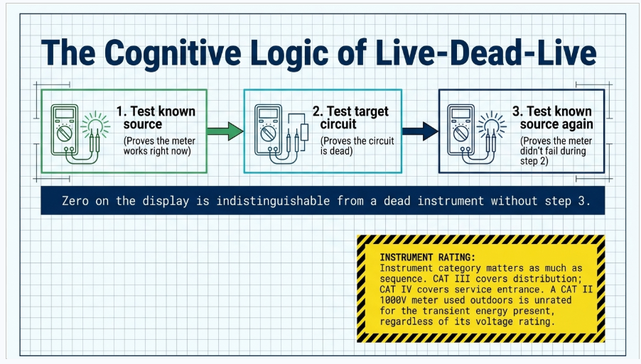
NFPA 70E 120.6 establishes the process for establishing an electrically safe work condition, and the verification step is specific: an adequately rated portable test instrument shall be used to test each phase conductor or circuit part to verify it is de-energized, and the test instrument shall be verified as operating satisfactorily on a known voltage source before and after the test. This is the live-dead-live sequence. Testing the meter on a known source first proves it works; testing the circuit proves the circuit is dead; testing the known source again proves the meter did not fail between the first two steps.
The failure mode this guards against is not exotic. A blown internal fuse, a broken lead, a depleted battery, or a meter left in the wrong function will all display zero volts on a fully energized 480 V bus. Without the closing verification, zero on the display is indistinguishable from a dead instrument.
Instrument rating matters as much as sequence. Test instruments used on circuits above 50 V must be rated for the voltage and, critically, for the measurement category of the location. IEC 61010-1 category ratings reflect available fault energy, not just voltage: CAT III for distribution-level and fixed installation work, CAT IV for the service entrance and outdoor supply. A CAT II 1000 V meter used at a service entrance is rated for the voltage and unrated for the transient energy present there. NFPA 70E 110.4(A) also requires that instruments and leads be visually inspected for damage before each use.
Where opening the enclosure is itself the hazardous step, NFPA 70E 120.6(7) permits a permanently mounted absence-of-voltage tester listed to UL 1436 to satisfy the verification, eliminating the need to open the door to test. On new switchgear and MCC procurements this is a low-cost specification item with a direct risk reduction.
Design lever: Specify permanently mounted absence-of-voltage testers and voltage indicators on new medium-voltage and 480 V equipment. Specify infrared inspection windows so thermographic surveys do not require opening doors. Both remove routine energized exposure from the maintenance program permanently.
4. Use PPE — But Know Which Selection Method You Are Using
NFPA 70E permits two mutually exclusive methods for selecting arc flash PPE, and mixing them is a documented error. The incident energy analysis method under 130.5(G) uses calculated incident energy in cal/cm², typically from IEEE 1584-2018, and selects arc-rated clothing and equipment with an arc rating equal to or greater than that value at the working distance. The arc flash PPE category method under 130.7(C)(15) uses tables that specify a category based on equipment type, voltage, available fault current and clearing time, provided the installation falls within the stated parameters. The two methods shall not be used on the same piece of equipment for the same task.
Shock PPE is a separate assessment governed by 130.4. Rubber insulating gloves meeting ASTM D120 and OSHA 1910.137, with leather protectors, are selected by class for the nominal voltage. Under 1910.137(c)(2)(viii), rubber insulating gloves must be electrically tested before first issue and at intervals not exceeding six months thereafter; sleeves at twelve months. Gloves that have exceeded the test interval are not PPE, regardless of appearance.
Arc-rated clothing must meet ASTM F1506 and the entire system matters. A 12 cal/cm² arc-rated shirt worn over a polyester undershirt is not a 12 cal/cm² system — meltable synthetic fabrics underneath can ignite or melt to skin. Arc-rated face shields with balaclavas, or arc flash suit hoods above 12 cal/cm², protect the head and neck; safety glasses alone do not. Dielectric footwear provides secondary protection only and is never the primary shock control.
One point deserves emphasis because it is routinely misunderstood. Arc-rated PPE is designed to reduce the severity of a second-degree burn to a survivable level at the calculated working distance. It is not designed to make an arc flash a non-event, and it does not protect against the pressure wave, molten metal spray, or blunt trauma from equipment failure. PPE is the last control in the hierarchy, not the first.
Design lever: Incident energy is a calculated result, and it is calculable in advance. Fault current sources, protective device settings, clearing times and working distances are all engineering variables that Keentel adjusts during coordination studies to bring incident energy down before PPE is ever selected.
5. Use the Right Tools — Rated, Tested and Undamaged
OSHA 1910.335(a)(2)(i) requires insulated tools or handling equipment when working near exposed energized conductors where contact is possible, and requires that the insulating capability be appropriate for the voltage. Insulated hand tools for work up to 1000 V AC are manufactured and tested to ASTM F1505 and marked with the double-triangle 1000 V symbol. Tools that are merely dipped in plastic, comfort-gripped, or wrapped in tape are not insulated tools.
Live-line tools for medium and high voltage work fall under ASTM F711 for fiberglass-reinforced plastic rod and tube. OSHA 1910.269(j) requires that live-line tools be wiped clean and visually inspected before use each day, and removed from service and tested if any defect or contamination that could adversely affect the insulating qualities is found. Surface contamination and moisture absorption are the mechanisms that matter; a hot stick that has been left leaning against a fence in the rain is not a hot stick.
Insulated blankets, line hose, and covers under ASTM F479 and F478 provide secondary protection where accidental contact with adjacent parts is credible. They are not a substitute for de-energizing and are inspected before each use.
Two further practices belong here. First, non-conductive ladders — fiberglass, not aluminum — near any potentially energized circuit. Second, torque tools calibrated and used to the manufacturer specification on every electrical termination. Loose connections are the leading cause of thermal failure and one of the leading initiators of arc faults in distribution equipment; a calibrated torque wrench is a safety tool.
6. Keep the Work Area Safe — Illumination, Barriers and Boundaries
OSHA 1910.333(c)(4) prohibits employees from entering spaces containing exposed energized parts unless illumination is provided that allows the work to be performed safely, and prohibits reaching blindly into areas that may contain energized parts. Poor lighting inside a switchgear lineup is a recognized hazard, not an inconvenience.
Access control is governed by NFPA 70E 130.7(E), which requires safety signs, barricades and, where the situation warrants, an attendant to prevent unqualified persons from entering the arc flash boundary or approaching energized parts. Conductive barricade tape is prohibited near energized conductors. The arc flash boundary is the distance at which incident energy falls to 1.2 cal/cm² — the onset of a second-degree burn on bare skin — and inside it, anyone present requires arc-rated protection, including observers, apprentices and the project manager who wandered over to watch.
Wet conditions materially increase shock severity by lowering contact resistance, and 1910.333(c)(2) addresses conductive materials and equipment handled near energized parts. Standing water, damp concrete, and wet PPE all change the risk picture. In outdoor substation work, the same conditions raise step and touch potential exposure.
Housekeeping is not cosmetic. Egress from in front of switchgear during an arc fault is measured in fractions of a second, and equipment stored in the working space, in violation of NEC 110.26 dedicated space and working clearance requirements, becomes a trip hazard at exactly the wrong moment.
7. Follow Clearances — And Use the Correct Table
Three distinct sets of distances get called "clearance" and they are not the same thing.
Design clearances are the permanent physical separations built into an installation: NESC Rule 232 for vertical clearances of overhead conductors above ground, roadways and buildings, and NESC Rule 234 for clearances to buildings, signs and other installations. For premises wiring, NEC 110.26 establishes working space depth, width and headroom in front of electrical equipment, and NEC 110.34 does the same for equipment over 1000 V. These are installation requirements checked at design and inspection.
Approach boundaries are work practice distances from NFPA 70E 130.4. The limited approach boundary is the distance beyond which unqualified persons may not approach without an escort. The restricted approach boundary is the distance within which only qualified persons using shock PPE and working under a documented plan may go. Representative AC values from Table 130.4(E)(a) illustrate the scale, though the current edition governs and must be consulted directly.
Minimum approach distances for qualified line workers are separate again, from OSHA 1910.269(l) and its accompanying tables, and from 1910.333(c)(3) for general industry work near overhead lines. For work near overhead lines by unqualified persons and for vehicle and equipment operation near lines, 1910.333(c)(3)(iii) sets the familiar 10-foot minimum for lines up to 50 kV, increasing above that voltage.
Crane, aerial lift and material handling operations near energized lines are the highest-consequence application of this rule. The controlling requirement is a documented determination of line voltage, the corresponding minimum clearance, and a physical means of maintaining it — a dedicated spotter, range limiting, or de-energizing and grounding the line.
| Nominal system voltage (AC, phase-to-phase) | Limited approach — exposed movable conductor | Limited approach — exposed fixed circuit part | Restricted approach boundary |
|---|---|---|---|
| 50 V – 150 V | 10 ft 0 in | 3 ft 6 in | Avoid contact |
| 151 V – 750 V | 10 ft 0 in | 3 ft 6 in | 1 ft 0 in |
| 751 V – 15 kV | 10 ft 0 in | 5 ft 0 in | 2 ft 2 in |
| 15.1 kV – 36 kV | 10 ft 0 in | 6 ft 0 in | 2 ft 7 in |
Representative values shown for illustration of the concept only. The current edition of NFPA 70E Table 130.4(E)(a), and the applicable OSHA tables for line work, govern in all cases.
8. Check Equipment — The "Normal Operating Condition" Test
NFPA 70E 130.2(A)(4) contains one of the most operationally important provisions in the standard, and it is frequently overlooked. Equipment is considered to be in a normal operating condition only when all five of the following are true: the equipment is properly installed; the equipment is properly maintained; all equipment doors are closed and secured; all covers are in place and secured; and there is no evidence of impending failure.
This matters because the risk assessment for tasks like operating a circuit breaker or a disconnect depends on the equipment being in normal operating condition. A switchgear lineup with a cracked bushing, an open panel cover, evidence of overheating or arcing tracks, water intrusion, corrosion, or no maintenance record is not in normal operating condition, and the likelihood of an arc flash event during operation increases accordingly. The task that was previously assessed as low risk is no longer that task.
"Properly maintained" is a defensible claim only where records exist. NFPA 70B, now issued as a standard rather than a recommended practice, establishes the electrical equipment maintenance program framework — condition assessment, intervals, testing and documentation. For protection systems on the bulk electric system, NERC PRC-005 imposes mandatory maintenance and testing intervals with auditable evidence. A protective relay that has not been tested to its PRC-005 interval cannot be assumed to clear a fault in the time the arc flash study used.
Inspection findings need a route to resolution. "Report any defects immediately" only functions where there is a defined recipient, a defined authority to remove equipment from service, and a work order system that closes the loop. Otherwise defects are reported into a void and the same finding appears in next year report.
Design lever: Arc flash results depend on protective device clearing time. If relay and breaker maintenance lapses, the calculated incident energy on every label in the facility silently becomes optimistic. Maintenance program integrity is an input to the study, not a separate topic.
9. Do Not Overload — Design Margin Is a Safety Margin
Overload is usually presented as a housekeeping rule about extension cords. It is more usefully understood as the field-level expression of a design constraint. NEC 210.19 and 215.2 establish conductor sizing for branch circuits and feeders, and NEC 210.20(A) and 215.3 require that overcurrent devices supplying continuous loads be sized at not less than 125 percent of the continuous load — the familiar 80 percent rule expressed from the other direction.
Ampacity is not a single number. NEC 310.16 values are subject to ambient temperature correction under 310.15(B) and adjustment for more than three current-carrying conductors in a raceway. Terminal temperature limitations under 110.14(C) frequently control the final answer, and a conductor selected from the 90°C column but landed on 75°C-rated terminations is limited by the terminations. For underground and duct bank installations, IEEE 835 and Neher-McGrath methods and soil thermal resistivity determine real capacity, often well below table values.
For transformers, IEEE C57.91 governs loading above nameplate and the relationship between load, temperature and insulation life. Sustained overload does not trip anything; it consumes insulation life and eventually produces a failure that is both an outage and an arc flash source.
Flexible cords and temporary power on construction sites carry their own requirements under NEC Article 400 and OSHA 1926 Subpart K, including GFCI protection or an assured equipment grounding conductor program. Daisy-chained relocatable power taps and cords run through doorways or under carpet remain among the most common findings in facility inspections.
10. Use Proper Labeling — The Label Is an Engineering Deliverable
NEC 110.16(A) requires field-applied arc flash warning labels on switchboards, switchgear, panelboards, industrial control panels, meter socket enclosures and motor control centers in other than dwelling units, where the equipment is likely to require examination, adjustment, servicing or maintenance while energized. NEC 110.16(B) adds a requirement for service equipment rated 1200 A or more to carry a label with specific arc flash information.
The content requirement is in NFPA 70E 130.5(H). The label shall contain the nominal system voltage, the arc flash boundary, and at least one of the following: available incident energy and the corresponding working distance; minimum arc rating of clothing; site-specific level of PPE; or the arc flash PPE category from the tables, where that method is used. Labels shall be legible, durable, and consistent with ANSI Z535.4 formatting. Where the incident energy analysis method is used, the label must state the date of the study and the review interval.
NFPA 70E 130.5 requires the arc flash risk assessment to be reviewed at intervals not to exceed five years, and whenever a major modification or renovation occurs, or when changes in overcurrent protective devices or upstream system capacity render the results invalid. A utility service upgrade, a new transformer, a generator addition, or a relay setting change all potentially invalidate every downstream label.
Beyond arc flash, the labeling regime includes NEC 408.4 circuit directories and source identification for panelboards, NEC 110.22 marking of each disconnecting means with its purpose, NEC 110.21(B) requirements for field-applied hazard markings, and equipment nameplate and circuit identification consistent with the single-line diagram. A lockout is only as good as the ability to identify the correct disconnect, and a mislabeled panel is a shock hazard with a delay fuse on it.
Design lever: Labels are the visible output of the short circuit, coordination and arc flash study chain. A facility with unlabeled or expired equipment does not have a labeling problem; it has an unfinished or outdated power system study.
11. Respect Energy — Assume Live Until Proven Dead
The instinct behind this rule is correct and worth restating in engineering terms: electricity provides no sensory warning, and several energy sources present in modern facilities are not intuitive.
Instrument transformer secondaries are the classic example. A current transformer secondary must never be open-circuited while the primary is energized — the CT will attempt to drive its magnetizing current through an open circuit and can develop lethal secondary voltages and destroy itself. Shorting blocks exist for this reason and their use is not optional. Voltage transformer secondaries can backfeed the primary if energized from the secondary side, re-energizing a "dead" bus at full primary voltage.
Capacitive coupling and induction on de-energized conductors running parallel to energized circuits — a de-energized transmission circuit on a double-circuit structure, a de-energized cable in a shared duct bank — can produce dangerous voltages and currents on a line that has been properly isolated. This is why protective grounding under OSHA 1910.269(n) exists: grounds are applied to provide a path that limits the voltage a worker can be exposed to, and they must be rated for the available fault current, applied in the correct sequence, and placed so the worker is within the protected zone.
DC systems are increasingly the exposure. Station batteries in substations, DC buses in battery energy storage systems, photovoltaic array DC that is energized whenever there is light regardless of any switch position, and drive DC links with capacitor storage all persist after AC isolation. DC arc faults do not have a natural current zero and behave differently from AC arcs; DC arc flash analysis requires a different methodology than IEEE 1584, which is an AC method.
Step and touch potential in substation and line work is the failure mode that kills people who never touched a conductor. During a ground fault, the earth surface develops a voltage gradient; the difference between the potential at a person hand contact point and their feet, or between their two feet, drives current through the body. IEEE 80 is the governing design methodology, and an adequate ground grid, surface layer resistivity and equipment bonding are what keep those potentials below tolerable limits.
Design lever: Grounding design under IEEE 80, protective grounding procedures, and DC-specific arc flash analysis for BESS and PV installations are engineering scopes, not field procedures. Where they are missing, no amount of field discipline substitutes.
12. Be Trained and Alert — Qualified Means Something Specific
OSHA 1910.399 defines a qualified person as one who has received training in and has demonstrated skills and knowledge in the construction and operation of electric equipment and installations and the hazards involved. NFPA 70E 110.6 expands this: a qualified person must be able to distinguish exposed energized parts, determine nominal voltage, know the approach distances and the corresponding voltages, understand the process of risk assessment and hazard elimination, and be able to select and use the appropriate PPE. Qualification is task-specific and equipment-specific. A person qualified on 480 V motor control is not thereby qualified on 15 kV switchgear.
Retraining is required at intervals not to exceed three years under NFPA 70E 110.6(D)(3), and additionally when work practices change, when new equipment or procedures are introduced, or when supervision or annual inspection indicates the employee is not complying with safe work practices.
The job briefing requirement under OSHA 1910.269(c) is one of the highest-value and lowest-cost controls available. Before each job, the person in charge covers the hazards, work procedures, special precautions, energy source controls and PPE requirements. For repetitive or similar work during the same day, an abbreviated briefing is permitted, but a briefing at the start of each shift is required. NFPA 70E 110.5(C) requires an equivalent briefing and, for work within the limited approach boundary or the arc flash boundary, a documented job safety plan.
Distraction and complacency are named on every poster because they are real, but the engineering-adjacent point is that the most dangerous condition is a routine task performed on equipment whose condition has changed. The crew is not less alert; the equipment is different from the last time. That is precisely what Rule 8 exists to catch.
Where Safety Is Actually Decided: The Design Phase
Every rule above assumes an installation someone already built and a study someone already performed. The severity of the hazard a worker faces was fixed long before they arrived. Incident energy, available fault current, clearing time, isolation flexibility, approach requirements and step and touch potential are all determined at design, procurement and settings. The field crew inherits the number; they do not set it.
That is the argument for treating
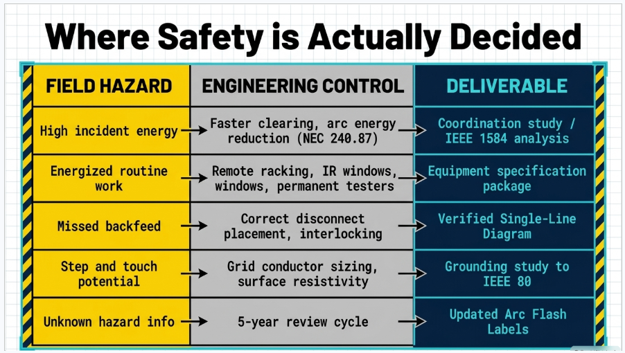
power system studies as a safety investment rather than a compliance expense. The table below maps the common hazards back to the engineering control that reduces them and the deliverable that documents it.
| Hazard | Engineering control | Deliverable |
|---|---|---|
| High incident energy at MCC and switchgear | Faster clearing through relay coordination, instantaneous elements, maintenance mode / arc energy reduction per NEC 240.87, current-limiting devices, arc flash relaying | Short circuit and coordination study; incident energy analysis to IEEE 1584-2018 |
| Energized work exposure during routine operations | Remote racking, remote switching, permanently mounted absence-of-voltage testers to UL 1436, IR inspection windows, arc-resistant switchgear to IEEE C37.20.7 | Equipment specification and procurement package |
| Step and touch potential in substations | Ground grid conductor sizing and spacing, surface layer resistivity, equipment bonding, fence grounding | Grounding study to IEEE 80 with soil resistivity testing |
| Incomplete isolation and missed backfeed | Correct disconnect placement, source identification, tie interlocking, key interlock schemes | Verified single-line diagram, switching and tagging procedures |
| Undersized or thermally limited conductors | Ampacity analysis with derating, duct bank thermal modeling, terminal temperature verification | Cable sizing and ampacity study |
| Protection that does not operate as assumed | Relay settings verification, functional testing, maintenance intervals | Relay setting files and PRC-005 compliant maintenance program |
| Unknown or expired hazard information | Study refresh triggered by system changes, five-year review cycle | Updated arc flash labels with study date and review interval |
The economics are not close
A single arc flash injury carries direct medical costs frequently exceeding one million dollars, plus outage cost, equipment replacement, OSHA penalties, litigation and insurance consequences. A facility-wide short circuit, coordination and arc flash study is a small fraction of that figure, and it is performed once with periodic updates.
The study also produces settings that improve selectivity, a verified single-line diagram, and documentation that survives an incident investigation. There is n
A Practical Sequence for Facilities Starting from Zero
- Field-verify the single-line diagram, including every source, tie, backfeed path and disconnecting means. Nothing downstream is valid without this.
- Obtain utility available fault current and clearing data at the point of service, and equipment nameplate and cable data throughout.
- Perform the short circuit study and confirm equipment interrupting and withstand ratings are adequate for present and projected fault duty.
- Perform the protective device coordination study, resolving selectivity against clearing time — recognizing that slower is more selective and more dangerous.
- Perform the arc flash incident energy analysis to IEEE 1584-2018 and identify locations above practical PPE limits.
- Implement mitigation where incident energy is excessive: settings changes, maintenance mode switches, arc energy reduction, equipment replacement.
- Produce and apply labels compliant with NEC 110.16 and NFPA 70E 130.5(H), with study date and review interval.
- Write the electrical safety program, EEWP process and job safety plan templates around the results, and train qualified persons on the actual equipment.
- Establish the maintenance program to NFPA 70B, and PRC-005 where applicable, so the clearing times the study assumed remain true.
- Set the review trigger: five years maximum, and immediately on any change to sources, protective devices or major equipment.
In an Emergency
The response sequence taught on posters is correct and worth stating with the reasoning attached. Do not touch a victim who may still be in contact with an energized conductor — rescuer electrocution is a documented and recurring outcome. De-energize the source if it can be done immediately and safely; otherwise use an approved insulated contact-release tool rated for the voltage. Call for emergency medical response immediately; electrical contact injuries include cardiac arrhythmia and deep tissue damage that are not visible externally and require evaluation even where the victim appears uninjured.
NFPA 70E 110.6(C) requires emergency response training for employees exposed to shock hazards, including first aid, CPR and AED use, with annual verification of CPR and AED competence and annual verification of contact release training. OSHA 1910.269(b) sets first aid and CPR availability requirements for line work. Preserve the scene and equipment condition for investigation, and report the incident through the established process — the corrective action that prevents the next event depends on accurate information from this one.
Frequently Asked Questions
Effectively yes, with two narrow exceptions. OSHA 1910.333(a)(1) requires de-energizing unless the employer can demonstrate that de-energizing introduces additional or increased hazards, or that it is infeasible due to equipment design or operational limitations. Cost, schedule, customer preference and production pressure are not among the exceptions. Where an exception applies, NFPA 70E 130.2(B) requires a documented and signed Energized Electrical Work Permit.
Testing, troubleshooting and diagnostics that cannot be performed on a de-energized circuit are the standard examples of infeasibility. Additional hazards include shutting down life-support equipment, deactivating emergency alarm or fire protection systems, and shutting down ventilation serving a hazardous location. The determination should be documented on the permit, with the technical reason stated, not simply asserted.
NFPA 70E requires approval signatures from the responsible parties within the employer organization — typically the person responsible for the safety program plus management authorized to accept the residual risk, and often the facility owner where a contractor is performing the work. The signature is a technical judgment that the exception genuinely applies and that the controls documented are adequate. It should not be delegated to whoever is available.
1910.147 is the general control of hazardous energy standard covering servicing and maintenance of machines and equipment. 1910.269(d) applies to electric power generation, transmission and distribution work and includes its own hazardous energy control provisions, with 1910.269(m) addressing de-energizing lines and equipment for employee protection. 1910.333(b) addresses lockout and tagging specifically for work on de-energized electrical circuits in general industry. The correct standard depends on the installation and the nature of the employer operations, and the answer determines the required procedure, training and documentation.
No. Testing the instrument on a known live source before the measurement proves it works at that moment. Testing again after the measurement proves it did not fail between those two points. A meter with a blown internal fuse, a broken lead or a depleted battery reads zero volts on a fully energized bus, and without the second verification that zero is indistinguishable from a dead circuit. The sequence is required by NFPA 70E 120.6.
Yes, within limits. NFPA 70E 120.6(7) permits a permanently mounted absence-of-voltage tester listed to UL 1436 to be used to verify the absence of voltage, provided it is installed and used in accordance with its listing and the equipment is otherwise properly isolated. This is one of the highest-value specification items available on new switchgear and MCC purchases because it removes a routine energized exposure entirely.
The IEC 61010-1 measurement category reflects the transient energy available at the point of measurement, not merely the voltage. CAT III is intended for distribution-level and fixed installation measurements; CAT IV for the origin of the installation, service entrance and outdoor supply. A meter rated CAT II 1000 V is rated for the voltage at a service entrance but is not rated for the transients present there. Match both the category and the voltage to the location, and inspect leads and instrument for damage before every use.
An incident energy analysis is the more accurate method and is preferred wherever a study exists, because it gives an actual cal/cm² value at a defined working distance and enables mitigation. The category tables in NFPA 70E 130.7(C)(15) are a permitted alternative but only where the installation is within the stated parameters for available fault current and clearing time, which must be verified. The two methods shall not be used on the same equipment for the same task.
Under OSHA 1910.137(c)(2)(viii), rubber insulating gloves must be electrically tested before first issue and every six months thereafter; insulating sleeves at twelve months. Gloves that have not been tested within the interval may not be used. In addition, gloves must be air-tested and visually inspected by the user before each use, and leather protectors are required over rubber gloves except in the limited circumstances the standard permits.
They address different hazards. The arc flash boundary is the distance at which incident energy from an arcing fault falls to 1.2 cal/cm², the threshold for the onset of a second-degree burn on bare skin. The limited approach boundary is a shock protection distance based on system voltage, marking where unqualified persons may not go unescorted. The two are calculated differently and, depending on the equipment, either can be the larger.
No. NEC 90.2 excludes utility-owned installations for generation, transmission and distribution from the scope of the Code. Design clearances for overhead supply conductors come from the NESC (ANSI C2). Worker approach distances near overhead lines come from OSHA — 1910.333(c)(3) for general industry, including the 10-foot rule for lines up to 50 kV, and 1910.269(l) with its tables for qualified line work. The NEC does govern working space around premises electrical equipment under 110.26 and 110.34, which is a different question.
NFPA 70E 130.2(A)(4) defines it as all five of: properly installed, properly maintained, doors closed and secured, covers in place and secured, and no evidence of impending failure. It matters because the risk assessment for operating equipment assumes normal operating condition. Equipment showing overheating, arcing tracks, corrosion, water intrusion, physical damage or no maintenance record fails the test, and the task must be reassessed with a higher likelihood of an arcing event.
NFPA 70E 130.5 requires the arc flash risk assessment to be reviewed at intervals not exceeding five years, and to be updated whenever a major modification or renovation occurs or when changes to overcurrent protective devices or system capacity could invalidate the results. In practice, a utility service change, a new or replaced transformer, added generation or storage, a switchgear replacement, or a relay setting change should all trigger a review of affected results and labels.
Per NFPA 70E 130.5(H): the nominal system voltage, the arc flash boundary, and at least one of — available incident energy with the corresponding working distance, minimum arc rating of clothing, site-specific level of PPE, or arc flash PPE category where the table method is used. Labels must be legible, durable and appropriate for the environment. Where the incident energy method is used, include the study date and review interval so the label can be evaluated for currency.
NEC 240.87 requires a means of reducing clearing time where a circuit breaker without an instantaneous trip is rated or can be adjusted to 1200 A or higher, listing permitted methods including zone-selective interlocking, differential relaying, an energy-reducing maintenance switch, an energy-reducing active arc flash mitigation system, an instantaneous trip setting, and instantaneous override. NEC 240.67 imposes a parallel requirement for fuses rated 1200 A or higher. These are among the most cost-effective incident energy reductions available on existing systems.
Incident energy scales with arcing current and, strongly, with arcing duration. The levers in rough order of typical cost-effectiveness are: protective device setting changes to reduce clearing time within selectivity constraints; enabling or adding maintenance mode / arc energy reduction switches; zone-selective interlocking; differential protection on buses and transformers; current-limiting fuses or breakers; arc flash relaying with light and current detection; increasing working distance through remote racking and remote operation; and equipment replacement with arc-resistant switchgear. Each option must be evaluated against coordination and reliability, which is the reason it is a study rather than a settings change.
Substantially. IEEE 1584 is an AC methodology and does not apply to DC arc flash; DC analysis uses different approaches, commonly the maximum power method with appropriate arc resistance assumptions. DC arcs lack a natural current zero and are harder to extinguish. Battery energy storage adds sustained DC fault current from the battery itself, and photovoltaic arrays are energized by daylight regardless of any switch position, so conventional isolation logic does not apply on the DC side. Rapid shutdown requirements under NEC 690.12 and BESS requirements under NEC Article 706 and NFPA 855 are additional and separate obligations.
A qualified person under OSHA 1910.399 and NFPA 70E 110.6 has demonstrated skills and knowledge in the construction and operation of the specific equipment and installation, and in the hazards involved — including identifying exposed energized parts, determining nominal voltage, knowing approach distances, performing risk assessment and selecting PPE. Qualification is task-specific and equipment-specific and does not transfer automatically. Retraining is required at intervals not exceeding three years, and sooner when practices, equipment or observed compliance warrant it.
NFPA 70E 110.6(C) requires training in methods of safe release of a victim from contact with exposed energized parts, first aid, emergency procedures, CPR and AED use as appropriate. Contact release training and CPR/AED competence must be verified annually. OSHA 1910.269(b) sets separate first aid and CPR availability requirements for power generation, transmission and distribution work.
Yes. Keentel Engineering performs short circuit, protective device coordination and arc flash incident energy analysis to IEEE 1584-2018, grounding studies to IEEE 80 including step and touch potential and soil resistivity interpretation, cable ampacity and duct bank thermal analysis, relay setting development and verification, arc flash label production, and study refresh following system changes. The work is performed under the responsible charge of a licensed Professional Engineer. Contact contact\@keentelengineering.com or 813-389-7871.
Closing
Twelve rules on a wall are a useful reminder for people who already understand what sits behind them. They are a poor substitute for the understanding itself. Every rule in this article is downstream of a decision an engineer made — how the system was configured, what the protective devices were set to, whether the isolation points exist, whether the study was performed, whether the labels are current, whether the maintenance program preserved the assumptions the study relied on.
The most reliable way to keep people safe around electrical systems is to design and maintain systems where the safe method is also the convenient one: where de-energizing does not require an outage negotiation, where verification does not require opening a door, where incident energy is low enough that ordinary arc-rated clothing is sufficient, and where the labels tell the truth. That is engineering work, and it happens before anyone is standing in front of the equipment.
Keentel Engineering — Power System Studies
Short circuit, coordination and arc flash analysis (IEEE 1584-2018) · Grounding studies (IEEE 80) · Cable ampacity and duct bank thermal analysis · Relay setting development and verification · Arc flash labeling programs · Protection system maintenance program support (NERC PRC-005) · Owner engineer services.
Tampa, FL · Austin, TX · Sacramento, CA · Baltimore, MD | 813-389-7871 | contact@keentelengineering.com | FL Firm Reg. No. 36853
| Office | Address | Phone |
|---|---|---|
| Tampa, FL (HQ) | 400 N Ashley Dr, STE 2600, Tampa, FL 33602 | 813-389-7871 |
| Austin, TX | 5900 Balcones Drive, STE 100, Austin, TX 78731 | 512-591-0752 |
| Sacramento, CA | 1401 21st St, Ste R, Sacramento, CA 95811 | 916-913-4524 |
| Baltimore, MD | 306 W Redwood St, STE 200, Baltimore, MD 21201 | 410-225-2181 |

About the Author:
Sandip "Sonny" R. Patel, P.E.
IEEE Senior Member · Founder & CEO, Keentel Engineering
In 1995, Sonny Patel earned his Electrical Engineering degree from the University of Illinois. But degrees don't build legacies — action does.
For three decades, he has worked the power industry from every side of the table: 16 years as a utility engineer at Exelon/Commonwealth Edison; generation leadership across hydroelectric, industrial steam turbine, and a 9 GW renewable fleet; NERC Regional Entity Senior Compliance Engineer and Audit Team Lead, auditing some of the nation's largest utilities; and testing and commissioning lead on equipment up to 765 kV — the very top of the North American grid.Utility. Generator. Regulator. Consultant. Few engineers have seen all four seats. Fewer still have sat in them.
His experience spans nuclear, hydro, conventional generation, renewables, oil and gas, mining — and today's data centers, where he is authoring a three-book series on data center design. He is a Licensed Professional Engineer in six states and a Licensed Electrical Contractor in Florida (Unlimited EC) — he doesn't just design the work; he's qualified to stand behind its execution.Today, as Founder and CEO of Keentel Engineering, Sonny leads a nationwide team of engineers delivering substation design, power system studies, NERC compliance, and commissioning — done right, coast to coast.Three decades. Every side of the table. One standard: accountable engineering.
Services

Let's Discuss Your Project
Let's book a call to discuss your electrical engineering project that we can help you with.
About the Author:
Sandip "Sonny" R. Patel, P.E.
IEEE Senior Member · Founder & CEO, Keentel Engineering
In 1995, Sonny Patel earned his Electrical Engineering degree from the University of Illinois. But degrees don't build legacies — action does.
For three decades, he has worked the power industry from every side of the table: 16 years as a utility engineer at Exelon/Commonwealth Edison; generation leadership across hydroelectric, industrial steam turbine, and a 9 GW renewable fleet; NERC Regional Entity Senior Compliance Engineer and Audit Team Lead, auditing some of the nation's largest utilities; and testing and commissioning lead on equipment up to 765 kV — the very top of the North American grid.
Utility. Generator. Regulator. Consultant. Few engineers have seen all four seats. Fewer still have sat in them.
His experience spans nuclear, hydro, conventional generation, renewables, oil and gas, mining — and today's data centers, where he is authoring a three-book series on data center design. He is a Licensed Professional Engineer in six states and a Licensed Electrical Contractor in Florida (Unlimited EC) — he doesn't just design the work; he's qualified to stand behind its execution.
Today, as Founder and CEO of Keentel Engineering, Sonny leads a nationwide team of engineers delivering substation design, power system studies, NERC compliance, and commissioning — done right, coast to coast.Three decades. Every side of the table. One standard: accountable engineering.
Leave a Comment
Thank you for contacting us.
We will get back to you as soon as possible.
We will get back to you as soon as possible.
Oops, there was an error sending your message.
Please try again later.
Please try again later.
Related Posts

By SANDIP R PATEL
•
October 11, 2026
Explore grid inertia, RoCoF and frequency response, with swing equation calculations, frequency nadir analysis and US power system simulation examples.

By SANDIP R PATEL
•
October 10, 2026
Learn BESS DC sizing with power, energy, current and C-rate calculations, battery losses, degradation and a 100 MW/400 MWh utility-scale example.

By SANDIP R PATEL
•
October 10, 2026
Learn how BESS ROI is calculated using peak shaving, energy arbitrage, power quality and battery storage economics, with a practical 5 MW/10 MWh example.
By SANDIP R PATEL
•
October 10, 2026
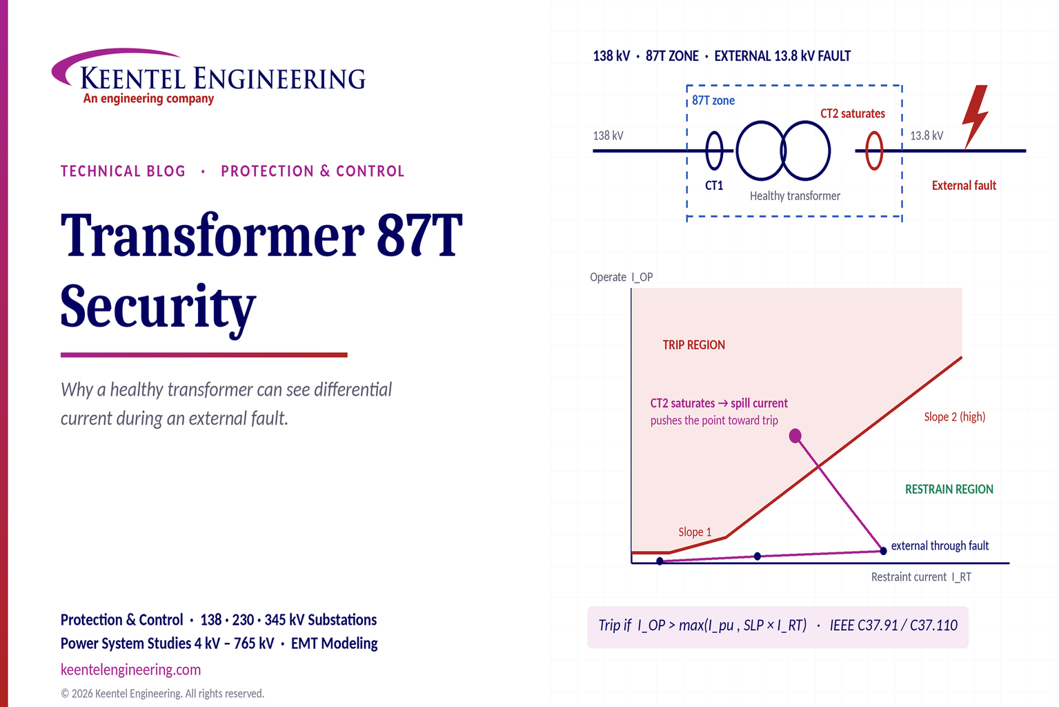
Learn why transformer differential relays detect current during external faults, how CT saturation causes spill current, and how secure 87T protection prevents trips.
By SANDIP R PATEL
•
October 10, 2026
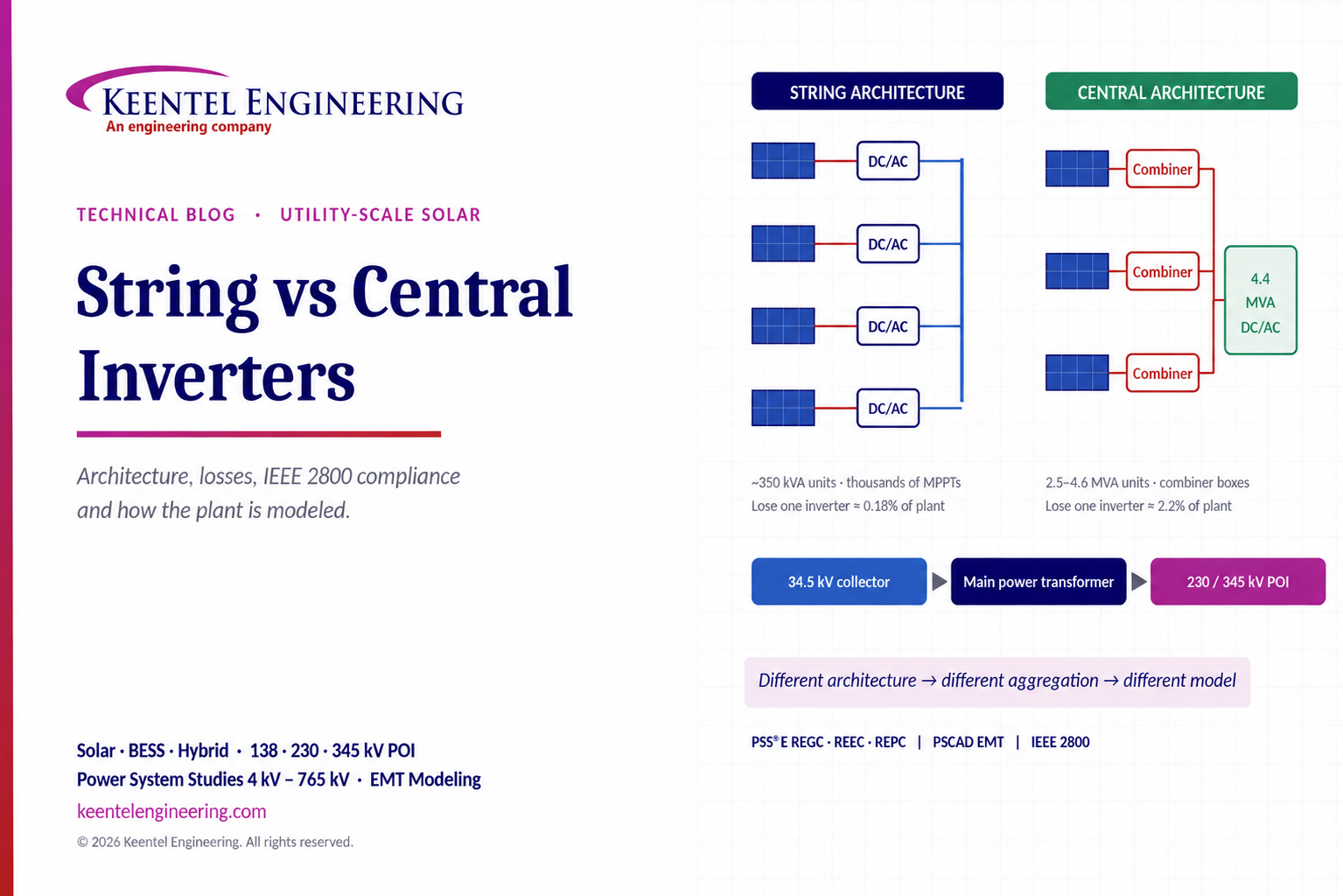
Compare string vs central inverters for utility-scale solar, including efficiency, maintenance, grid compliance, reactive power and interconnection studies.

By SANDIP R PATEL
•
October 3, 2026
Engineering guide to PRC-028 disturbance recording, PRC-029 ride-through and PRC-030 event detection for inverter-based resources.

By SANDIP R PATEL
•
October 3, 2026
A practical guide to SSO classification, SSR, PEDI, Wind-SSCI, EMT analysis, mitigation and protection based on CIGRE TB 909.

By SANDIP R PATEL
•
October 3, 2026
Learn ERCOT generator testing for PFR, MOD-025 and MOD-026/027, including staged tests, capability verification, dynamic models and field testing.

By SANDIP R PATEL
•
October 3, 2026
Learn how PV string I-V curve testing identifies hidden solar performance losses, including soiling, shading, mismatch, degradation, and wiring faults.





