
A Coordinated Electric System Interconnection Review—the utility’s deep-dive on technical and cost impacts of your project.
Challenge: Frequent false tripping using conventional electromechanical relays
Solution: SEL-487E integration with multi-terminal differential protection and dynamic inrush restraint
Result: 90% reduction in false trips, saving over $250,000 in downtime
Reevaluation of IEEE and IEC Substation Design Standards Under Increasing Fault Current Levels
january 21, 2026 | Blog
Technical Perspective for Modern Utility Substations
Bulk power systems across North America are experiencing systematically increasing short-circuit (SC) current levels, driven by stronger transmission interconnections, higher-capacity transformers, utility-scale inverter-based resources, and network meshing. Substation fault duties that historically remained below 63 kA are now frequently approaching 80–100 kA, significantly impacting ieee compliant substation engineering practices and equipment design limits.
Recent developments in
IEC standards news today 2026 highlight the need for updated design approaches to address increasing fault current levels in modern grids.
Drivers of Increasing Fault Currents
The increase in available short-circuit current is primarily attributable to:
- Reduced source impedance due to network reinforcement
- Higher MVA transformer installations at transmission substations
- Parallel transmission paths and regional grid interconnections
- Inverter-based resource (IBR) interconnection without proportional fault current mitigation
- Deployment of fault current reactors that increase X/R ratio while limiting RMS current
While system strength improves reliability metrics, it materially alters equipment duty assumptions embedded in legacy standards.
These changes are driving the evolution of
substation engineering standards to ensure system reliability and safety under extreme fault conditions.
Technical Impacts on Substation Equipment
Bus Structures – Electromechanical and Thermal Stress
Short-circuit currents generate intense electrodynamic forces proportional to I², producing impulsive loading on:
- Rigid and strain bus conductors
- Insulator stacks and post insulators
- Support steel, anchor bolts, and foundations
IEEE Std 605 (1998, 2008) applies static force approximations that assume peak force is instantaneously and uniformly applied. EPRI research demonstrates that these assumptions overestimate peak forces while failing to accurately capture dynamic response, modal behavior, and damping effects.
From a design standpoint, this results in:
- Over-conservative conductor sizing
- Excessive insulator bending moment margins
- Inadequate treatment of foundation load transfer under transient fault conditions
Thermally, IEEE 605 provides limited guidance on conductor expansion but does not address I²t-based cable damage limits, leaving coordination gaps between bus design, protection clearing time, and cable insulation thermal withstand.
Power Transformers – Mechanical Withstand and Thermal Limits
Transformers are uniquely vulnerable to elevated fault currents due to:
- Radial electromagnetic forces causing hoop stress and winding buckling
- Axial forces inducing compression, spacer damage, and clamping system degradation
- Rapid winding temperature rise during through-fault events
IEEE C57 and IEC 60076 standards define short-circuit withstand requirements but do not provide analytical force calculation methodologies. Critically:
- Short-circuit testing is often optional unless explicitly specified
- IEC 60076-5 permits design review in lieu of testing without quantitative validation methods
Field failure statistics cited by EPRI indicate a materially higher failure rate for transformers validated solely by design review, particularly as system fault levels increase.
Operationally, cumulative through-fault exposure and uncontrolled re-energization introduce progressive mechanical degradation that is not adequately addressed in standard maintenance or protection guides.
Switchgear – Interrupting Duty and DC Offset Effects
Modern circuit breakers are affected by increasing fault currents primarily through:
- Increased arcing energy
- Higher DC offset due to elevated X/R ratios
- Longer arcing times and contact erosion
- Steeper transient recovery voltage (TRV) slopes
IEC 62271-100 explicitly addresses higher DC time constants, whereas IEEE C37 standards retain a preferred 45 ms assumption while allowing alternatives. From an asset management perspective, this divergence necessitates system-specific breaker duty verification rather than nameplate-based assumptions.
Implications for IEEE and IEC Standards
Modern utilities must align with
ieee compliant substation engineering methodologies to address limitations in legacy design assumptions.
Identified Gaps
Bus Structures
- Static force assumptions remain dominant in IEEE guidance
- Limited integration of dynamic modeling techniques
- Insufficient foundation-level fault load treatment
Transformers
- Absence of standardized mechanical force calculation procedures
- Optional SC testing creates inconsistent risk profiles
- Limited guidance on cumulative fault damage and controlled energization
Switchgear
- Standards largely adequate but require careful alignment with actual system X/R ratios
Alignment with Keentel Engineering Services
Substation Design & Engineering
Keentel Engineering integrates high-fault-current considerations directly into:
- Bus sizing and support design
- Insulator and foundation load verification
- Transformer specification and procurement support
- Breaker duty and TRV assessment
NERC & Reliability Compliance
Fault current impacts directly intersect with:
- PRC protection system coordination
- TPL system performance studies
- MOD and FAC modeling accuracy
- Asset documentation and
audit defensibility
Power System Studies
Keentel performs:
- High-fidelity short-circuit studies
- EMT-based fault current evaluation
- Protection clearing time optimization
- Transformer thermal and mechanical screening
Engineering Conclusions
Increasing fault currents invalidate many historical substation design assumptions. IEEE and IEC standards remain foundational but must be supplemented by advanced analysis, testing, and periodic reassessment. Utilities and developers that proactively address these issues reduce operational risk, extend asset life, and improve regulatory defensibility.
Keentel Engineering provides the technical depth required to bridge standards, studies, and real-world system behavior.
Keentel Engineering continues to contribute to evolving standards, including research aligned with
keentel engineering ieee std 2842-2022 and advanced fault current modeling.
Frequently Asked Questions (FAQ)
1. What fault current levels are now considered critical for substation design?
In many legacy AIS substations, equipment duty assumptions were commonly bounded by 63 kA symmetrical interrupting / withstand levels. Modern system strengthening and added sources are pushing available fault current toward 80–100 kA in some locations. “Critical” is not a single number; it is the point where one or more elements become duty-limited (bus supports, breaker interrupting rating, transformer through-fault withstand, cable I²t limits, CT saturation, relay operating time). A substation is in a critical range when the calculated maximum available fault current plus modeling uncertainty and growth margin approaches the lowest short-circuit rating among breakers, disconnectors, bus, transformer, or auxiliary conductors.
2. Why do static bus force calculations become inaccurate at high fault levels?
Static methods (as commonly used in rigid bus design) apply a peak electromagnetic force as if it were a constant, quasi-static load. Actual fault forces are impulsive and time-varying, with magnitude tracking asymmetrical current (AC + DC offset) and phase relationships. Bus structures have natural frequencies, damping, and support flexibility; the resulting response depends on dynamic amplification, modal participation, and fault clearing time. As fault current increases, the force scales roughly with I², so any conservatism (or mischaracterization of dynamics) becomes increasingly consequential—driving either overdesign or misalignment with the real failure modes.
3. How do dynamic bus force models improve design accuracy?
Dynamic models treat the bus/support system as a mass–spring–damper structure and apply the time-domain short-circuit forcing function (including DC offset and fault clearing). This approach captures:
- Dynamic amplification (or reduction) relative to static peak
- Sensitivity to protection clearing time and auto-reclosing
- Support stiffness effects (insulator, frames, clamps)
Deflection limits and stress cycles This produces a more defensible estimate of peak deflection, support bending moments, clamp slip risk, and cumulative fatigue—particularly important when assessing uprates or retrofits.
4. Are substation foundations typically designed for fault-induced loads?
Fault-induced electrodynamic loads act on the conductor, transmit through clamps/insulators into steel, and ultimately into anchorages and foundations. Many substation foundation designs rely on general civil criteria and load combinations (wind, seismic, equipment). Explicit short-circuit force transfer to foundations is not consistently treated in electrical standards; it is often handled through company criteria (utility DCMs) and structural codes (e.g., ACI/ASCE) using transient load combinations. Under high fault currents, uplift, shear, and anchor bolt demand can become controlling especially on tall bus pedestals and equipment structures.
5.How does I²t exposure affect substation conductors and cables?
Thermal damage in conductors/cables during faults correlates with the integral of current squared over time (I²t). Cable insulation systems have manufacturer-specific damage curves and maximum permissible I²t for a given insulation type and conductor size. If fault current increases and protection clearing time is unchanged, I²t rises sharply, risking:
Insulation softening/embrittlement
Shield/neutral overheating
Termination and splice damage Mitigation is typically via faster clearing, cable resizing, improved thermal withstand coordination, or fault current reduction.
6.What mechanical failures occur in transformer windings during faults?
Transformer short-circuit events impose large electromagnetic forces:
Radial forces → hoop stress; can cause winding buckling, ovalization, and permanent deformation.
Axial forces → compression/extension; stresses spacers, clamping rings, tie rods; can cause axial displacement and insulation damage. Failure modes include conductor bending past elastic limit (no immediate internal fault) or deformation leading to insulation breakdown and turn-to-turn/turn-to-ground faults
7.Why is transformer short-circuit testing increasingly important?
As fault levels rise, the margin between design capability and actual system duty can shrink. Short-circuit testing validates that the mechanical design (spacers, clamping, winding support, leads) withstands worst-case electrodynamic forces. Industry experience indicates that relying on design review alone can miss subtle weaknesses (tolerances, support stiffness, manufacturing variation). Testing provides evidence of mechanical robustness and can reduce long-term risk of in-service failures.
8. How does cumulative through-fault exposure degrade transformers?
Through-faults create repeating mechanical impulses that can cause:
Progressive insulation compression and wear
Friction-driven displacement
Loosening of clamping systems
Incremental deformation that compounds over time Even when each fault is within thermal limits, repeated mechanical cycling can reduce dielectric margins. Asset management programs increasingly track fault counts and duty (magnitude and duration) to assess remaining mechanical life.
9. What standards govern transformer mechanical withstand capability?
Transformer short-circuit withstand requirements are addressed in IEEE C57 and IEC 60076 families, with IEC 60076-5 focusing on ability to withstand short circuit. However, standards generally specify requirements, categories, and acceptance criteria without providing a unified mechanical force calculation method. Practical engineering often combines standard requirements with manufacturer design documentation, historical test data, and utility-specific procurement clauses.
10. How does controlled energization reduce transformer mechanical stress?
Uncontrolled energization can produce high inrush currents and associated electrodynamic forces comparable to fault forces in some cases. Controlled switching targets optimal closing instants (relative to voltage waveform and residual flux) to minimize inrush magnitude and asymmetry. Benefits include reduced mechanical stress on windings and clamps, lower system voltage disturbances, and improved transformer life-cycle cost—especially relevant when short-circuit margins are tightening.
11. Why do higher X/R ratios increase circuit breaker wear?
Higher X/R ratio increases the DC component time constant, producing a larger and longer-lasting DC offset. This shifts current zero crossings later in time, increasing arcing duration and energy. Longer arcing increases contact erosion, thermal stress, and pressure build-up in interrupters. The breaker may still interrupt successfully but will experience accelerated wear and may require more frequent maintenance or reduced service life.
12. How are DC time constants addressed differently by IEEE and IEC?
IEC practices commonly provide voltage-dependent DC time constants for test duties, reflecting a trend toward higher system X/R. IEEE test procedures historically cite a preferred traditional value (often 45 ms) while permitting alternatives. The practical implication is that engineering teams must verify that the selected breaker’s tested capabilities align with site-specific X/R and asymmetrical duty rather than relying solely on a generic preferred constant.
13. What is TRV and why does it matter at high fault currents?
Transient Recovery Voltage (TRV) is the voltage appearing across breaker contacts immediately after current interruption. High fault currents and short-line faults can produce steep TRV rate-of-rise. If TRV rises too rapidly, it can cause re-ignition or restrike, leading to severe overvoltages and equipment damage. TRV performance depends on system capacitance/inductance, breaker design, and network configuration.
14. When should breaker duty be reassessed?
Breaker duty should be reassessed whenever there are material system changes:
- New transmission lines/transformers
- Generation additions or retirement
- Network reconfiguration/looping
- Reactor installation
Protection setting changes affecting clearing time As a rule, reassess at least every major planning cycle (often 3–5 years) or after any interconnection project that affects short-circuit sources.
15. How do fault current reactors affect protection coordination?
Reactors reduce RMS fault current but increase system reactance, often increasing X/R. That can increase DC offset and arcing time for breakers and can alter relay apparent impedance (distance elements), CT performance, and coordination margins. Coordination studies should evaluate both reduced magnitude and changed waveform characteristics (asymmetry and timing) to ensure protection operates correctly.
16. Can protection settings mitigate mechanical equipment damage?
Yes. Mechanical and thermal stress scales strongly with fault duration. Reducing clearing time reduces:
- Bus dynamic response exposure
- Transformer electrodynamic impulse duration
- Cable I²t energy
Breaker arcing energy However, faster clearing must be balanced with selectivity and system stability constraints. Settings changes should be verified through coordination, CT saturation checks, and system disturbance considerations.
17. How often should short-circuit studies be updated?
Update studies whenever system changes occur and at a minimum on a periodic basis (commonly every 3–5 years). High-growth areas, rapid DER/IBR deployment, or major transmission expansions may require more frequent updates. The update should include model validation and clear documentation of assumptions, base cases, and sensitivity scenarios.
18. What NERC standards are impacted by rising fault currents?
Fault current levels intersect with multiple reliability obligations, especially where protection system performance and study accuracy are required. Common touchpoints include:
- PRC standards (protection coordination, maintenance/testing programs)
- TPL standards (system performance under contingencies)
MOD standards (model data and validation) Even where a specific standard does not mention fault current explicitly, increasing fault duty can alter protection performance and therefore compliance evidence.
19. How does fault current affect PRC compliance documentation?
PRC evidence often relies on defensible settings, coordination, and equipment capability. If fault currents increase, prior coordination assumptions may become invalid (e.g., breaker duty, CT saturation, relay operating times). Documentation should show:
- Updated short-circuit results
- Verification of equipment duty limits
- Updated coordination curves and settings rationale
- Maintenance/test implications for higher duty conditions
20. Are inverter-based resources contributing to higher fault duties?
IBR fault contribution is complex: many inverters provide limited short-circuit current relative to synchronous machines, but system changes associated with IBR interconnection (new transformers, collector tie-ins, network reinforcements) can increase fault levels. Additionally, some systems deploy synchronous condensers or grid-forming resources that can raise available fault current. Proper assessment requires site-specific modeling using the utility’s short-circuit methodology.
21. What studies support transformer procurement decisions?
Procurement decisions should be supported by:
- Short-circuit duty at transformer terminals (max and credible scenarios)
- Through-fault duration exposure based on protection clearing times
- Thermal withstand (I²t) evaluation
- Mechanical withstand validation requirements (testing clauses, similarity criteria)
Inrush/energization strategy assessment Keentel often recommends embedding clear short-circuit performance requirements into specifications and procurement documents.
22. How do EMT simulations improve fault analysis accuracy?
EMT simulation captures time-domain waveform detail including:
- DC offset and asymmetrical current
- Fast transients, TRV interaction, and switching phenomena
- Converter controls and IBR fault response
Protection operation timing in high fidelity EMT is valuable when RMS methods are insufficient—e.g., evaluating controlled switching benefits, TRV concerns, or IBR-dominated networks.
23. Can existing substations be retrofitted for higher fault levels?
Yes, common mitigation pathways include:
- Replacing or uprating breakers/switchgear
- Bus reinforcement (support spacing, insulator strength, clamps)
- Fault current limiting solutions (reactors, FCL technologies)
- Reconfiguring bus arrangements to reduce sources
Adjusting protection to reduce clearing time Retrofit feasibility depends on outage windows, physical clearances, insulation coordination, and cost-benefit.
24. What role does NEC play in conductor and cable protection?
NEC requirements influence conductor sizing, protection coordination, and cable protection practices, especially for auxiliary systems and station service. While substation primary designs often follow utility standards and IEEE/IEC guidance, NEC considerations remain important for thermal withstand, grounding, and equipment protection systems particularly where station cabling and control power circuits are involved.
25. How does Keentel Engineering assess high-fault-current risk?
A defensible assessment typically includes:
- Verified short-circuit model and source data
- Equipment duty comparison (interrupting, withstand, thermal)
- Bus force/deflection screening (static and dynamic as appropriate)
- Cable I²t checks vs clearing time
- Breaker asymmetrical duty and DC time constant evaluation
Protection coordination review and mitigation options Keentel produces documented, audit-ready deliverables and mitigation roadmaps.
26. What data is required to validate breaker interrupting capability?
Required inputs include:
- Maximum symmetrical and asymmetrical fault current at breaker location
- System X/R ratio (or equivalent DC time constant)
- Fault types (3φ, SLG, LL, LLG) and short-line faults where applicable
- Clearing time and duty cycle assumptions
- TRV parameters or network equivalents
Breaker nameplate and tested capabilities Validation should align with applicable IEEE/IEC testing assumptions and local utility criteria.
27. How do utilities balance cost versus conservatism in bus design?
Overly conservative static methods can increase material and structure costs (larger conductors, more robust supports, heavier foundations). A rational approach uses:
- Dynamic modeling where justified
- Sensitivity to clearing time and fault type
- Probabilistic growth margins and credible contingencies
Targeted reinforcement at controlling spans/supports This reduces cost without sacrificing reliability and safety.
28. What operational practices reduce fault-induced asset aging?
Practical practices include:
- Minimizing reclosing into persistent faults
- Ensuring protection clearing times remain optimized
- Tracking fault duty (counts, magnitude, duration)
- Applying controlled energization for critical transformers
Proactive inspection after high-duty faults (bushing checks, dissolved gas analysis, mechanical condition assessments).
29. How do fault currents impact substation lifecycle cost?
Higher fault currents can increase lifecycle cost through:
- Accelerated breaker maintenance and contact replacement
- Increased transformer mechanical aging and risk of forced outage
- Bus/insulator damage and unplanned repairs
Increased need for uprates, retrofits, and replacements A lifecycle approach compares the cost of mitigation (studies, settings, reinforcements) against expected outage and replacement risks.
30. Why is periodic reassessment critical in modern power systems?
Planning and interconnection activity can change short-circuit duty materially within a few years. Without periodic reassessment, substations can drift into duty exceedance conditions where equipment ratings, protection assumptions, and compliance evidence no longer align with actual system risk. Periodic updates ensure designs remain valid, mitigation is planned rather than reactive, and documentation remains defensible for owners, regulators, and NERC audits.

About the Author:
Sonny Patel P.E. EC
IEEE Senior Member
In 1995, Sandip (Sonny) R. Patel earned his Electrical Engineering degree from the University of Illinois, specializing in Electrical Engineering . But degrees don’t build legacies—action does. For three decades, he’s been shaping the future of engineering, not just as a licensed Professional Engineer across multiple states (Florida, California, New York, West Virginia, and Minnesota), but as a doer. A builder. A leader. Not just an engineer. A Licensed Electrical Contractor in Florida with an Unlimited EC license. Not just an executive. The founder and CEO of KEENTEL LLC—where expertise meets execution. Three decades. Multiple states. Endless impact.
Services

Let's Discuss Your Project
Let's book a call to discuss your electrical engineering project that we can help you with.
About the Author:
Sonny Patel P.E. EC
IEEE Senior Member
In 1995, Sandip (Sonny) R. Patel earned his Electrical Engineering degree from the University of Illinois, specializing in Electrical Engineering . But degrees don’t build legacies—action does. For three decades, he’s been shaping the future of engineering, not just as a licensed Professional Engineer across multiple states (Florida, California, New York, West Virginia, and Minnesota), but as a doer. A builder. A leader. Not just an engineer. A Licensed Electrical Contractor in Florida with an Unlimited EC license. Not just an executive. The founder and CEO of KEENTEL LLC—where expertise meets execution. Three decades. Multiple states. Endless impact.
Leave a Comment
Thank you for contacting us.
We will get back to you as soon as possible.
We will get back to you as soon as possible.
Oops, there was an error sending your message.
Please try again later.
Please try again later.
Related Posts
By SANDIP R PATEL
•
July 15, 2026
Learn how PJM markets, governance, stakeholder processes, and interconnection rules shape generation, storage, and large-load projects across North America.
By SANDIP R PATEL
•
July 14, 2026
Learn how AI data centers, cryptocurrency mining, and hydrogen electrolysis impact grid interconnection, EMT modeling, power quality, and system reliability.

By SANDIP R PATEL
•
July 13, 2026
Learn the complete ERCOT BESS interconnection process for TNMP and AEP Texas, including GINR, studies, SGIA, commissioning, fees, and project timelines.
By SANDIP R PATEL
•
July 13, 2026
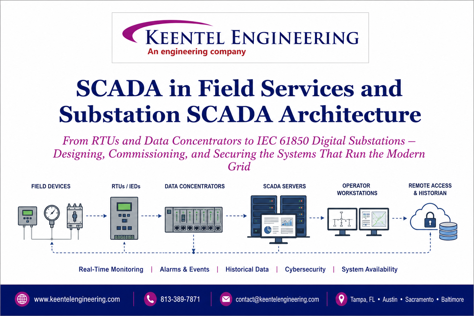
Learn SCADA architecture, IEC 61850, RTUs, IEDs, DNP3, digital substations, commissioning, cybersecurity, and field services for modern power systems.
By SANDIP R PATEL
•
July 13, 2026
Learn how IEEE standards for grounding, protection, power quality, arc flash, and grid interconnection are applied in real engineering projects.
By SANDIP R PATEL
•
July 12, 2026
Complete PRC-028-1 guide for inverter-based resources. 12-chapter technical resource
By SANDIP R PATEL
•
July 11, 2026
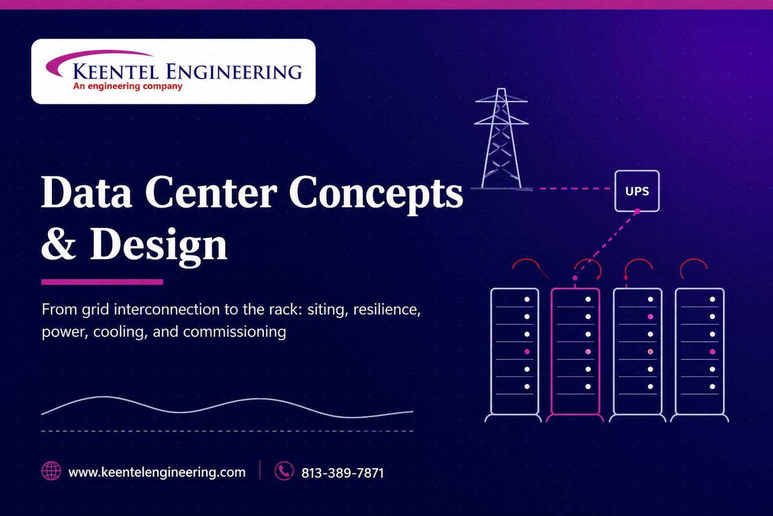
Learn modern data center design, grid interconnection, electrical systems, cooling, commissioning, resilience, and operations for AI-ready facilities.

By SANDIP R PATEL
•
July 11, 2026
Master IEC 61850 SCADA engineering with ACSELERATOR Architect, GOOSE messaging, MMS, SCL files, server models, commissioning, and substation automation.
By SANDIP R PATEL
•
July 11, 2026
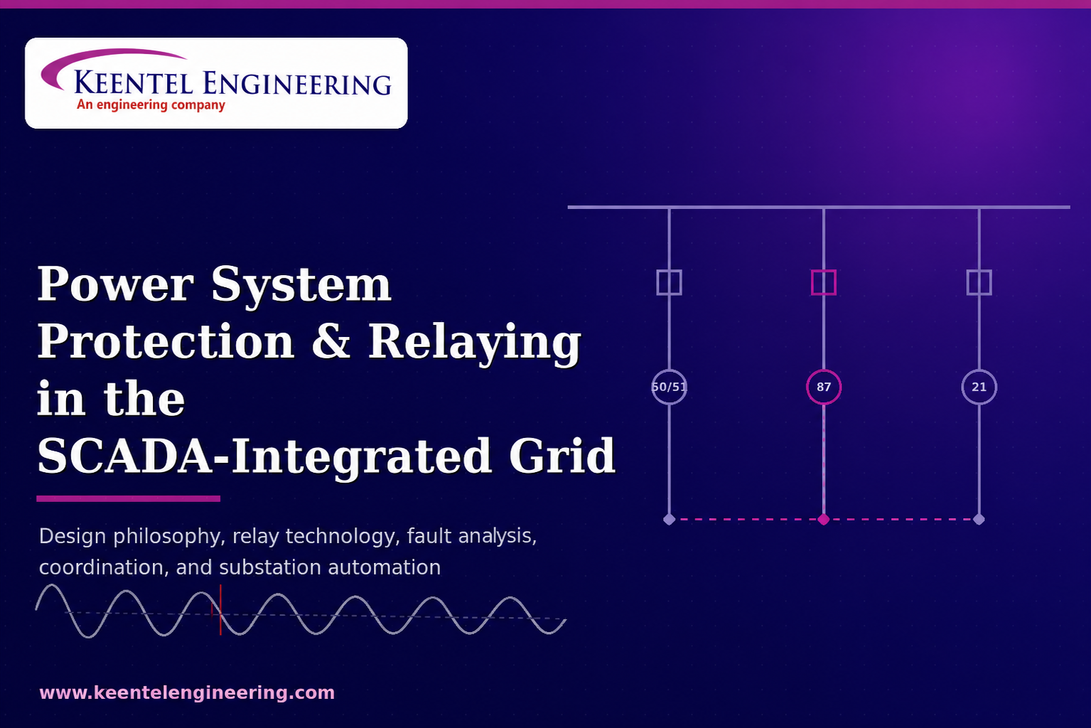
Learn power system protection and relaying, SCADA integration, relay coordination, fault analysis, grounding, and substation protection engineering.


