
A Coordinated Electric System Interconnection Review—the utility’s deep-dive on technical and cost impacts of your project.
Challenge: Frequent false tripping using conventional electromechanical relays
Solution: SEL-487E integration with multi-terminal differential protection and dynamic inrush restraint
Result: 90% reduction in false trips, saving over $250,000 in downtime
ERCOT enforces all of the above through simulation, which means your model is your compliance case. The bar is now high:
- Whole-facility scope. The model must represent everything the IT load, the UPS and power conversion, the cooling plant, the protection and control systems in formats compatible with ERCOT's study platforms (PSS/E, PSCAD, TSAT).
- Real control loops, not approximations. Generic textbook representations are unacceptable. The model must capture the actual inner control behavior of your power electronics.
- Hardware-validated converter models. For electronic loads, the PSCAD model must be benchmarked against actual hardware testing including voltage ride-through and subsynchronous response. A model assembled from standard PSCAD library blocks fails by definition, because a generic block has never been tested against your vendor's hardware. The good news: validation is a hardware-type test, so results for a given converter product are reusable across every facility that uses it.
- Format migration. Facilities that previously submitted the older composite load model (CMLD) format must transition to EPRI's PERC1 format.
- Three checkpoints. Models are reviewed before the stability study begins (no model, no study), before each quarterly stability assessment, and for electronic loads one final time before energization, when you must submit as-built models with a documented comparison against the previously studied data and a sworn attestation that the model matches actual field settings. ERCOT's review takes 10 business days, extendable by 20 put it on your critical path.
- A living obligation. Change your technology, controls, or relay settings in a way that affects ride-through including converting a crypto mining site to an AI data center — and you've triggered a new interconnection study, even if your megawatts don't change.
| Parameter | Detail |
|---|---|
| System | 230 kV / 138 kV transmission corridors, wind and wet-snow icing exposure |
| Data basis | 15 years of minute-resolution forced-outage records + regional weather observations |
| Core methods | Event grouping, MVA performance curves, time-to-95%-restore, area outage rate curves, fragility modeling, rerun-history benefits, exceedance and log-domain risk metrics |
| Headline result | ≈85% of maximum resilience benefit at 60% of original capital; worst-event restoration window cut from 11 days to 5 in rerun-history terms |
| Decision supported | Capital portfolio selection; resilience plan filing; post-investment verification framework |
| System / Topic | Governing Standard(s) | What It Controls |
|---|---|---|
| Overall plant electrical distribution | IEEE 141 (Red Book); IEEE 666 | Distribution architecture, voltage selection, design of generating station auxiliary service systems |
| Power system studies | IEEE 399 (Brown Book); IEEE 551 | Load flow, symmetrical/asymmetrical short circuit, motor starting methodologies down to the lowest LV panelboard |
| Protection & coordination | IEEE 242 (Buff Book); IEEE 3004.5; IEEE C37 series | Generator relaying (21, 59N, 87G), time-current coordination, selective clearing between LV and MV tiers |
| GSU / UAT / SST transformers | IEEE C57.12.00 and C57 family | Transformer ratings, impedance, testing, loading |
| HV switchyard breakers | IEEE C37.06 | AC high-voltage circuit breaker preferred ratings |
| MV switchgear (13.8 kV) | IEEE C37.20.2; IEEE C37.20.7 | Metal-clad construction, compartmentalization, vacuum breakers; arc-resistant design with plenum venting |
| MV cable | UL 1072; ICEA S-93-639 (NEMA WC 74) | Type MV-105 shielded cable, 133% insulation level for HRG systems |
| LV switchgear (480 V) | IEEE C37.13; UL 1558 | Metal-enclosed LV power circuit breaker switchgear to 635 V, draw-out ACBs with electronic trip units |
| Motor control centers | UL 845; NEMA ICS 18 | LV-MCC construction, MCCB/MCP protection for motors under ~200 HP |
| Motors | NEMA MG-1 | Motor performance, starting characteristics, service factors |
| DC & battery systems | IEEE 485; IEEE 946 | Lead-acid battery sizing (125/250 VDC), DC auxiliary system design |
| Grounding | IEEE 80; IEEE 142 (Green Book) | Ground grid step/touch potential limits; system grounding including high-resistance grounding |
| Lightning protection | IEEE 998 | Direct-stroke shielding of switchyard and outdoor generator structures |
| Arc flash & electrical safety | IEEE 1584; NFPA 70E | Incident energy calculation; worker safety boundaries and PPE |
| Fire protection | NFPA 850 | Fire protection and risk management for combustion turbine generating plants |
| Installation code | NEC (NFPA 70); NESC | Wiring methods inside the plant fence; overhead/outdoor clearances at the switchyard |
| Interconnection & compliance | FERC LGIP; NERC MOD-025/026/027, PRC-019/024/029, FAC-008 | Interconnection process, model validation, protection/ride-through coordination, facility ratings |
| IFC / Construction Deliverable | Purpose |
|---|---|
| Stamped IFC packages | Legal basis for construction; P.E. responsible charge |
| Final relay settings & TCCs | Protection as-installed matches the coordination study |
| Calculation archive | Owner records; NERC audit evidence trail |
| Commissioning procedures | Safe, sequenced energization; MOD field testing |
| Construction support | RFIs, field changes, FAT/SAT witness |
| As-builts & model handoff | Operating baseline; future study currency |
| Metric | Outcome |
|---|---|
| Defects found pre-occupancy | Three topology defects and one settings-mismatch family corrected before load migration; the shared-switchboard defect alone would have invalidated the concurrently-maintainable claim on day one |
| IST findings | Fourteen additional discrepancies surfaced under scenario testing (control logic, alarm mapping, one generator sequencing fault) — all closed before handover instead of during operations |
| Black-building test | Passed on second execution; the first attempt exposed the generator sequencing fault under true block load, exactly the failure the compressed plan would never have found |
| Handover quality | Operations team certified on the actual failure scenarios; corrected EOPs and settings documentation delivered as controlled documents |
| Business outcome | Occupancy proceeded three weeks behind the original date — against an independent estimate that the uncorrected sequencing fault carried a high probability of a full facility outage within the first year |
Part 2 — Frequently Asked Questions: Large Load Interconnection
An electric grid must remain in continuous balance — generation onto the grid must equal consumption from it at every instant. PJM achieves this balance, and prices it, through a layered market architecture. Each layer operates on a different time horizon, and each one touches project economics differently.
| Domain | Key Standards / Codes | What They Govern |
|---|---|---|
| Fire safety | NFPA 855; UL 9540 / UL 9540A | Installation requirements, separation, gas management; system safety listing and thermal-runaway fire testing |
| Grid interconnection | IEEE 1547 (distribution); IEEE 2800 (transmission IBRs) | Ride-through, reactive capability, power quality, and performance at the point of interconnection |
| Power quality | IEEE 519 | Harmonic distortion limits at the PCC |
| Protection & grounding | IEEE 80 / 81 / 142; C37 series | Grounding system design and testing; protective relaying |
| Reliability compliance | NERC standards (incl. PRC ride-through requirements) | Registered-entity obligations for grid-connected storage |
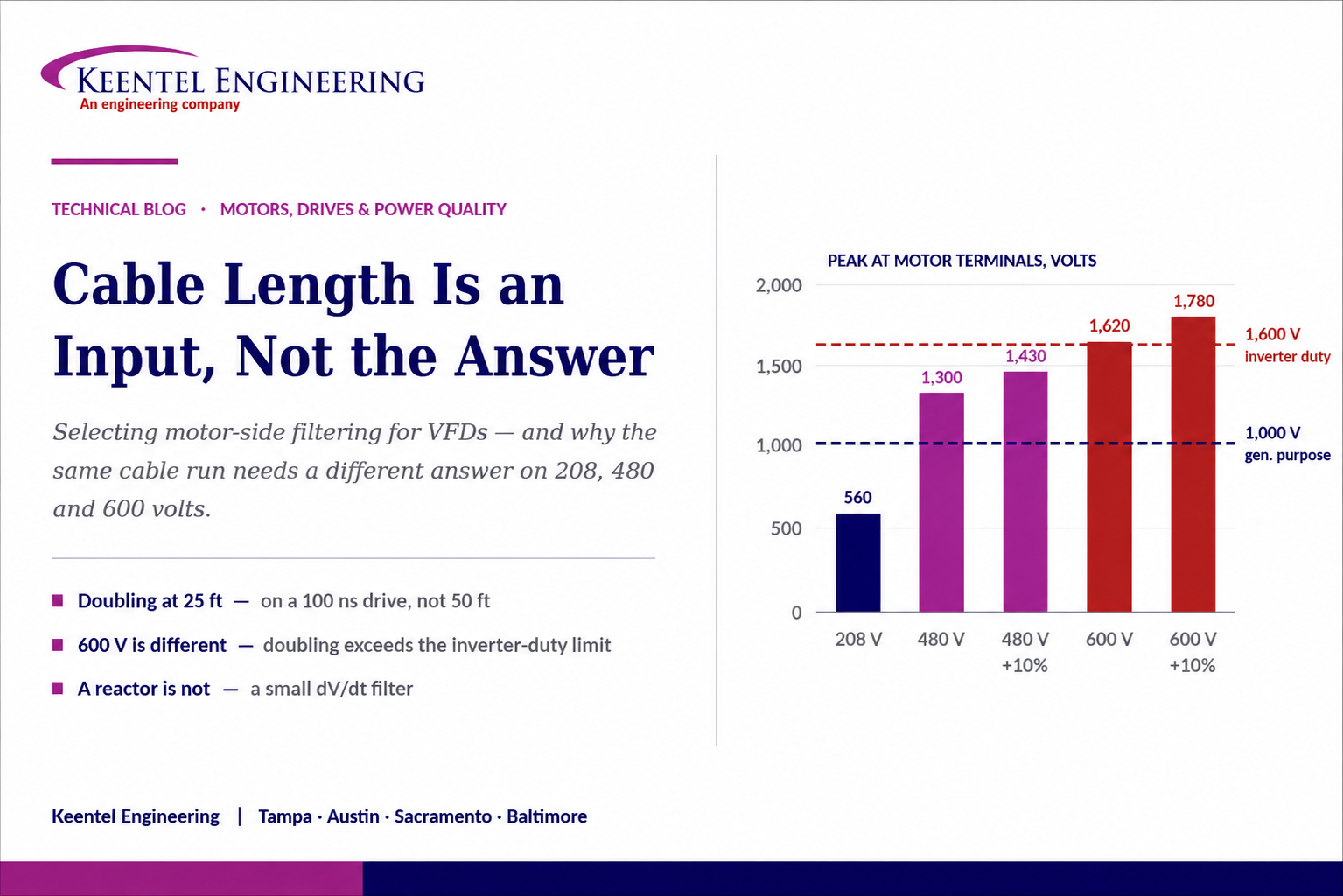
Cable Length Is an Input, Not the Answer
Aug 31, 2026 | Blog
Three Numbers That Decide Whether a Fault Is an Outage or an Incident — Why Only One of Them Is a Rating, Why It Moves, and Why the Equipment Never Tells You
1. Executive Summary
"How long is the motor cable?" is usually the first question asked when deciding whether a variable frequency drive application needs no filter, an output reactor, a dV/dt filter, or a sine-wave filter. It is a reasonable first question. It is not sufficient to answer with, and treating it as sufficient is a recurring source of premature motor winding failures, nuisance drive trips, and expensive retrofits.
The problem the filtering addresses is a transmission line problem. A drive produces voltage pulses with rise times measured in tens or hundreds of nanoseconds. The motor cable has a characteristic impedance of roughly 80 to 100 ohms; the motor presents a far higher surge impedance. That mismatch reflects the incoming pulse back down the cable. If the round trip takes longer than the pulse takes to rise, the reflected pulse arrives while the incident pulse is still rising, and the two add. The voltage at the motor terminals approaches twice the DC bus voltage, and with ringing and multiple reflections it can exceed that.
Cable length matters because it sets the round-trip time. But whether the resulting peak is a problem depends on the DC bus voltage, which depends on the system voltage class; on the drive’s rise time, which varies by drive family and device technology; on the motor’s insulation withstand, which is a specification with a number attached; on the motor’s frame size, which sets the reflection coefficient; and on cable construction and system topology. A 208-volt system, a 480-volt system, and a 600-volt system with identical cable runs are not the same problem, and they do not have the same answer.
The quantitative core of this paper is two calculations. The first is the critical cable length above which full voltage doubling occurs, which for a modern drive can be as short as twenty-five feet — well inside the range where most rules of thumb say no filter is required. The second is the peak voltage that results, compared against the motor’s published withstand. On 480 volts with an inverter-duty motor, doubling is survivable. On 600 volts it is not, and no amount of cable-length reasoning changes that.
This paper works through the physics, the numbers, what each filtering device actually does and does not do, the constraint that overrides all of it — the drive manufacturer’s published limits — and a decision framework that uses cable length as one input among several. It includes three illustrative case scenarios, a verification protocol, and a twenty-question FAQ.
The conversion, since the common rules of thumb are stated in metres\
15 m is approximately 50 feet. 75 m is approximately 250 feet. 180 m is approximately 590 feet.
Those numbers appear throughout the industry as if they were universal thresholds. They are not thresholds. They are one manufacturer’s guidance for one voltage class, one drive family, one switching frequency, and one class of motor insulation, repeated until it looked like a law.
2. What the Rule of Thumb Is Encoding
Length-based selection guidance is not wrong so much as compressed. Every such rule silently assumes values for the variables that actually govern the outcome. Written out, a typical rule assumes a 480-volt system, a diode front end producing a DC bus around 650 volts, a drive with a rise time in the low hundreds of nanoseconds, a switching frequency in the low kilohertz, shielded three-conductor drive cable, a motor built to the definite-purpose inverter-fed standard, a single motor on a single cable, and an ordinary indoor installation.
Change any one of those and the thresholds move. Some of the changes move them by a factor of two or more.
- System voltage. The DC bus scales with the line voltage, so the peak at the motor terminals scales with it. This is the largest single effect and it is the one most often ignored.
- Drive family and rise time. Faster switching devices produce shorter rise times, which shortens the critical cable length. Newer is worse, not better, for this particular problem.
- Switching frequency. Higher switching frequency does not change the peak of a single pulse, but it increases the number of pulses per second, the cable charging current, the thermal duty on the insulation, and the probability of partial discharge.
- Cable construction and capacitance. Shielded cable has substantially higher capacitance to ground than unshielded, which increases charging current and common-mode current. Characteristic impedance varies with construction, which changes the reflection coefficient.
- Motor insulation system. A general-purpose motor and a definite-purpose inverter-fed motor have different published withstand limits, and the difference between them is the difference between a filter being optional and being mandatory.
- Motor size. Smaller motors have higher surge impedance and therefore a higher reflection coefficient. A small motor on a short cable can see a worse peak than a large motor on a long one.
- Parallel conductors and multiple motors. Parallel runs multiply capacitance. Multiple motors on one drive create impedance discontinuities at every tee, producing reflections from points that are not the motor terminals.
- The manufacturer’s published limits. These are binding regardless of what any general rule says, and they differ between drive models, between cable types, and between filtered and unfiltered configurations.
3. The Physics: Reflected Wave on a Transmission Line
At the timescale of a drive’s switching edge, a motor cable is not a lumped impedance. It is a transmission line, and the standard transmission line results apply.
3.1 The Reflection
When a voltage step travelling down a line reaches a termination whose impedance differs from the line’s characteristic impedance, part of the step reflects. The reflection coefficient is the difference between the load and line impedances divided by their sum. Typical drive cable has a characteristic impedance in the range of 80 to 100 ohms. A motor presents a surge impedance that is far higher — hundreds to thousands of ohms depending on frame size — so the coefficient approaches positive one and the reflected step is nearly the full magnitude of the incident step, with the same polarity.
The reflected step adds to the incident step at the motor terminals. The result approaches twice the DC bus voltage. The reflection then travels back to the drive, reflects again from the drive’s low impedance with opposite polarity, and returns — producing the characteristic ringing seen on any oscilloscope trace at a motor terminal. Under some combinations of cable length, switching frequency, and pulse pattern, successive pulses can superimpose and the peak can exceed twice the bus voltage.
3.2 Why Rise Time Sets the Threshold
The doubling only fully develops if the reflected wave returns while the incident pulse is still rising. If the pulse has already reached its final value before the reflection arrives, the reflection adds to a steady value and produces a smaller relative overshoot. The transition point is where the round-trip propagation time equals the rise time.
Propagation velocity in typical power cable is roughly half the speed of light, on the order of 490 feet per microsecond, varying with insulation material and construction between about 400 and 590 feet per microsecond. The critical length is therefore the propagation velocity multiplied by the rise time, divided by two.
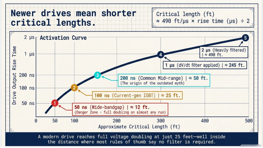
Critical length (ft) ≈ 490 ft/μs × rise time (μs) ÷ 2
4. Critical Cable Length
Working the calculation for the rise times encountered in practice produces the following. Treat these as approximate — propagation velocity varies by cable type by roughly twenty percent either way, and manufacturers state rise time differently.
| Drive output rise time | Approximate critical length | Typical of | What it means |
|---|---|---|---|
| 50 ns | ≈ 12 ft | Fast wide-bandgap output stages | Full doubling occurs on almost any practical cable run, including short in-room installations |
| 100 ns | ≈ 25 ft | Current-generation IGBT drives | Full doubling well below the 50 ft figure most rules of thumb use as the no-filter threshold |
| 200 ns | ≈ 50 ft | Common mid-range drives | The origin of the familiar 50 ft / 15 m guidance — valid only for this rise time |
| 400 ns | ≈ 98 ft | Older or larger-frame drives | Longer runs tolerated before full doubling develops |
| 1 µs | ≈ 245 ft | Output with a dV/dt filter fitted | One of the two things a dV/dt filter buys you |
| 2 µs | ≈ 490 ft | Heavily filtered output | The rise time the general-purpose motor standard assumes |
The most useful single takeaway
A modern drive with a 100 nanosecond rise time reaches full voltage doubling at roughly 25 feet of cable.
That is inside the panel-to-motor distance in a great many installations, and it is half the length at which the most widely repeated rule of thumb says no filter is needed. Whether that doubling matters is a separate question — answered in the next section — but the doubling itself is not avoided by keeping the run short.
5. Voltage Class Changes the Answer Completely
Doubling only matters relative to what the motor can withstand. The peak at the motor terminals is approximately twice the DC bus voltage, and the DC bus for a conventional diode front end is approximately 1.35 times the line-to-line RMS voltage. Working that through for the common North American voltage classes, and comparing against the widely used motor insulation limits, produces the table that should be the starting point of every one of these conversations.
| System voltage | Approx. DC bus | Approx. peak at motor (2×) | General-purpose motor limit | Inverter-duty motor limit | Verdict |
|---|---|---|---|---|---|
| 208 V | ≈ 280 V | ≈ 560 V | 1,000 V | 1,600 V | Comfortable margin against both. Reflected wave is rarely the governing concern; charging current and common-mode effects still are |
| 240 V | ≈ 325 V | ≈ 650 V | 1,000 V | 1,600 V | Comfortable margin against both |
| 480 V | ≈ 650 V | ≈ 1,300 V | 1,000 V | 1,600 V | Exceeds the general-purpose limit. Within the inverter-duty limit, with roughly 20 percent margin before ringing and high-line conditions are considered |
| 480 V at +10% line | ≈ 715 V | ≈ 1,430 V | 1,000 V | 1,600 V | Margin against the inverter-duty limit narrows to about 10 percent. Ringing overshoot can consume it |
| 480 V with active front end | ≈ 750 V | ≈ 1,500 V | 1,000 V | 1,600 V | A regenerative or active front end boosts and regulates the bus higher than a diode bridge. Margin is minimal |
| 600 V | ≈ 810 V | ≈ 1,620 V | 1,000 V | 1,600 V | Exceeds the inverter-duty limit at nominal line voltage, before ringing is considered. Filtering or a higher insulation class is required, not optional |
| 600 V at +10% line | ≈ 890 V | ≈ 1,780 V | 1,000 V | 1,600 V | Substantially over. This is the case that produces repeat winding failures on installations that followed a length-based rule |
Three conclusions follow directly, and none of them can be reached from cable length alone.
- On 208 and 240 volt systems, reflected wave overvoltage is rarely the governing design constraint. Long cables on those systems still raise charging current and common-mode issues, but the motor insulation is not the thing under threat.
- On 480 volt systems, the answer depends almost entirely on which motor is installed. With a definite-purpose inverter-fed motor there is workable margin. With a general-purpose motor there is not, at any cable length past the critical length.
- On 600 volt systems, doubling exceeds the standard inverter-duty limit at nominal voltage. Filtering that reduces the peak — not merely one that slows the edge — is required, and a rule of thumb that permits an unfiltered run of any length is unsafe for the motor.
6. Motor Insulation Is a Specification, Not an Assumption
The two numbers in the table above come from the motor standard, and they are worth stating precisely because the distinction between them decides projects.
The general-purpose section of the standard applies to motors not specifically built for inverter service and, for systems at or below 600 volts, sets a peak voltage limit of 1,000 volts with a rise time of at least 2 microseconds. The definite-purpose inverter-fed section applies to motors built for drive service and raises the limit to 1,600 volts peak with a rise time as short as 0.1 microseconds. The international equivalents divide insulation into types with corresponding stress categories and add partial discharge qualification for the more demanding classes.
Two practical consequences follow.
- A retrofit that puts a drive in front of an existing general-purpose motor is the highest-risk configuration in this entire subject. The motor was never qualified for the stress, the limit is 1,000 volts, and a 480-volt drive past the critical length delivers about 1,300. Failures appear as turn-to-turn shorts in the first coil of the winding — the coil that sees the steepest fraction of the incoming pulse.
- Inverter duty is a claim that should be verified against the motor datasheet rather than inferred from a nameplate marking or a vendor’s description. The relevant data are the peak withstand voltage and the qualifying rise time. If the motor supplier cannot produce them, the motor should be treated as general purpose for design purposes.
7. Motor Size, Cable, and Topology
7.1 Smaller Motors Are Worse
The reflection coefficient depends on the ratio of motor surge impedance to cable characteristic impedance. Small motors have higher surge impedance, so the coefficient is closer to unity and the overshoot is larger. Large motors present a lower surge impedance, so some of the incident energy is absorbed rather than reflected. The consequence is counterintuitive and important: a 5 horsepower motor on 60 feet of cable can see a higher terminal peak than a 200 horsepower motor on 300 feet. Selection rules based on cable length alone implicitly assume a motor size, and applications with many small motors on long runs — common in HVAC and water treatment — are the ones most often mis-specified.
7.2 Cable Construction
Cable choice affects three separate quantities. Characteristic impedance sets the reflection coefficient. Capacitance to ground sets the charging current the drive must supply and the common-mode current that returns through the grounding system. Shield construction and termination determine how much of that common-mode current returns on an intended path rather than through bearings, conduit, or structural steel.
Shielded, symmetrical drive cable with a low-impedance ground path and a full-circumference termination at both ends is the correct default. It has higher capacitance than unshielded cable, which is a real cost in charging current on long runs, and it is still the right answer in nearly every case because of what it does for common-mode return and radiated emissions.
7.3 Multiple Motors and Parallel Runs
Parallel conductors per phase multiply the capacitance seen by the drive. Multiple motors fed from one drive introduce an impedance discontinuity at each junction, producing reflections from points other than the motor terminals and making the resulting waveform difficult to predict analytically. For multi-motor applications, the total conductor length is the sum of all branches, not the longest branch, and manufacturer limits are usually stated on that basis.
Any discontinuity in the run — a junction box, a disconnect, a change of conductor size, a transition between cable types — is a partial reflection point. Installations that appear to violate the physics usually have one of these somewhere in the run.
8. The Other Failure Mode: Common-Mode Current
Reflected wave overvoltage attacks the winding insulation. A second, entirely separate mechanism attacks the bearings, and a filter selected for the first does not necessarily address the second.
Pulse width modulation produces a common-mode voltage — the average of the three phase voltages relative to ground — that steps in increments as the inverter switches. That voltage couples capacitively from the stator winding to the rotor, producing a shaft voltage. When the shaft voltage exceeds the dielectric strength of the lubricant film, it discharges through the bearing, producing localised melting, fluting, and eventual failure. On larger frames a second mechanism appears: high-frequency circulating current driven around the shaft, frame, and bearings by the changing common-mode flux.
Cable length matters here too, because longer cables with higher capacitance carry more common-mode current, and because the quality of the shield ground return determines whether that current has a low-impedance path back to the drive or finds one through the machine. The mitigations are different from the reflected-wave mitigations: shaft grounding, insulated bearings on the non-drive end for larger frames, symmetrical shielded cable with proper terminations, common-mode chokes at the drive output, and attention to the bonding of conduit, cable tray, and machine frame.
A distinction worth keeping straight
An output reactor or a dV/dt filter addresses differential-mode stress at the winding. It does comparatively little for common-mode current and bearing stress.
A sine-wave filter with a properly grounded neutral connection can substantially reduce both, which is one of its less-advertised advantages. A specification that lists a filter but says nothing about shaft grounding or cable shielding has addressed one failure mode and left the other.
9. What Each Device Actually Does
| Option | What it does | What it does not do | Costs and constraints |
|---|---|---|---|
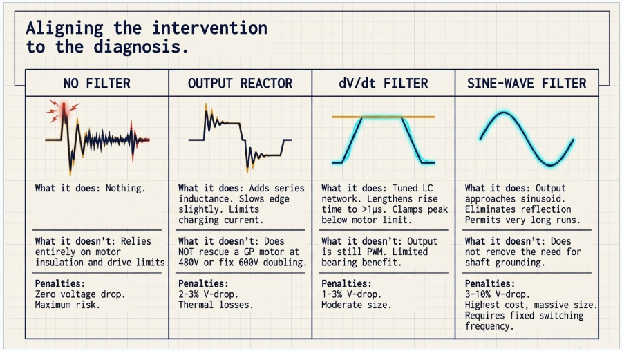
| No filter | Nothing. Relies on the motor insulation withstanding the stress, and on the drive tolerating the cable charging current | Provides no margin for line voltage excursions, ringing, future motor replacement with a lesser insulation class, or added cable during modifications | Only defensible where the calculated peak sits comfortably inside the motor limit and inside the drive’s published cable length — both verified, not assumed |
| Output reactor | Adds series inductance. Slows the rate of rise moderately, limits charging current, reduces drive overcurrent nuisance trips, and adds damping | Does not eliminate the reflection. Reduces the peak only modestly. Does not make a general-purpose motor safe at 480 V past the critical length, and does not solve 600 V doubling | Voltage drop on the order of two to three percent at full load, with the corresponding loss of available motor voltage and low-speed torque. Losses and heat in the enclosure |
| dV/dt filter | A tuned inductive-capacitive network, usually damped, that lengthens the rise time to roughly a microsecond or more and clamps the peak below the motor limit | Does not produce a sinusoidal output. The motor still sees pulse width modulation, just with gentler edges. Limited benefit for common-mode and bearing stress | Moderate cost and size. Voltage drop typically one to three percent. Effective over a defined cable length range that must be checked against the specific product |
| Sine-wave filter | A low-pass network with a corner frequency well above fundamental and well below switching frequency. Output approaches a sinusoid. Eliminates reflected wave entirely and permits very long runs and standard motors and cable | Does not remove the need to think about grounding and bonding. Does not suit high-dynamic applications | Highest cost, size and losses. Voltage drop commonly three to ten percent. Requires a fixed, adequate switching frequency — a drive that reduces switching frequency automatically on temperature or load can detune the filter. Often restricts the drive to open-loop volt-per-hertz control and limits maximum output frequency |
10. The Constraint Nobody Reads
Above every general principle in this paper sits a specific one: the drive manufacturer publishes maximum motor cable lengths for each drive model, and those limits are binding regardless of what any rule of thumb or calculation suggests.
Those published limits are typically stated separately for shielded and unshielded cable, sometimes vary with switching frequency, sometimes vary with drive frame size, and are usually stated both with and without each filtering option the manufacturer offers. They exist for two reasons that are frequently conflated. One is motor insulation protection. The other is the drive’s own capability: the capacitive charging current of a long cable flows through the output stage, and beyond a certain length the drive cannot supply it without nuisance overcurrent tripping or thermal derating. A filter selected to protect the motor does not necessarily bring the installation inside the drive’s charging current limit, and vice versa.
Exceeding a published limit also has a commercial dimension. Warranty claims on motors and drives in these applications routinely turn on whether the installation was within the published cable length and whether the specified filtering was installed. The engineering record showing the calculation and the selection is the document that resolves those disputes.
11. A Decision Framework
Cable length enters at step three, which is roughly where it belongs.
- Establish the DC bus voltage. Start from the system voltage class, apply the expected line voltage tolerance, and account for the front-end topology. An active or regenerative front end regulates the bus above what a diode bridge produces, and that difference is directly a difference in motor terminal peak.
- Obtain the drive’s actual output rise time and switching frequency from the manufacturer, not from a general assumption about the technology. Establish whether the drive reduces switching frequency automatically under thermal or load conditions, because a filter selection can depend on it not doing so.
- Establish the routed cable length — as installed, following the actual raceway path, including spare length in pull boxes — and compute the critical length. For multiple motors, sum all branches.
- Establish the motor’s insulation withstand from its datasheet: peak voltage and qualifying rise time. Treat any motor whose supplier cannot produce those numbers as general purpose.
- Compute the expected peak at the motor terminals and compare it against the withstand, with margin for ringing overshoot and high-line conditions. Decide how much margin the application warrants — a critical process motor in a remote location warrants more than an accessible fan.
- Check the drive’s published cable length limit for the actual cable type and switching frequency, both unfiltered and with each candidate filter. This can override the result of step five in either direction.
- Assess common-mode and bearing exposure separately: motor frame size, shaft grounding provisions, bearing insulation, cable shield construction and termination, and the quality of the bonding path back to the drive.
- Assess the application constraints that restrict filter choice: required control mode, dynamic response, maximum output frequency, acceptable voltage drop, available panel space, ambient temperature, and whether the drive will run at a fixed switching frequency.
- Select the least intervention that satisfies every constraint above, and document why each of the alternatives was rejected. That documentation is what makes the selection defensible later.
- Verify by measurement at commissioning, and record the result.
12. Verifying by Measurement
The calculation predicts; the measurement confirms. Verification at the motor terminals is inexpensive relative to a winding failure and is the only way to close the loop on assumptions about rise time, cable characteristics, and installation quality.
- Measure line-to-line at the motor terminal box, not at the drive output. The drive terminals are the one place in the system where the problem is invisible.
- Use a high-voltage differential probe and an oscilloscope with bandwidth adequate for the edge being measured — a hundred megahertz or better for a hundred-nanosecond edge. Insufficient bandwidth understates both the peak and the rise time, which produces a comfortable and wrong answer.
- Keep probe ground leads extremely short. Ground lead inductance produces ringing that is an artefact of the measurement rather than a property of the system, and it is routinely mistaken for the real thing.
- Record peak voltage, rise time, and ringing frequency, and compare the peak against the motor’s published withstand rather than against a general expectation.
- Measure across the operating range, including low speed where pulse patterns are narrowest, and at the operating temperature where the drive may have reduced its switching frequency.
- Retain the measurement with the commissioning record. It is the evidence that resolves a warranty dispute and the baseline against which a future modification is judged.
13. Case Studies
The following scenarios are composite and illustrative. They are constructed from patterns that recur across industrial and commercial installations to show how the failure develops and how it is diagnosed. They do not describe any specific client, site, project, manufacturer, or product.
13.1 Case A — A 600 Volt System Inside the Rule of Thumb
Situation. A process plant on a 600 volt system installed several drives feeding motors at roughly 250 feet of routed cable. The design applied a widely circulated selection rule and, at that length, specified output reactors. The motors were purchased as inverter duty. Within eighteen months, three motors failed with turn-to-turn shorts in the first coils.
What the analysis found. On a 600 volt system the DC bus sits near 810 volts, and full reflection at that length produced a terminal peak on the order of 1,600 volts at nominal line voltage, higher during high-line periods. That is at or above the standard inverter-duty withstand before ringing overshoot is counted. The output reactors had slowed the edge and reduced nuisance drive trips, and they had reduced the peak only slightly — which is what an output reactor does. Terminal measurements on a surviving drive confirmed peaks consistent with the calculation.
Exposure. Every motor on the system was operating above its qualified insulation stress continuously. Failures were arriving on a schedule set by insulation ageing, not by any single event, and the remaining motors were on the same trajectory.
Remedy. dV/dt filters sized for the cable length and switching frequency were fitted, lengthening the rise time and clamping the peak well below the motor limit. Post-installation measurement at the motor terminals confirmed the result. A motor insulation upgrade was evaluated as an alternative and rejected on cost and lead time.
Lesson. The rule of thumb encoded a 480 volt assumption. On 600 volts, doubling exceeds the standard inverter-duty limit at nominal line voltage, so a device that only slows the edge is not sufficient. Voltage class has to enter the decision before cable length does.
13.2 Case B — A Short Run and a General-Purpose Motor
Situation. An energy retrofit added variable frequency drives to existing 480 volt fan and pump motors in a commercial building. Cable runs were short — typically 40 to 70 feet — and the project applied a no-filter-under-50-feet rule, with reactors on the few longer runs. Motor failures began appearing within the first year, concentrated on the smaller frames.
What the analysis found. Two factors compounded. The drives had a rise time near 100 nanoseconds, which places the critical length around 25 feet — half the threshold the rule used — so full doubling was occurring on essentially every run including the short ones. And the existing motors were general purpose, not inverter duty, with a 1,000 volt peak withstand against a calculated terminal peak near 1,300 volts. The smaller frames failed first, consistent with their higher surge impedance and correspondingly higher reflection coefficient.
Exposure. The entire retrofitted motor population was operating above its qualified stress. Because the motors were original equipment and had been in service for years, the insulation had no remaining margin to absorb the new duty.
Remedy. dV/dt filters were fitted at the drives, which was substantially cheaper than replacing the motor population and required no mechanical work. Shaft grounding was added on the larger frames, and cable was reterminated with proper shield connections where the original installation had pigtailed the shield.
Lesson. Retrofitting drives onto existing general-purpose motors is the highest-risk configuration in this subject, and a short cable run does not protect it. The relevant threshold is the critical length for the actual drive, and the relevant limit is the motor’s actual qualification — which for an existing motor is almost never the inverter-duty number.
13.3 Case C — A Sine-Wave Filter That Was Detuned by the Drive
Situation. A remote pumping installation required roughly 1,200 feet of cable between the drive enclosure and the motor. A sine-wave filter was correctly identified as the appropriate solution and installed. The system performed acceptably through commissioning in mild weather. During the first hot season the drive began tripping, filter components ran hot, and output waveform quality degraded.
What the analysis found. The drive was configured to reduce its switching frequency automatically as heatsink temperature rose — a normal protective behaviour. At the reduced frequency the switching content moved toward the filter’s corner frequency, so the filter no longer attenuated it and began to see substantial current at frequencies it was not sized for. Separately, the installation used parallel conductors per phase for ampacity, roughly doubling the capacitance the filter and drive had to handle relative to the single-run assumption used in the original selection.
Exposure. Filter capacitor and reactor thermal stress, drive nuisance tripping during the hottest and most operationally critical period, and progressive component degradation that would have ended in filter failure.
Remedy. The drive was reconfigured to hold a fixed switching frequency at or above the filter’s design point, with the resulting thermal derating accepted and the enclosure cooling upgraded to support it. The filter was re-evaluated against the actual parallel-conductor capacitance and resized. Operation was re-verified at summer ambient rather than at commissioning conditions.
Lesson.
A sine-wave filter is a tuned circuit whose design assumes a switching frequency. Any drive behaviour that changes that frequency — automatic thermal derating, load-dependent modulation, an energy-saving mode — invalidates the tuning. Verify the drive will hold the assumed frequency across the full ambient and load range, and verify the cable capacitance actually installed rather than the one assumed
14. Reading the Chart Correctly
The four-tier selection chart is a useful teaching device and a poor specification. Four corrections make it usable.
The thresholds are conditional, not universal
Roughly 50, 250, and 590 feet are the metric figures converted. They describe one voltage class, one drive family, one switching frequency, and one motor insulation class. State those assumptions alongside any such chart or it will be applied where they do not hold.
An output reactor is not a small dV/dt filter
They do different things. A reactor adds series inductance, limits charging current, and damps. A dV/dt filter is a tuned network that lengthens the rise time and clamps the peak. A reactor will reduce drive nuisance trips and will not rescue a motor from reflected wave overvoltage. Substituting one for the other because it is cheaper and looks similar on a one-line is a recurring and expensive error.
A sine-wave filter is not simply the next tier up
It is a different class of solution with its own constraints: significant voltage drop, a required minimum and fixed switching frequency, restrictions on control mode and maximum output frequency, and substantially more cost, space, and loss. It is chosen when the application needs a sinusoidal output — very long cables, standard motors, submersibles, noise-sensitive installations — not automatically when a cable crosses a length.
The chart addresses one of the two failure modes
Reflected wave overvoltage is what these charts are about. Common-mode current and bearing damage is a separate mechanism with separate mitigations, and a filter selection that ignores shaft grounding, bearing insulation, and shield termination has solved half the problem.
15. Keentel Electrical Power Engineering Services
Keentel Engineering is an electrical power systems engineering firm. Motor and drive applications sit at the intersection of power quality, protection, and equipment specification, and we support them from design through commissioning verification.
15.1 Motor and Drive Application Engineering
- Motor-side filtering assessment: reflected wave and terminal overvoltage calculation, critical cable length determination, and selection between no filter, output reactor, dV/dt filter, and sine-wave filter against the drive’s published limits.
- Common-mode and bearing current assessment, including shaft grounding, bearing insulation, cable shield and bonding design.
- Drive input-side power quality: harmonic analysis against applicable limits, input filtering and multi-pulse or active front-end evaluation, and transformer harmonic loading assessment.
- Motor starting and acceleration studies, voltage dip assessment, and cable sizing for drive applications.
- Specification development for drives, motors, cable, and filtering that states behavioural requirements and required datasheet evidence, not ratings alone.
15.2 Power System Studies
- Short-circuit, protective coordination and selectivity, and arc-flash studies, including equipment adequacy and assembly rating verification.
- Load flow, voltage regulation, motor starting, harmonic and power quality studies, grid strength assessment, and transient stability analysis.
- Electromagnetic transient modelling where fast switching behaviour, converter controls, or switching and overvoltage transients must be represented.
- Grounding, bonding, step-and-touch and ground grid analysis.
15.3 Design and Interconnection
- Substation and transmission design, medium- and low-voltage distribution design, and service and point-of-interconnection engineering.
- Utility service planning and large-load interconnection support, and generation and storage interconnection engineering.
- Data center and mission-critical electrical design, and MEP engineering for industrial and commercial facilities.
15.4 Commissioning and Owner’s Engineer Support
- Field measurement and verification at motor terminals, power quality survey, and thermographic and commissioning support.
- Design review of EPC and vendor submittals, QA/QC of third-party study packages, and failure investigation where motors or drives are failing repeatedly and the cause has not been established.
Keentel Engineering holds a Florida Certificate of Authorization and maintains offices in Tampa, Austin, Sacramento, and Baltimore, supporting projects across the interconnections.
16. Frequently Asked Questions
No. Cable length sets the round-trip propagation time, which determines whether full voltage doubling develops. Whether that doubling is a problem depends on the DC bus voltage, the drive’s rise time, the motor’s insulation withstand, the motor frame size, the cable construction, and the drive’s own published limits. Length is one input among several.
They are metric figures — roughly 50, 250, and 590 feet — derived from guidance for a 480 volt system with a diode front end, a rise time in the low hundreds of nanoseconds, a moderate switching frequency, and a definite-purpose inverter-fed motor. They are reasonable for that case and are routinely applied outside it.
Because the threshold is set by rise time, not by intuition about distance. Full doubling develops when the round trip takes longer than the pulse takes to rise. At a 100 nanosecond rise time, that is roughly 25 feet of cable. Faster switching devices push it shorter still.
Multiply the propagation velocity by the rise time and divide by two. Propagation velocity in typical power cable is around 490 feet per microsecond, varying roughly twenty percent either way with construction. A 200 nanosecond rise time gives approximately 50 feet; a 100 nanosecond rise time gives approximately 25 feet.
Approximately twice the DC bus voltage, and the DC bus for a diode front end is approximately 1.35 times the line-to-line RMS voltage. Ringing and superimposed pulses can push it above two times. On 480 volts that is roughly 1,300 volts at nominal line; on 600 volts, roughly 1,620.
Fundamentally. At 208 volts the doubled peak is around 560 volts, comfortably inside even the general-purpose motor limit — reflected wave is rarely the governing concern. At 480 volts it is around 1,300 volts, which exceeds the general-purpose limit but sits inside the inverter-duty limit. At 600 volts it is around 1,620 volts, which exceeds the inverter-duty limit at nominal line voltage before ringing is counted.
For systems at or below 600 volts, the general-purpose section of the motor standard sets 1,000 volts peak with a rise time of at least 2 microseconds. The definite-purpose inverter-fed section sets 1,600 volts peak with a rise time as short as 0.1 microseconds. Get the actual numbers from the motor datasheet rather than inferring them from a nameplate description.
Retrofitting a drive onto an existing general-purpose motor. The motor was never qualified for pulse width modulated stress, its limit is 1,000 volts peak, and a 480 volt drive past the critical length delivers about 1,300. Failures typically appear as turn-to-turn shorts in the first coils of the winding.
Better. Larger motors present a lower surge impedance, so the reflection coefficient is smaller and less of the incident pulse is reflected. Small motors are the worst case. A 5 horsepower motor on 60 feet can see a higher terminal peak than a 200 horsepower motor on 300 feet, which is another reason length-only rules mislead.
Not really. A reactor adds series inductance, limits cable charging current, damps the circuit, and substantially reduces drive nuisance overcurrent trips. It slows the edge somewhat and reduces the peak modestly. It will not bring a general-purpose motor inside its limit at 480 volts past the critical length, and it will not solve 600 volt doubling.
It is a tuned, usually damped network that lengthens the rise time to roughly a microsecond or more and clamps the peak below the motor withstand. The output is still pulse width modulated — the edges are just gentler. It is the usual answer when the peak needs to come down but a sinusoidal output is not required.
When the application needs a sinusoidal output rather than a softened pulse train: very long cable runs, submersible motors, standard non-inverter-duty motors that cannot be replaced, installations where motor acoustic noise matters, and cases where standard rather than drive-rated cable must be used. It is a different class of solution, not simply the next tier up from a dV/dt filter.
Cost, size, and losses are the obvious ones. The subtler ones are a voltage drop commonly in the three to ten percent range, a requirement for a fixed and adequate switching frequency, frequent restriction to open-loop volt-per-hertz control rather than sensorless vector, and a limit on maximum output frequency. Each of those can conflict with the application.
Yes, and it is a common field failure. Many drives reduce switching frequency automatically as heatsink temperature or load rises. At the reduced frequency the switching content moves toward the filter’s corner and the filter stops attenuating it, drawing current it was not sized for. Confirm the drive will hold the assumed switching frequency across the full ambient and load range, and lock it if necessary.
Because two separate constraints are in play. One is motor insulation protection. The other is the drive’s own capability: the capacitive charging current of a long cable flows through the output stage, and past a certain length the drive cannot supply it without tripping or derating. A filter that protects the motor does not automatically bring the installation inside the charging current limit. Check both.
Substantially. Parallel runs per phase multiply the capacitance the drive and filter must handle, which shortens the effective length limits and can detune a filter selected on a single-run assumption. For multiple motors on one drive, the governing figure is usually the sum of all branch lengths rather than the longest branch.
Only partly, and only some filters. Bearing damage comes from common-mode voltage coupling to the shaft, which is a different mechanism from differential-mode reflected wave. Output reactors and dV/dt filters do comparatively little for it. A sine-wave filter with a properly grounded neutral can help substantially. The primary mitigations are shaft grounding, insulated bearings on larger frames, symmetrical shielded cable, and full-circumference shield terminations.
Measure line-to-line at the motor terminal box, not at the drive. Use a high-voltage differential probe and an oscilloscope with bandwidth adequate for the edge — a hundred megahertz or better. Keep probe ground leads very short, because ground lead inductance produces ringing that is a measurement artefact. Record peak, rise time, and ringing frequency, and measure across the speed range and at operating temperature.
Better overall, with one trade-off. Shielded symmetrical drive cable gives common-mode current a defined low-impedance return path, keeping it out of bearings, conduit, and building steel, and it controls radiated emissions. It has higher capacitance than unshielded cable, which increases charging current on long runs. It remains the correct default, and the termination quality matters as much as the cable choice.
Start with the voltage class and the motor’s actual insulation rating, then compute the critical length for the actual drive, then check the manufacturer’s published limits — and only then reach for a selection chart. Cable length is an input to the decision. It is not the decision.
References and Further Reading
The following are referenced by subject in the body of this document. The current published edition of each standard governs its own requirements, and the drive and motor manufacturer’s published data for the specific products selected governs any application decision.
Motors and Insulation
- NEMA MG 1, Motors and Generators — in particular Part 30, covering application considerations for general-purpose motors used with adjustable-frequency controls, and Part 31, covering definite-purpose inverter-fed polyphase motors, which set the peak voltage and rise time withstand limits discussed in Sections 5 and 6 — National Electrical Manufacturers Association
https://www.nema.org/standards/view/american-national-standard-motors-and-generators - IEC 60034-25, Rotating electrical machines — AC electrical machines used in power drive systems: application guide — International Electrotechnical Commission
https://webstore.iec.ch/ - IEC TS 60034-18-42, Partial discharge resistant electrical insulation systems (Type II) used in rotating electrical machines fed from voltage converters — qualification and quality control tests — International Electrotechnical Commission
https://webstore.iec.ch/
Drives, Cable, and Installation
- NFPA 70, National Electrical Code — in particular the article covering motors, motor circuits and controllers, including the part addressing adjustable-speed drive systems and the associated conductor sizing and overcurrent protection requirements — National Fire Protection Association
https://www.nfpa.org/codes-and-standards/nfpa-70-standard-development/70 - NFPA 79, Electrical Standard for Industrial Machinery — National Fire Protection Association
https://www.nfpa.org/codes-and-standards/nfpa-79-standard-development/79 - IEC 61800-3, Adjustable speed electrical power drive systems — EMC requirements and specific test methods, and IEC 61800-5-1, safety requirements — International Electrotechnical Commission
https://webstore.iec.ch/ - UL 1277, Electrical Power and Control Tray Cables with Optional Optical-Fiber Members — the listing under which most drive-rated cable is supplied — UL Standards & Engagement
https://www.shopulstandards.com/
Power Quality and System Analysis
- IEEE Std 519, Standard for Harmonic Control in Electric Power Systems — governing the drive input side rather than the motor side, and the companion consideration to everything in this document — IEEE Standards Association
https://standards.ieee.org/ieee/519/10677/ - IEEE Std 1159, Recommended Practice for Monitoring Electric Power Quality — IEEE Standards Association
https://standards.ieee.org/ - IEEE Std 3002.8, Recommended Practice for Conducting Harmonic Studies and Analysis of Industrial and Commercial Power Systems — IEEE Standards Association
https://standards.ieee.org/
Drive and filter manufacturers publish application guidance including maximum motor cable lengths by model, cable type, switching frequency, and filter configuration. Those published limits are binding for the specific products selected and should be obtained directly from the manufacturer for the drive and filter under consideration.
Notice and Disclaimer
This document is original technical content prepared by Keentel Engineering LLC for general professional information. It is not project-specific engineering advice and does not constitute a design, a study, an equipment selection, or a compliance determination for any installation. Filter selection must be developed from project-specific analysis using the actual drive, motor, cable, and installation data, and must satisfy the manufacturer’s published limits for the products selected.
Voltage, rise time, propagation velocity, critical length, and impedance values in this document are representative figures used to demonstrate the calculation method. Actual values vary with product, construction, and installation, and must be obtained from the applicable manufacturer data for any project decision. Approximate conversions between metric and United States customary units are rounded for readability.
The case studies in Section 13 are composite and illustrative. They are constructed from patterns that recur across the industry to demonstrate how these failures develop and how they are diagnosed. They do not describe any specific client, site, project, manufacturer, or product, and no inference should be drawn about any actual installation, party, or brand.
Keentel Engineering LLC is an independent engineering consultancy. Reference to any code, standard, industry body, equipment category, or manufacturer in this document does not imply affiliation with, endorsement by, or sponsorship from any such organisation or manufacturer.

About the Author:
Sandip "Sonny" R. Patel, P.E.
IEEE Senior Member · Founder & CEO, Keentel Engineering
In 1995, Sonny Patel earned his Electrical Engineering degree from the University of Illinois. But degrees don't build legacies — action does.
For three decades, he has worked the power industry from every side of the table: 16 years as a utility engineer at Exelon/Commonwealth Edison; generation leadership across hydroelectric, industrial steam turbine, and a 9 GW renewable fleet; NERC Regional Entity Senior Compliance Engineer and Audit Team Lead, auditing some of the nation's largest utilities; and testing and commissioning lead on equipment up to 765 kV — the very top of the North American grid.Utility. Generator. Regulator. Consultant. Few engineers have seen all four seats. Fewer still have sat in them.
His experience spans nuclear, hydro, conventional generation, renewables, oil and gas, mining — and today's data centers, where he is authoring a three-book series on data center design. He is a Licensed Professional Engineer in six states and a Licensed Electrical Contractor in Florida (Unlimited EC) — he doesn't just design the work; he's qualified to stand behind its execution.Today, as Founder and CEO of Keentel Engineering, Sonny leads a nationwide team of engineers delivering substation design, power system studies, NERC compliance, and commissioning — done right, coast to coast.Three decades. Every side of the table. One standard: accountable engineering.
Services

Let's Discuss Your Project
Let's book a call to discuss your electrical engineering project that we can help you with.
About the Author:
Sandip "Sonny" R. Patel, P.E.
IEEE Senior Member · Founder & CEO, Keentel Engineering
In 1995, Sonny Patel earned his Electrical Engineering degree from the University of Illinois. But degrees don't build legacies — action does.
For three decades, he has worked the power industry from every side of the table: 16 years as a utility engineer at Exelon/Commonwealth Edison; generation leadership across hydroelectric, industrial steam turbine, and a 9 GW renewable fleet; NERC Regional Entity Senior Compliance Engineer and Audit Team Lead, auditing some of the nation's largest utilities; and testing and commissioning lead on equipment up to 765 kV — the very top of the North American grid.
Utility. Generator. Regulator. Consultant. Few engineers have seen all four seats. Fewer still have sat in them.
His experience spans nuclear, hydro, conventional generation, renewables, oil and gas, mining — and today's data centers, where he is authoring a three-book series on data center design. He is a Licensed Professional Engineer in six states and a Licensed Electrical Contractor in Florida (Unlimited EC) — he doesn't just design the work; he's qualified to stand behind its execution.
Today, as Founder and CEO of Keentel Engineering, Sonny leads a nationwide team of engineers delivering substation design, power system studies, NERC compliance, and commissioning — done right, coast to coast.Three decades. Every side of the table. One standard: accountable engineering.
Leave a Comment
Thank you for contacting us.
We will get back to you as soon as possible.
We will get back to you as soon as possible.
Oops, there was an error sending your message.
Please try again later.
Please try again later.
Related Posts

By SANDIP R PATEL
•
October 3, 2026
A practical guide to SSO classification, SSR, PEDI, Wind-SSCI, EMT analysis, mitigation and protection based on CIGRE TB 909.

By SANDIP R PATEL
•
October 3, 2026
Learn how PV string I-V curve testing identifies hidden solar performance losses, including soiling, shading, mismatch, degradation, and wiring faults.

By SANDIP R PATEL
•
October 3, 2026
Learn how active harmonic filters work, how to size AHF systems, reduce VFD harmonics, calculate losses, and meet IEEE 519 TDD limits at the PCC.

By SANDIP R PATEL
•
October 3, 2026
Learn how BESS supports grid stability through fast frequency response, voltage support, oscillation damping, black start, grid-forming controls and EMT studies.

By SANDIP R PATEL
•
September 30, 2026
Learn NERC and ERCOT compliance requirements for natural gas power plants, including GO/GOP obligations, O&P standards, GADS reporting, and audits.

By SANDIP R PATEL
•
September 26, 2026
Learn how to prepare a MISO large-load interconnection package, including PSS®E models, BESS smoothing, harmonic data and transmission-owner requirements.

By SANDIP R PATEL
•
September 26, 2026
Learn where storage belongs in an 800 VDC AI data center, including capacitors, flywheels, BESS, fault current, protection, grounding, and EMT design.

By SANDIP R PATEL
•
September 26, 2026
Learn how SPP’s HILL and HILLGA framework works for large-load projects, including studies, BTM generation, modeling, EMT requirements, and firm service.

By SANDIP R PATEL
•
September 25, 2026
Learn how IBR time synchronization, IEEE 2800, IRIG-B verification, and PTP solutions help meet disturbance monitoring compliance requirements.





