A Coordinated Electric System Interconnection Review—the utility’s deep-dive on technical and cost impacts of your project.
Challenge: Frequent false tripping using conventional electromechanical relays
Solution: SEL-487E integration with multi-terminal differential protection and dynamic inrush restraint
Result: 90% reduction in false trips, saving over $250,000 in downtime
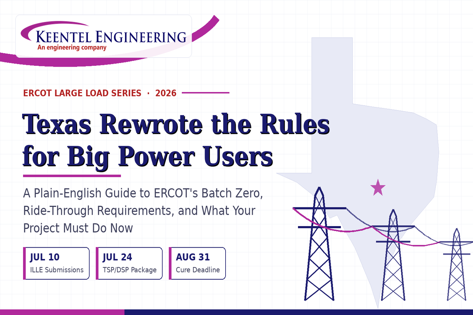
ERCOT enforces all of the above through simulation, which means your model is your compliance case. The bar is now high:
- Whole-facility scope. The model must represent everything the IT load, the UPS and power conversion, the cooling plant, the protection and control systems in formats compatible with ERCOT's study platforms (PSS/E, PSCAD, TSAT).
- Real control loops, not approximations. Generic textbook representations are unacceptable. The model must capture the actual inner control behavior of your power electronics.
- Hardware-validated converter models. For electronic loads, the PSCAD model must be benchmarked against actual hardware testing including voltage ride-through and subsynchronous response. A model assembled from standard PSCAD library blocks fails by definition, because a generic block has never been tested against your vendor's hardware. The good news: validation is a hardware-type test, so results for a given converter product are reusable across every facility that uses it.
- Format migration. Facilities that previously submitted the older composite load model (CMLD) format must transition to EPRI's PERC1 format.
- Three checkpoints. Models are reviewed before the stability study begins (no model, no study), before each quarterly stability assessment, and for electronic loads one final time before energization, when you must submit as-built models with a documented comparison against the previously studied data and a sworn attestation that the model matches actual field settings. ERCOT's review takes 10 business days, extendable by 20 put it on your critical path.
- A living obligation. Change your technology, controls, or relay settings in a way that affects ride-through including converting a crypto mining site to an AI data center — and you've triggered a new interconnection study, even if your megawatts don't change.
| Parameter | Detail |
|---|---|
| System | 230 kV / 138 kV transmission corridors, wind and wet-snow icing exposure |
| Data basis | 15 years of minute-resolution forced-outage records + regional weather observations |
| Core methods | Event grouping, MVA performance curves, time-to-95%-restore, area outage rate curves, fragility modeling, rerun-history benefits, exceedance and log-domain risk metrics |
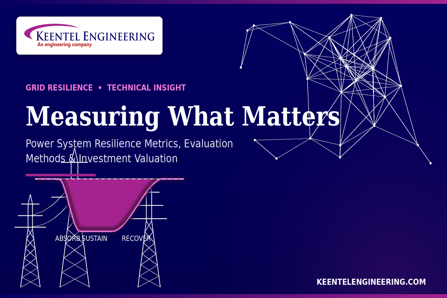
| Headline result | ≈85% of maximum resilience benefit at 60% of original capital; worst-event restoration window cut from 11 days to 5 in rerun-history terms |
| Decision supported | Capital portfolio selection; resilience plan filing; post-investment verification framework |
COMBINED CYCLE POWER PLANT (CCPP)
ELECTRICAL DESIGN ENGINEERING

Jul 07, 2026 | Blog
30% — 60% — 90% — IFC Milestone Scope, Deliverables & Studies
An IEEE/ANSI-Based Design Framework for Gas Turbine + Steam Turbine Generation
Notice & Disclaimer
This document is published by Keentel Engineering as original technical content for general informational purposes. It reflects Keentel Engineering's independent design methodology, professional experience, and interpretation of publicly available industry codes and standards.
IEEE, ANSI, NFPA, NEMA, UL, ICEA, NERC, and FERC, and all referenced standard designations, are trademarks or registered marks of their respective organizations. Keentel Engineering is not affiliated with, sponsored by, or endorsed by any of these organizations. References to codes and standards are provided for identification of governing design criteria only; the reader is responsible for obtaining and applying the current published editions.
Case studies contained herein are anonymized and generalized composites drawn from professional experience. Client names, project names, locations, and identifying commercial details have been removed or altered. Nothing in this document constitutes engineering services, a professional recommendation, or a substitute for project-specific engineering performed under the responsible charge of a licensed Professional Engineer.
© 2026 Keentel Engineering. All rights reserved.
1. Introduction: Why CCPP Electrical Design Lives or Dies at the Interconnection
A combined cycle power plant pairs a gas turbine with a steam turbine and recovers what a simple-cycle unit throws away. The gas turbine burns natural gas with compressed air; its hot exhaust — instead of venting to atmosphere — passes through a heat recovery steam generator (HRSG) that raises high-pressure steam to drive a second turbine and a second generator. The result is thermal efficiency in the 55–65% range against roughly 35–40% for a simple-cycle machine, with lower fuel burn per megawatt-hour, lower emissions intensity, fast start capability, and strong operating flexibility.
From an electrical engineering standpoint, a CCPP is really three interlocking systems: a generation and interconnection system at high voltage (two or more generators, generator step-up transformers, and a switchyard tied to the transmission grid); a plant auxiliary power system at medium and low voltage (13.8 kV switchgear feeding large motors, stepping down to 480 V for motor control centers and balance-of-plant loads); and an emergency and control power system (125 VDC batteries and UPS) that must ride through a total blackout to protect rotating equipment.
The Keentel Position
Grid interconnection is a first-order design input — not a downstream utility formality. On a CCPP, the point-of-interconnection requirements (short circuit duty, reactive capability, ride-through, protection interfaces, NERC modeling obligations) cascade backward into GSU impedance selection, generator capability curves, switchyard breaker ratings, and even the auxiliary system's ability to survive grid disturbances. Plants that treat interconnection as a late-stage checkbox routinely discover at 90% design that equipment already procured cannot satisfy POI requirements. We anchor the interconnection basis at 30%.
This document lays out the complete electrical engineering scope for a CCPP across the industry-standard design milestone progression — 30%, 60%, 90%, and Issued for Construction (IFC) — under the U.S. IEEE/ANSI framework, with a site basis of 13.8 kV medium voltage and 480 V low voltage. It closes with an engineering FAQ and three anonymized case studies from real project experience.
2. The CCPP Electrical Topology at a Glance
Before mapping scope to milestones, it helps to fix the reference single-line architecture that the design phases progressively mature:
- Gas turbine generator and steam turbine generator — typically 11–24 kV machine voltage (18 kV class is common for large frames), hydrogen- or air-cooled, each with its own excitation system and generator protection package.
- Generator step-up (GSU) transformers — designed per IEEE C57.12.00, connecting each generator (via isolated-phase bus on large frames) to the switchyard at transmission voltage.
- Switchyard / point of interconnection (POI) — high-voltage breakers rated per IEEE C37.06, disconnect switches, buswork, revenue metering, and the utility protection interface, laid out per NESC clearances.
- Unit auxiliary transformers (UAT) and station service transformers (SST) — tapping the generator bus or switchyard to feed the 13.8 kV medium-voltage auxiliary system.
- 13.8 kV MV switchgear — metal-clad, arc-resistant switchgear feeding boiler feed water pumps, circulating water pumps, condensate pumps, cooling tower fans on larger frames, and GT/ST auxiliary skids.
- 480 V LV switchgear and MCCs — fed from 13.8 kV–480 V station service transformers, powering motors under roughly 200 HP, valve actuators, package skids (water treatment, lube oil, fuel gas conditioning), HVAC, and lighting/small power via 480–208/120 V transformers.
- 125 VDC and UPS systems — station batteries sized per IEEE 485 to carry protection, switchgear control, turbine controls, and emergency lube oil pumps through a station blackout.
Five energy flows tie the plant together: natural gas fuel to the gas turbine; hot exhaust to the HRSG; the steam/condensate/feedwater loop through the steam turbine, condenser, condensate pumps, and boiler feed pumps; cooling water between the condenser and cooling tower; and electrical output from both generators to the grid. Every one of those mechanical flows has an electrical consequence — most visibly in the large motor loads that dominate the auxiliary load list.
3. Governing Codes & Standards Matrix (U.S. / IEEE-ANSI Basis)
The table below is the standards backbone Keentel applies to a U.S. CCPP electrical design. It is organized by system rather than by document number, because that is how the standards are actually invoked during design.
| System / Topic | Governing Standard(s) | What It Controls |
|---|---|---|
| Overall plant electrical distribution | IEEE 141 (Red Book); IEEE 666 | Distribution architecture, voltage selection, design of generating station auxiliary service systems |
| Power system studies | IEEE 399 (Brown Book); IEEE 551 | Load flow, symmetrical/asymmetrical short circuit, motor starting methodologies down to the lowest LV panelboard |
| Protection & coordination | IEEE 242 (Buff Book); IEEE 3004.5; IEEE C37 series | Generator relaying (21, 59N, 87G), time-current coordination, selective clearing between LV and MV tiers |
| GSU / UAT / SST transformers | IEEE C57.12.00 and C57 family | Transformer ratings, impedance, testing, loading |
| HV switchyard breakers | IEEE C37.06 | AC high-voltage circuit breaker preferred ratings |
| MV switchgear (13.8 kV) | IEEE C37.20.2; IEEE C37.20.7 | Metal-clad construction, compartmentalization, vacuum breakers; arc-resistant design with plenum venting |
| MV cable | UL 1072; ICEA S-93-639 (NEMA WC 74) | Type MV-105 shielded cable, 133% insulation level for HRG systems |
| LV switchgear (480 V) | IEEE C37.13; UL 1558 | Metal-enclosed LV power circuit breaker switchgear to 635 V, draw-out ACBs with electronic trip units |
| Motor control centers | UL 845; NEMA ICS 18 | LV-MCC construction, MCCB/MCP protection for motors under ~200 HP |
| Motors | NEMA MG-1 | Motor performance, starting characteristics, service factors |
| DC & battery systems | IEEE 485; IEEE 946 | Lead-acid battery sizing (125/250 VDC), DC auxiliary system design |
| Grounding | IEEE 80; IEEE 142 (Green Book) | Ground grid step/touch potential limits; system grounding including high-resistance grounding |
| Lightning protection | IEEE 998 | Direct-stroke shielding of switchyard and outdoor generator structures |
| Arc flash & electrical safety | IEEE 1584; NFPA 70E | Incident energy calculation; worker safety boundaries and PPE |
| Fire protection | NFPA 850 | Fire protection and risk management for combustion turbine generating plants |
| Installation code | NEC (NFPA 70); NESC | Wiring methods inside the plant fence; overhead/outdoor clearances at the switchyard |
| Interconnection & compliance | FERC LGIP; NERC MOD-025/026/027, PRC-019/024/029, FAC-008 | Interconnection process, model validation, protection/ride-through coordination, facility ratings |
Gas turbine generator packages are frequently manufactured overseas and arrive with IEC-designed components (IEC 60034 rotating machines, IEC 62271 switchgear). On a U.S. project these must be harmonized with the ANSI/IEEE basis of design — ratings translation, protection interface, and testing acceptance are recurring scope items that belong in the 30% design basis document, not in a construction-phase RFI.
4. The 30% Design Milestone Fixing the Basis Before It Fixes You
The 30% (preliminary/schematic) phase exists to make the decisions that are expensive to reverse. For a CCPP electrical scope, the deliverable set centers on the design basis, the overall one-line, the load list, and — critically — the interconnection inputs. Voltage class selection happens here: this reference design fixes 13.8 kV as the MV auxiliary bus and 480 V as the LV utilization voltage, with 4.16 kV noted as the common alternative for mid-size motor blocks where motor economics favor it. That decision drives switchgear ratings, cable systems, and transformer counts for the rest of the project.
30% Scope of Work
- Electrical design basis document: voltage classes (13.8 kV / 480 V / 125 VDC), grounding philosophy (HRG on MV auxiliaries per IEEE 142), short circuit design levels, codes and standards matrix, environmental and seismic criteria.
- Overall key one-line diagram: both generators, GSUs, switchyard arrangement, UAT/SST scheme, MV and LV bus structure, sources of station service and backup power.
- Preliminary auxiliary load list built from the mechanical equipment list — boiler feed water pumps, condensate pumps, circulating water pumps, cooling tower fans, GT/ST auxiliaries, HRSG loads — with duty cycles and diversity assumptions.
- Preliminary UAT/SST and GSU MVA sizing; generator terminal voltage and iso-phase bus concept for large frames.
- Switchyard concept plan: bus arrangement (ring, breaker-and-a-half, or single bus per POI requirements), preliminary equipment ratings per IEEE C37.06, NESC clearance envelope.
- Interconnection engineering inputs: FERC LGIP study data, preliminary power flow and short circuit models, reactive capability at the POI, preliminary NERC applicability review (MOD, PRC, FAC families).
- Preliminary equipment layout and electrical room sizing; hazardous area classification concept around fuel gas systems.
- Class 4/5 electrical quantities and cost input to the project estimate.
| 30% Deliverable | Maturity at This Milestone |
|---|---|
| Design basis document | Issued for review — voltage classes and grounding philosophy locked |
| Key one-line diagram | All major buses, sources, and transformations shown; ratings preliminary |
| Auxiliary load list | All major loads captured from mechanical list; ±25% margin carried |
| Interconnection study inputs | Submitted — POI requirements flowing back into design |
| Switchyard concept | Bus arrangement selected; footprint reserved |
| Equipment layout | Electrical rooms and cable routing corridors blocked out |
Why 30% Is the Interconnection Milestone
Every input the interconnection studies need — generator reactive capability, GSU impedance, switchyard topology, auxiliary load at the POI — is set at 30%. If those numbers change at 60% or 90%, the interconnection studies get re-run, the queue position may be at risk, and the schedule absorbs the hit. Keentel's practice is to treat the LGIP data submission as a controlled 30% deliverable with the same rigor as the one-line itself.
Step 5: Design Enhancement — Where the Money Is
At 60% (detailed design development), the architecture stops being conceptual. Equipment is sized and specified for procurement, the study suite produces its first real results, and the MV/LV systems take their final shape. This is the phase where long-lead procurement packages — GSUs, MV switchgear, generators' auxiliary interfaces — must be technically complete, because transformer and switchgear lead times drive the overall project schedule.
60% Scope of Work
- Finalized one-line diagrams for HV, MV, and LV systems, including bus ratings, breaker frame sizes, and transformer impedances.
- MV system detail design: 13.8 kV metal-clad, arc-resistant switchgear specification per IEEE C37.20.2 and C37.20.7 (compartmentalized construction, vacuum breakers, insulated bus, plenum exhaust routing); MV-105 shielded cable system per UL 1072/ICEA S-93-639 at the 133% insulation level required for the HRG grounding scheme.
- LV system detail design: 480 V metal-enclosed switchgear per IEEE C37.13/UL 1558 with draw-out air circuit breakers and electronic trip units; MCC lineups per UL 845/NEMA ICS 18 with MCCB/MCP protection; feeder and branch design to IEEE 141 voltage drop limits (3% branch, 5% total).
- Preliminary study suite per IEEE 399: load flow across operating scenarios (startup, base load, one-unit trip), first-pass short circuit per IEEE 551 to verify equipment interrupting duties, and motor starting studies confirming ≥85% terminal voltage on the largest MV motors (boiler feed pumps are usually the binding case).
- Procurement specifications: GSU and UAT/SST per IEEE C57.12.00, MV/LV switchgear, MCCs, DC systems, UPS, iso-phase bus, NEMA MG-1 large motors coordination with mechanical.
- Grounding grid preliminary design per IEEE 80 using measured soil resistivity; lightning shielding layout per IEEE 998 for the switchyard and outdoor structures.
- DC system sizing per IEEE 485: battery duty cycle built from the actual blackout load profile — protection, breaker control, turbine controls, emergency lube oil pumps — with IEEE 946 architecture (chargers, distribution, monitoring).
- Cable and raceway design development: tray routing, duct banks, segregation of power/control/instrumentation, preliminary cable schedule.
- Protection philosophy document: generator protection per IEEE 242 (21 distance backup, 59N stator ground, 87G differential, plus 40, 46, 24, 81 elements), transformer differential zones, MV/LV coordination strategy.
| 60% Deliverable | Maturity at This Milestone |
|---|---|
| HV/MV/LV one-lines | Issued for design — ratings and impedances final |
| MV & LV switchgear specifications | Issued for procurement (long-lead release) |
| GSU / UAT / SST specifications | Issued for procurement (long-lead release) |
| Load flow / short circuit / motor starting | First full pass complete; equipment duties verified |
| Grounding & lightning design | Grid model built on soil data; shielding layout drafted |
| DC & UPS sizing | Battery duty cycle calculated per IEEE 485 |
| Cable & raceway design | Routing established; schedule ~50% populated |
| Protection philosophy | Issued — relay functions and zones defined |
6. The 90% Design Milestone — Studies Closed, Settings Issued, Field-Ready
At 90%, the design must be construction-complete in substance; only vendor-data backfill and final review comments separate it from IFC. The study suite is finalized against actual purchased-equipment data (real transformer test impedances, real motor characteristics, real relay models), protection settings are calculated, and the arc flash analysis produces the labels that will physically go on the gear.
90% Scope of Work
- Final power system studies per IEEE 399/551 using as-purchased equipment data: load flow, short circuit to the lowest 480 V panelboard with AIC margins verified, motor starting re-run with certified motor curves.
- Protection coordination study per IEEE 242/3004.5: complete time-current characteristic (TCC) sets demonstrating that a 480 V fault clears at its MCC breaker before the upstream 13.8 kV feeder responds, generator and transformer relay settings per the protection philosophy, coordination with the utility's POI relaying.
- Arc flash hazard analysis per IEEE 1584 and NFPA 70E: incident energy at every bus, label schedule, and mitigation design where categories are unacceptable (maintenance-mode switching, arc-resistant credit, remote racking).
- NERC compliance engineering: PRC-019 coordination of generator voltage regulation controls and protection, PRC-024 (transitioning to PRC-029 for applicable resources) frequency/voltage ride-through verification, MOD-025/026/027 test plans, FAC-008 facility ratings methodology.
- Final grounding grid design per IEEE 80 with step/touch potentials demonstrated below tolerable limits; final IEEE 998 shielding verification.
- Complete cable schedule, conduit/tray fill calculations, cable pulling calculations, and raceway drawings; segregation and separation verified.
- Full drawing set at 90%: one-lines, three-lines, schematics, wiring diagrams, panel schedules, grounding plans, lighting, cathodic protection interfaces, hazardous area drawings.
- Relay settings files drafted for the microprocessor protection platform; SCADA/DCS I/O lists and network architecture coordinated with controls.
| 90% Deliverable | Maturity at This Milestone |
|---|---|
| Final study suite (LF/SC/MS) | Closed on as-purchased data; report issued |
| Protection coordination & TCCs | Complete; utility interface coordinated |
| Arc flash analysis & labels | Complete per IEEE 1584; mitigation designed |
| NERC compliance package | PRC-019/024(029), MOD test plans, FAC-008 drafted |
| Grounding & lightning | Final — step/touch compliance demonstrated |
| Cable schedule & raceway | 100% populated; fills and pulls calculated |
| Drawing set | All disciplines at 90%; vendor data incorporated |
| Relay settings | Draft settings files issued for review |
The 90% Trap
The most common CCPP failure mode at 90% is a study suite still running on assumed data. If the coordination study and arc flash analysis are built on estimated transformer impedances instead of factory test reports, the settings and labels issued at IFC are fiction — and the plant inherits the liability. Keentel gates the 90% studies on receipt of certified vendor data, and flags the gap on the milestone certificate if vendors are late.
7. IFC — Issued for Construction and Beyond
IFC is not a drafting exercise; it is the point at which the engineer of record stakes a license on the package. Every review comment is closed, every hold is lifted, every calculation is checked and signed, and the drawings are stamped by the responsible Professional Engineer.
IFC Scope of Work
- Stamped, signed IFC drawing and specification packages for all electrical systems, incorporating final vendor data and constructability review comments.
- Final relay settings issued under configuration control, with setting sheets traceable to the coordination study revision.
- Final calculations package: studies, grounding, DC sizing, voltage drop, cable ampacity and derating, lighting — indexed and archived for the owner and for NERC evidence.
- Commissioning support documents: energization sequence, protection functional test plans, MOD-025/026/027 field test procedures, breaker and transformer acceptance test criteria.
- Construction-phase engineering: RFI responses, field change management, factory and site acceptance test witness, red-line capture.
- As-built close-out: conformed drawings, final settings as-left records, updated models delivered to the owner for ongoing NERC MOD compliance.
| IFC / Construction Deliverable | Purpose |
|---|---|
| Stamped IFC packages | Legal basis for construction; P.E. responsible charge |
| Final relay settings & TCCs | Protection as-installed matches the coordination study |
| Calculation archive | Owner records; NERC audit evidence trail |
| Commissioning procedures | Safe, sequenced energization; MOD field testing |
| Construction support | RFIs, field changes, FAT/SAT witness |
| As-builts & model handoff | Operating baseline; future study currency |
8. The Study Suite: The Analytical Spine of All Four Milestones
Studies are not a milestone deliverable so much as a thread that runs through all four. Each study matures in lockstep with data quality:
| Study | Standard | 30% | 60% | 90% / IFC |
|---|---|---|---|---|
| Load flow | IEEE 399 | Concept scenarios | All operating cases | Final on vendor data |
| Short circuit | IEEE 399 / 551 | Design levels set | Duties verified | AIC margins closed to lowest panel |
| Motor starting | IEEE 399 | Screening (largest motors) | ≥85% terminal V confirmed | Certified curves; VFD/soft-start where needed |
| Coordination | IEEE 242 / 3004.5 | Philosophy | Preliminary TCCs | Final TCCs + settings |
| Arc flash | IEEE 1584 / NFPA 70E | — | Preliminary energies | Final labels + mitigation |
| Grounding | IEEE 80 | Soil resistivity program | Grid model | Step/touch compliance |
| Interconnection | FERC LGIP / NERC MOD-PRC | Study data submitted | Results absorbed into design | Compliance evidence & field tests |
How Keentel Delivers This Scope
Keentel Engineering provides CCPP electrical design as a full owner's engineer or detailed-design scope — one-lines through IFC, the complete IEEE 399 study suite, protection and settings, grounding, DC systems, and the interconnection and NERC compliance layer that most design firms treat as someone else's problem. Because our practice is built around grid interconnection, the POI requirements are engineered into the plant from the 30% design basis, not discovered at commissioning.
Case Study
Case Study 1 — 2×1 CCPP: Interconnection Requirements Rescued at 30%
Profile: A nominal 700 MW-class 2×1 combined cycle facility (two gas turbines, two HRSGs, one steam turbine) interconnecting to a 230 kV transmission system in a U.S. RTO footprint. Keentel's role: electrical design lead and interconnection engineer. All identifying details anonymized.
The Challenge
The developer had inherited a conceptual design from an earlier feasibility effort in which the GSU impedances and switchyard arrangement had been chosen for cost, with the interconnection application treated as a parallel administrative track. Early cluster study results indicated the POI short circuit duty was near the interrupting capability of the assumed 230 kV breakers, and the reactive range the interconnection agreement would require at the POI could not be delivered through the assumed GSU impedance across the full generator capability curve.
The Keentel Approach
- Rebuilt the 30% design basis with the interconnection requirements as first-order inputs: POI reactive envelope, ride-through obligations, and short circuit headroom were written into the basis document alongside voltage classes and grounding philosophy.
- Re-optimized GSU impedance jointly against short circuit contribution and reactive transfer, iterating the interconnection power flow cases with the plant one-line rather than treating them as separate models.
- Moved the switchyard from a single-bus concept to a breaker-and-a-half arrangement with breaker ratings selected per IEEE C37.06 against the study-derived duty plus system growth margin.
- Locked the LGIP data submission as a controlled 30% deliverable with a formal design freeze on interconnection-coupled parameters.
The Outcome
The revised parameters passed the restudy without a queue position change, and no interconnection-driven equipment change occurred after 30%. The GSUs were released for procurement at 60% against final, study-consistent impedances. The developer's independent engineer specifically credited the integrated interconnection/plant-design model with removing what it had flagged as the project's largest single schedule risk.
Case Study 2 — MV/LV Auxiliary System: HRG and Arc Flash Engineered Together
Profile: A 500 MW-class 1×1 combined cycle plant with a 13.8 kV auxiliary backbone and 480 V utilization system. Keentel's role: MV/LV detail design, protection, and safety studies from 60% through IFC. All identifying details anonymized.
The Challenge
The plant's availability model could not tolerate an auxiliary bus trip on a single line-to-ground fault — a forced GT runback traced to a grounded cable had burned the owner on a prior asset. Simultaneously, preliminary arc flash screening showed several 480 V switchgear buses trending toward incident energies that would have made routine racking operations impractical under NFPA 70E.
The Keentel Approach
- Implemented high-resistance grounding on the 13.8 kV auxiliary system per IEEE 142, with pulsing ground-fault location and alarm-and-locate operating procedures, so a first ground fault alarms rather than trips.
- Carried the HRG decision through its consequences: MV-105 shielded cable at 133% insulation level per UL 1072/ICEA S-93-639, and charging-current verification to keep the fault current within the resistor's design window.
- Specified arc-resistant 13.8 kV metal-clad switchgear per IEEE C37.20.7 with engineered plenum exhaust routing coordinated with the building design — a detail frequently discovered as an interference at construction.
- On the 480 V system, combined IEEE C37.13/UL 1558 switchgear with electronic trip units and a maintenance-mode (arc energy reduction) switching scheme, then re-ran IEEE 1584 with maintenance mode credited to bring worst-case buses into workable categories.
- Delivered the full TCC coordination set per IEEE 242/3004.5 demonstrating an LV fault clears at its MCC breaker before the 13.8 kV feeder relay responds — selective clearing preserved despite the fast maintenance-mode settings.
The Outcome
The plant entered commercial operation with a single-ground-fault ride-through capability on its MV auxiliaries, arc flash labels at every bus reflecting the mitigated energies, and a coordination study that survived the utility's POI relaying review without a settings change. In its first operating year, one MV cable ground fault was located and repaired during a planned reduction rather than forcing a unit trip — the exact scenario the design was built for.
Case Study 3 — Fast-Track Brownfield Addition: Motor Starting and the Study Suite Under Schedule Pressure
Profile: A gas turbine and HRSG addition converting an existing simple-cycle site to combined cycle, with new boiler feed water pumps and cooling infrastructure added to an aging auxiliary system. Keentel's role: power system studies, auxiliary system upgrade design, and IFC protection settings on a compressed schedule. All identifying details anonymized.
The Challenge
The conversion added multi-thousand-horsepower boiler feed pump motors to a station service system originally sized for simple-cycle auxiliaries. Screening showed motor terminal voltage during BFP acceleration falling well below the 85% threshold under the weakest credible source configuration, and the legacy switchgear's interrupting ratings had never been re-verified against decades of transmission system growth. IFC was contractually fixed; the studies could not slip.
The Keentel Approach
- Executed the IEEE 399 suite as a single integrated model — load flow, IEEE 551 short circuit to the lowest 480 V panelboard, and dynamic motor starting — so every design change propagated through all three analyses in one pass instead of three sequential revisions.
- Resolved the BFP starting problem with variable frequency drives, which eliminated the voltage-dip constraint, cut pump energy at part load, and removed a planned UAT upsizing from the project scope.
- Identified two legacy MV breakers with insufficient interrupting margin against present-day duty; specified replacements within the existing lineup footprint to avoid switchgear building modifications.
- Gated the 90% studies on certified factory test data for the new transformers and motors, and issued the IEEE 1584 arc flash labels and final relay settings from that verified model under configuration control.
The Outcome
The addition energized on the contractual date. First BFP starts matched the dynamic study predictions within measurement tolerance, the replaced breakers cleared their commissioning duties with verified margin, and the owner received a single indexed calculation archive that has since served as the plant's NERC evidence baseline. The VFD decision, made analytically at 60% rather than as a field fix, was later estimated by the owner to have paid for the entire study scope several times over.
13. About Keentel Engineering
Keentel Engineering is a power systems consulting firm specializing in grid interconnection, generation and substation design, transmission engineering, and NERC compliance. Our practice spans EMT and PSS/E modeling, POI interconnection engineering, utility-scale generation and storage design, owner's engineer services, and the milestone-based detailed design delivery described in this document.
What differentiates our CCPP work is the integration of interconnection engineering with plant electrical design under one roof — the same team that builds your one-lines builds your LGIP models, coordinates your POI protection, and assembles your NERC evidence. Interconnection is a first-order design input in our process, and it shows in schedules that hold.
Engage Keentel
For CCPP electrical design, owner's engineer support, interconnection studies, or NERC compliance engineering, contact Keentel Engineering — Tampa, FL • Austin, TX. Deliverables are executed under the responsible charge of a licensed Professional Engineer.
Frequently Asked Questions
Q1. Why are CCPP designs delivered in 30% / 60% / 90% / IFC stages instead of one continuous effort?
Milestones create controlled decision gates. The 30% package locks the decisions that are costly to reverse (voltage classes, grounding philosophy, switchyard topology, interconnection data); 60% releases long-lead procurement; 90% closes the studies on real equipment data; IFC transfers a stamped, license-backed package to the field. Each gate is also a natural point for owner review, estimate refinement, and constructability input.
Q2. Why 13.8 kV for the MV auxiliary bus rather than 4.16 kV?
13.8 kV reduces feeder currents and cable quantities for a large auxiliary load block and matches common UAT/SST secondary ratings. 4.16 kV remains attractive where the motor population clusters in the 250–3,000 HP range, since 4 kV motors and starters can be more economical. Many large CCPPs use both. The selection is a 30% design basis decision driven by the load list, not a default.
Q3. What does high-resistance grounding (HRG) buy on the MV auxiliary system?
Per IEEE 142, HRG limits ground fault current to a few amps, letting the plant ride through a single line-to-ground fault without an immediate trip — a major availability benefit on continuous-process auxiliaries. The costs are disciplined follow-through: 133% insulation level MV cable per ICEA S-93-639, ground fault alarm and location capability, and an operating procedure to find and clear the fault before a second one escalates it.
Q4. Which generator protection functions govern the design?
The IEEE 242 baseline package for a CCPP generator includes 87G differential, 59N stator ground (often with 100% coverage via third-harmonic or injection schemes), 21 distance backup, 40 loss-of-field, 46 negative sequence, 24 V/Hz, 81 over/under frequency, and 32 reverse power — coordinated with the GSU differential zone and, critically, with the excitation limiters per NERC PRC-019.
Q5. What drives GSU and UAT sizing?
The GSU is sized to the generator's full MVA capability at its rated power factor with impedance selected as a balance between short circuit contribution at the POI and voltage regulation/reactive transfer capability — an interconnection-study-coupled decision. The UAT is sized to the worst-case simultaneous auxiliary demand (usually startup or one-unit-trip scenarios from the load flow), with margin for future loads.
Q6. Where do motor starting problems usually show up in a CCPP?
The boiler feed water pumps are almost always the binding case — large MV motors starting against a system whose strength depends on operating configuration. IEEE guidance and good practice require ≥85% terminal voltage during acceleration; when a weak startup source can't deliver it, the fixes are a stiffer UAT tap, reduced-voltage starting, VFDs (which many modern plants adopt for BFP efficiency anyway), or staged starting sequences.
Q7. What is the difference between arc-resistant switchgear and an arc flash study?
They are complementary. Arc-resistant MV switchgear per IEEE C37.20.7 is a containment design — it redirects arc plasma through plenums away from personnel. The IEEE 1584 arc flash study is an analysis that quantifies incident energy at every bus and sets the NFPA 70E boundaries and PPE. Arc-resistant construction can reduce the practical exposure but does not eliminate the need for the study, labels, or safe work practices.
Q8. How do NERC requirements enter a plant design that hasn't even been built yet?
Several standards are design-determinative. PRC-019 requires coordination between excitation limiters and protection settings — a 90% deliverable. PRC-024 (and PRC-029 for applicable inverter-interfaced and newer resources) sets ride-through envelopes that the protection settings must respect. MOD-025/026/027 require validated models, which means the design models must be built to be field-verifiable. FAC-008 requires a facility ratings methodology consistent with the design calculations. Retrofitting compliance after COD is far more expensive than designing it in.
Q9. What belongs in the 125 VDC battery duty cycle?
Per IEEE 485, the duty cycle is built from the actual blackout sequence: continuous loads (protection, controls, indication), momentary loads (breaker tripping and closing), and the long-duration loads that protect rotating equipment — above all the emergency lube oil pumps for the turbine-generators. Battery sizing failures are almost always duty-cycle omissions, not calculation errors.
Q10. Can IEC-built equipment be used on an IEEE-basis U.S. plant?
Yes, and on OEM turbine packages it is often unavoidable — but it must be engineered, not assumed. Ratings translation (IEC 60034 machines, IEC 62271 switchgear), protection CT/VT compatibility, insulation coordination, and acceptance testing against the ANSI basis are explicit scope items. The design basis document should state the harmonization approach at 30%.
Q11. What voltage drop limits apply on the 480 V system?
IEEE 141 practice: 3% maximum steady-state drop on branch circuits and 5% total across feeder plus branch at full load. On a CCPP, the long runs to cooling tower MCCs and remote skids are the usual offenders, and the fix is cheaper at 60% (conductor sizing, MCC placement) than at commissioning.
Q12. Who should perform the interconnection engineering — the plant designer or a separate consultant?
The work products are inseparable from the plant design: the LGIP models are built from the same one-line, the POI short circuit duty constrains the same switchyard breakers, and the NERC evidence comes from the same calculations. Splitting them creates interface risk. Keentel's model is to carry interconnection and plant electrical design as one integrated scope, which is precisely why interconnection issues surface at 30% instead of at energization.

About the Author:
Sonny Patel P.E. EC
IEEE Senior Member
In 1995, Sandip (Sonny) R. Patel earned his Electrical Engineering degree from the University of Illinois, specializing in Electrical Engineering . But degrees don’t build legacies—action does. For three decades, he’s been shaping the future of engineering, not just as a licensed Professional Engineer across multiple states (Florida, California, New York, West Virginia, and Minnesota), but as a doer. A builder. A leader. Not just an engineer. A Licensed Electrical Contractor in Florida with an Unlimited EC license. Not just an executive. The founder and CEO of KEENTEL LLC—where expertise meets execution. Three decades. Multiple states. Endless impact.
Services

Let's Discuss Your Project
Let's book a call to discuss your electrical engineering project that we can help you with.
About the Author:
Sonny Patel P.E. EC
IEEE Senior Member
In 1995, Sandip (Sonny) R. Patel earned his Electrical Engineering degree from the University of Illinois, specializing in Electrical Engineering . But degrees don’t build legacies—action does. For three decades, he’s been shaping the future of engineering, not just as a licensed Professional Engineer across multiple states (Florida, California, New York, West Virginia, and Minnesota), but as a doer. A builder. A leader. Not just an engineer. A Licensed Electrical Contractor in Florida with an Unlimited EC license. Not just an executive. The founder and CEO of KEENTEL LLC—where expertise meets execution. Three decades. Multiple states. Endless impact.
Leave a Comment
We will get back to you as soon as possible.
Please try again later.
Related Posts