
A Coordinated Electric System Interconnection Review—the utility’s deep-dive on technical and cost impacts of your project.
Challenge: Frequent false tripping using conventional electromechanical relays
Solution: SEL-487E integration with multi-terminal differential protection and dynamic inrush restraint
Result: 90% reduction in false trips, saving over $250,000 in downtime
ERCOT enforces all of the above through simulation, which means your model is your compliance case. The bar is now high:
- Whole-facility scope. The model must represent everything the IT load, the UPS and power conversion, the cooling plant, the protection and control systems in formats compatible with ERCOT's study platforms (PSS/E, PSCAD, TSAT).
- Real control loops, not approximations. Generic textbook representations are unacceptable. The model must capture the actual inner control behavior of your power electronics.
- Hardware-validated converter models. For electronic loads, the PSCAD model must be benchmarked against actual hardware testing including voltage ride-through and subsynchronous response. A model assembled from standard PSCAD library blocks fails by definition, because a generic block has never been tested against your vendor's hardware. The good news: validation is a hardware-type test, so results for a given converter product are reusable across every facility that uses it.
- Format migration. Facilities that previously submitted the older composite load model (CMLD) format must transition to EPRI's PERC1 format.
- Three checkpoints. Models are reviewed before the stability study begins (no model, no study), before each quarterly stability assessment, and for electronic loads one final time before energization, when you must submit as-built models with a documented comparison against the previously studied data and a sworn attestation that the model matches actual field settings. ERCOT's review takes 10 business days, extendable by 20 put it on your critical path.
- A living obligation. Change your technology, controls, or relay settings in a way that affects ride-through including converting a crypto mining site to an AI data center — and you've triggered a new interconnection study, even if your megawatts don't change.
| Parameter | Detail |
|---|---|
| System | 230 kV / 138 kV transmission corridors, wind and wet-snow icing exposure |
| Data basis | 15 years of minute-resolution forced-outage records + regional weather observations |
| Core methods | Event grouping, MVA performance curves, time-to-95%-restore, area outage rate curves, fragility modeling, rerun-history benefits, exceedance and log-domain risk metrics |
| Headline result | ≈85% of maximum resilience benefit at 60% of original capital; worst-event restoration window cut from 11 days to 5 in rerun-history terms |
| Decision supported | Capital portfolio selection; resilience plan filing; post-investment verification framework |
| System / Topic | Governing Standard(s) | What It Controls |
|---|---|---|
| Overall plant electrical distribution | IEEE 141 (Red Book); IEEE 666 | Distribution architecture, voltage selection, design of generating station auxiliary service systems |
| Power system studies | IEEE 399 (Brown Book); IEEE 551 | Load flow, symmetrical/asymmetrical short circuit, motor starting methodologies down to the lowest LV panelboard |
| Protection & coordination | IEEE 242 (Buff Book); IEEE 3004.5; IEEE C37 series | Generator relaying (21, 59N, 87G), time-current coordination, selective clearing between LV and MV tiers |
| GSU / UAT / SST transformers | IEEE C57.12.00 and C57 family | Transformer ratings, impedance, testing, loading |
| HV switchyard breakers | IEEE C37.06 | AC high-voltage circuit breaker preferred ratings |
| MV switchgear (13.8 kV) | IEEE C37.20.2; IEEE C37.20.7 | Metal-clad construction, compartmentalization, vacuum breakers; arc-resistant design with plenum venting |
| MV cable | UL 1072; ICEA S-93-639 (NEMA WC 74) | Type MV-105 shielded cable, 133% insulation level for HRG systems |
| LV switchgear (480 V) | IEEE C37.13; UL 1558 | Metal-enclosed LV power circuit breaker switchgear to 635 V, draw-out ACBs with electronic trip units |
| Motor control centers | UL 845; NEMA ICS 18 | LV-MCC construction, MCCB/MCP protection for motors under ~200 HP |
| Motors | NEMA MG-1 | Motor performance, starting characteristics, service factors |
| DC & battery systems | IEEE 485; IEEE 946 | Lead-acid battery sizing (125/250 VDC), DC auxiliary system design |
| Grounding | IEEE 80; IEEE 142 (Green Book) | Ground grid step/touch potential limits; system grounding including high-resistance grounding |
| Lightning protection | IEEE 998 | Direct-stroke shielding of switchyard and outdoor generator structures |
| Arc flash & electrical safety | IEEE 1584; NFPA 70E | Incident energy calculation; worker safety boundaries and PPE |
| Fire protection | NFPA 850 | Fire protection and risk management for combustion turbine generating plants |
| Installation code | NEC (NFPA 70); NESC | Wiring methods inside the plant fence; overhead/outdoor clearances at the switchyard |
| Interconnection & compliance | FERC LGIP; NERC MOD-025/026/027, PRC-019/024/029, FAC-008 | Interconnection process, model validation, protection/ride-through coordination, facility ratings |
| IFC / Construction Deliverable | Purpose |
|---|---|
| Stamped IFC packages | Legal basis for construction; P.E. responsible charge |
| Final relay settings & TCCs | Protection as-installed matches the coordination study |
| Calculation archive | Owner records; NERC audit evidence trail |
| Commissioning procedures | Safe, sequenced energization; MOD field testing |
| Construction support | RFIs, field changes, FAT/SAT witness |
| As-builts & model handoff | Operating baseline; future study currency |
| Metric | Outcome |
|---|---|
| Defects found pre-occupancy | Three topology defects and one settings-mismatch family corrected before load migration; the shared-switchboard defect alone would have invalidated the concurrently-maintainable claim on day one |
| IST findings | Fourteen additional discrepancies surfaced under scenario testing (control logic, alarm mapping, one generator sequencing fault) — all closed before handover instead of during operations |
| Black-building test | Passed on second execution; the first attempt exposed the generator sequencing fault under true block load, exactly the failure the compressed plan would never have found |
| Handover quality | Operations team certified on the actual failure scenarios; corrected EOPs and settings documentation delivered as controlled documents |
| Business outcome | Occupancy proceeded three weeks behind the original date — against an independent estimate that the uncorrected sequencing fault carried a high probability of a full facility outage within the first year |
Part 2 — Frequently Asked Questions: Large Load Interconnection
An electric grid must remain in continuous balance — generation onto the grid must equal consumption from it at every instant. PJM achieves this balance, and prices it, through a layered market architecture. Each layer operates on a different time horizon, and each one touches project economics differently.
| Domain | Key Standards / Codes | What They Govern |
|---|---|---|
| Fire safety | NFPA 855; UL 9540 / UL 9540A | Installation requirements, separation, gas management; system safety listing and thermal-runaway fire testing |
| Grid interconnection | IEEE 1547 (distribution); IEEE 2800 (transmission IBRs) | Ride-through, reactive capability, power quality, and performance at the point of interconnection |
| Power quality | IEEE 519 | Harmonic distortion limits at the PCC |
| Protection & grounding | IEEE 80 / 81 / 142; C37 series | Grounding system design and testing; protective relaying |
| Reliability compliance | NERC standards (incl. PRC ride-through requirements) | Registered-entity obligations for grid-connected storage |
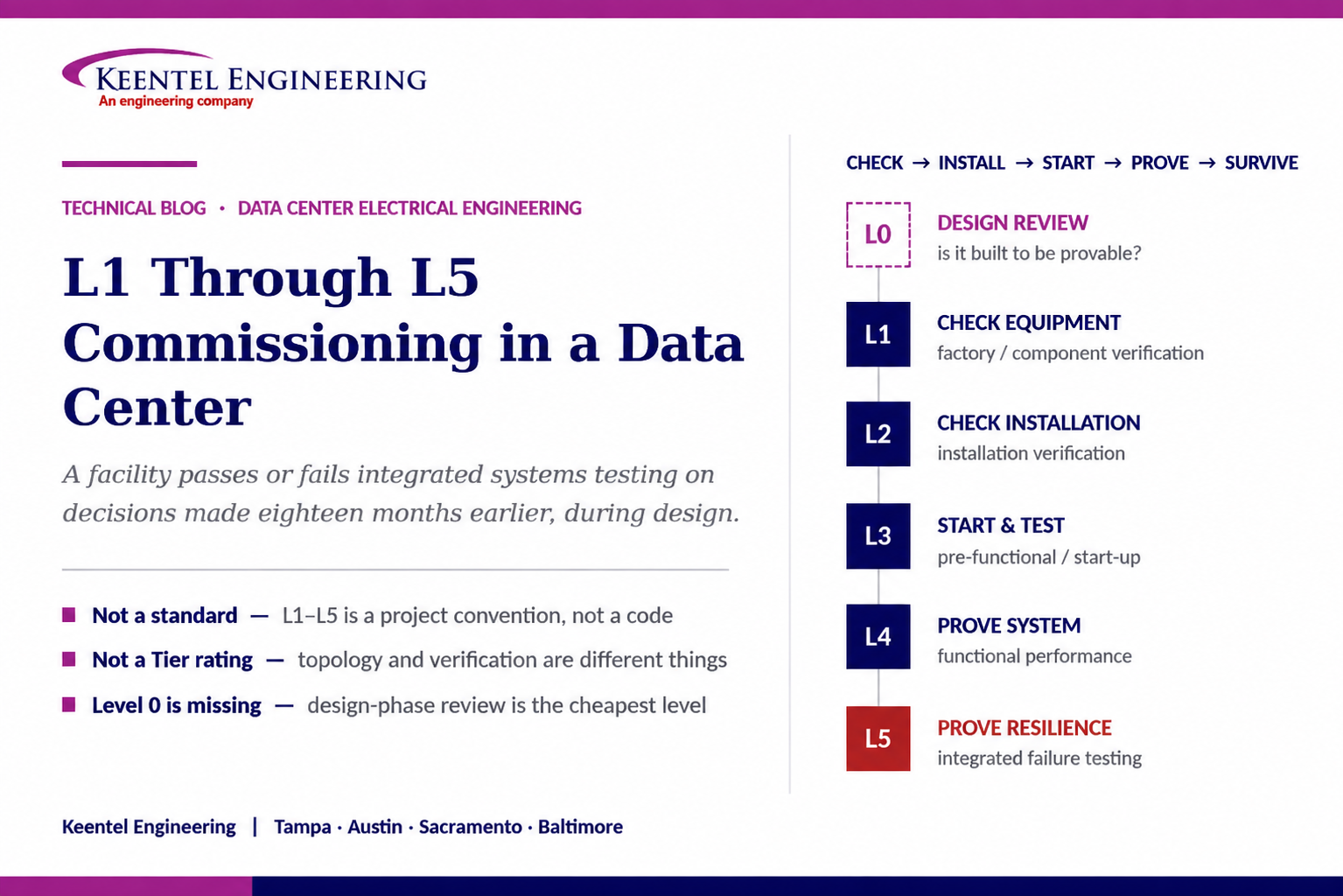
L1 Through L5 Commissioning in a Data Center
Aug 28, 2026 | Blog
What Each Level Actually Tests, Why the Facility Either Passes or Fails Integrated Systems Testing on Decisions Made During Design, and How to Engineer a Facility That Can Be Proven
1. Executive Summary
A data center is the only building type routinely required to prove, before a single production workload is placed on it, that it will survive the loss of its utility feed, the failure of a chiller, the failure of a UPS module, and a control system alarm storm — simultaneously, at full design load, in front of the owner. That proof is the commissioning programme, and in most projects it is organised into levels commonly labelled L1 through L5.
The levels are widely used and almost never defined the same way twice. They are not a code, not a standard, and not a certification. They are a project convention that has to be written into the commissioning plan and the contract documents, because the difference between one party's L4 and another's L5 is measured in weeks of schedule and hundreds of thousands of dollars of load bank rental.
The more consequential point is this: integrated systems testing does not fail because of how it is executed. It fails because of decisions made eighteen months earlier in design. A generator sized on steady-state kW without regard to step-load acceptance or the harmonic interaction with the UPS input will not carry the block load at L5. A single-line diagram without maintenance bypass around every critical device cannot demonstrate concurrent maintainability regardless of how the test is written. A facility with no permanent load bank connection will be tested once, expensively, and never again.
This paper works through each level in engineering detail — the specific tests, the standards behind them, and the acceptance criteria — and then works backwards to the design decisions that determine whether those tests can be passed. It closes with a defect taxonomy drawn from what commissioning programmes actually find, a section on designing for testability, and a twenty-question FAQ.
The framing that matters
Commissioning is not a construction-phase activity that verifies a finished design. It is a design-phase discipline that produces a facility capable of being verified.
Every test script at L5 should trace back to a line in the Owner's Project Requirements and a corresponding decision in the Basis of Design. If a requirement is not in the OPR, no one will test it. If a design decision is not in the BOD, no one will know what "pass" means.
2. Three Numbering Systems That Are Not the Same Thing
Three separate numbering conventions circulate in data center work, and conflating them is the most common source of confusion in owner conversations. They measure different things and are produced by different bodies.
| System | What it describes | Who defines it | What it does not tell you |
|---|---|---|---|
| L1 – L5 commissioning levels | The sequence of verification activities, from factory testing through integrated failure-scenario testing | Project convention; defined in the project commissioning plan. Related process guidance exists in ASHRAE Guideline 0 and ASHRAE Standard 202, and data-center-specific guidance in BICSI 002 | Nothing about the facility’s redundancy topology or availability class. A Tier II facility and a Tier IV facility both go through L1 to L5 |
| Uptime Institute Tier I – IV | The topology and capability of the facility: redundant components, multiple distribution paths, concurrent maintainability, fault tolerance | Uptime Institute, through Tier Certification of Design Documents, of Constructed Facility, and of Operational Sustainability | Nothing about whether the installed systems have been individually tested. Design certification reviews documents; constructed-facility certification includes demonstration |
| TIA-942 Rated-1 – Rated-4 | A rating across telecommunications, architectural, electrical, and mechanical criteria for data center infrastructure | TIA-942 standard, with conformity assessment through accredited certification bodies | It is a different scheme from Uptime tiers despite similar numbering, and the criteria and assessment process differ |
The practical consequence for an owner is that all three may appear in the same project. A facility can be designed to Uptime Tier III concurrent maintainability, carry a TIA-942 rating claim, and be commissioned through a five-level programme. None of the three substitutes for the others, and the commissioning programme is the only one of the three that produces evidence the installed equipment actually works.
3. Level 0 — The Level Most Programs Omit
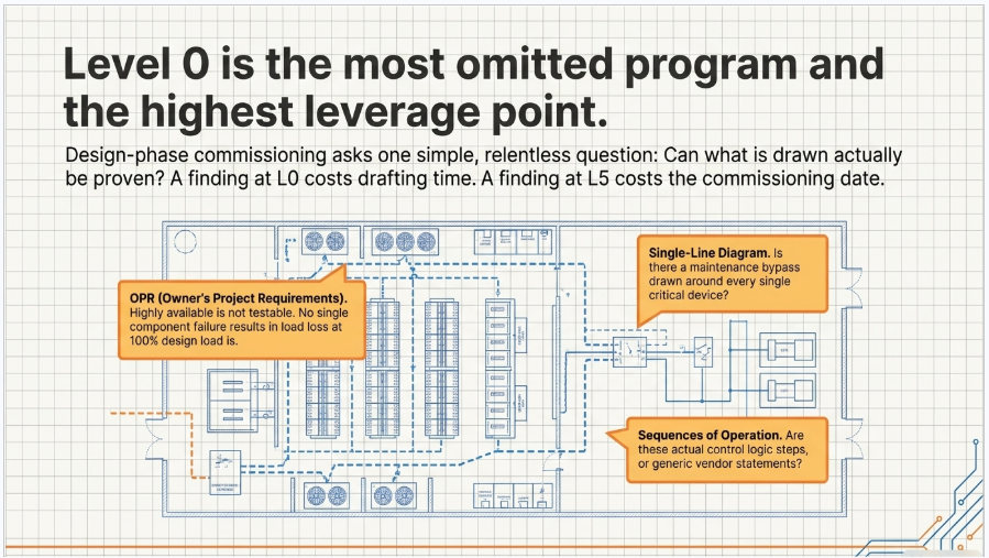
Most L1-to-L5 charts begin at the factory. The highest-leverage level begins earlier, during design, and is variously called Level 0, design-phase commissioning, or commissioning design review. Its omission is the single most common structural weakness in a commissioning programme.
Design-phase commissioning has a narrow and specific scope. It is not a peer review of the design and it is not value engineering. It asks one question repeatedly: can what is drawn be proven to satisfy what the owner asked for?
3.1 What Level 0 Actually Reviews
- Owner's Project Requirements — is every availability, capacity, density, and operational requirement written in terms that can be measured? "Highly available" is not testable. "No single component failure results in loss of IT load, demonstrated at 100 percent of design load" is.
- Basis of Design — does every OPR requirement have a corresponding engineering decision, with the assumptions stated? Generator step-load capability, UPS transfer criteria, thermal ride-through duration, allowable rack inlet temperature excursion.
- Single-line diagram against the maintainability requirement — is there a maintenance bypass around every device that must be serviced without dropping load? Can each distribution path be de-energised in turn with the load carried on the other?
- Sequences of operation — do they exist, in writing, in enough detail that a test script can be written from them? A sequence that says "generators start on loss of utility" is not a sequence. Start signal source, time delay, load block order, and failure-to-start logic are the sequence.
- Testability provisions — permanent load bank connections and their capacity, test-position breakers, metering and trending points, temporary power provisions for the test programme itself.
- Study executability — will the protective coordination study produce settings that can actually be entered into the specified devices, and are the devices field-adjustable to the settings the study requires?
A Level 0 finding is worth roughly a hundred times the same finding at L5
Changing a single-line diagram during design costs drafting time. Adding a maintenance bypass after the switchgear is manufactured costs a change order, a factory slot, and schedule. Discovering at integrated systems testing that concurrent maintainability cannot be demonstrated costs the commissioning date.
4. L1 — Factory and Component Verification
Level 1 answers whether the equipment was manufactured and supplied correctly. Its centre of gravity is factory acceptance testing, but the valuable work happens before the plane ticket is booked: reviewing the manufacturer's test procedure against the specification and the design intent, and deciding what will be witnessed versus what will be accepted on certified report.
4.1 Electrical Equipment
- Medium-voltage switchgear — design and production test evidence per the applicable switchgear standards, including power-frequency withstand, mechanical operation, control wiring verification, and, where specified, arc-resistant construction type test evidence for the accessibility class being purchased.
- Power and distribution transformers — routine tests per the applicable transformer test code: turns ratio, polarity and phase relation, winding resistance, no-load and load losses, impedance, insulation power factor, applied and induced potential. Impulse and temperature-rise tests where specified. Verify the tested unit is the unit being shipped by serial number.
- Uninterruptible power supplies — efficiency at multiple load points, input current distortion, transfer performance to and from bypass, overload capability, battery runtime at design load, and the behaviour of any high-efficiency or eco-mode operating state, which is where transfer performance most often disappoints.
- Generator sets — governor and voltage regulator response, block load acceptance in the steps the application requires, transient voltage and frequency dip and recovery against the declared performance class, and alternator temperature rise at rated power factor. Testing at unity power factor when the machine will run at 0.8 lagging is a common and consequential shortcut.
- Switchboards, PDUs, RPPs, and busway — production testing, dielectric verification, and control and metering wiring point-to-point checks against the approved shop drawings.
- Automatic transfer switches and static transfer switches — withstand and closing ratings coordinated with the upstream protective device, transfer and re-transfer timing, and the neutral switching arrangement, which must match the grounding scheme in the design.
4.2 Mechanical Equipment
Chillers, computer room air handlers, pumps, and cooling distribution units are verified against certified performance ratings at the design points and, critically, at the part-load points where the facility will actually spend its life. A chiller certified at full load and untested at 30 percent is a chiller whose behaviour at the load the facility runs on Day One is unknown.
4.3 What L1 Produces
Certified test reports, nameplate data verified against the approved submittal, serial numbers captured into the asset register, and a documented punch list of factory findings with resolution dates. The asset register created at L1 is the spine of the entire programme; if serial numbers are captured for the first time at L3, the commissioning agent is reconstructing history rather than verifying it.
5. L2 — Installation Verification
Level 2 answers whether the equipment was installed correctly. It is checklist work, it is unglamorous, and it catches a disproportionate share of the defects that would otherwise appear as unexplained failures during integrated testing.
5.1 Electrical
- Visual and mechanical inspection per the applicable acceptance testing specification: anchorage, alignment, clearances, arc-flash and identification labelling, and the presence of the correct devices in the correct positions.
- Bolted connection torque verification to the manufacturer's values, recorded per connection, with calibrated tooling. Torque records are the most commonly falsified and most rarely audited commissioning document in the industry.
- Cable insulation resistance testing, and for medium-voltage cable, field withstand or diagnostic testing appropriate to the insulation system and the cable's age, performed per the applicable field-test guide.
- Phase rotation and phasing verification across every source and every transfer point. Phase relationships that are correct within each source but wrong between sources are only discovered at transfer, which is the worst possible time.
- Grounding and bonding verification: grounding electrode system resistance measurement by an appropriate method, bonding continuity across the equipment ground path, and verification of the separately derived system bonding arrangement against the design.
- Instrument transformer ratio and polarity verification. CT polarity errors are invisible until a protection scheme misoperates or a metering system reports impossible values.
- Working space and dedicated equipment space verification against the electrical code, before the trade above installs its piping in the dedicated space.
5.2 Mechanical and Structural
- Piping pressure and leak testing, flushing and cleanliness verification, and chemical treatment before equipment is put into service.
- Duct leakage testing, airflow accessory installation, and containment integrity.
- Vibration isolation, seismic anchorage and restraint verification where required by the building code or the owner's standard.
- Refrigerant charge verification and evacuation records.
A rule worth writing into the specification
No system proceeds to Level 3 until its Level 2 checklists are complete and signed. The pressure to energise equipment ahead of installation verification is enormous and it is where most commissioning programmes lose their integrity. The cost of the rule is schedule friction; the cost of waiving it is discovering an untorqued bus joint by thermal signature at L4, after it has been energised for six weeks.
6. L3 — Pre-Functional and Start-Up Testing
Level 3 answers whether each piece of equipment can operate on its own. It is the first level at which equipment is energised, and it is the level with the highest safety exposure in the entire programme.
6.1 Protective Device Testing and Settings
This is where the design engineer's short-circuit and coordination study stops being a document and becomes a set of physical settings. Protective relays are tested by secondary injection and, where warranted, primary injection; low-voltage power circuit breaker trip units are tested across their long-time, short-time, instantaneous, and ground-fault functions; settings are entered and independently verified against the current revision of the coordination study.
The verification against the current revision is not a formality. Equipment substitutions, transformer impedance differences between the specified and the delivered unit, and cable length changes during construction all invalidate a study, and a facility running on settings from a superseded revision is a facility with an unverified selectivity claim. Ground-fault protection systems require a performance test at installation, and the test must exercise the system as installed, including the neutral and grounding arrangements that the code requires.
6.2 Equipment Start-Up
- Manufacturer-authorised start-up for equipment whose warranty is conditioned on it — which is most major equipment. The start-up report is a warranty document, not a commissioning document, and both are required.
- Motor rotation verification before coupling, insulation resistance, and no-load run.
- UPS module start-up, DC bus verification, and battery system commissioning including an acceptance capacity test performed to the method appropriate to the battery chemistry. A battery system accepted on float voltage readings alone has not been tested.
- Generator start-up, cranking and shutdown sequences, cooling and exhaust system verification, fuel system commissioning including day tank controls and transfer logic, and fuel quality verification.
- Chiller, pump, and air-handling start-up with rotation, flow, and control device verification.
- Point-to-point verification of every building management and electrical power monitoring point: correct tag, correct scaling, correct engineering units, correct alarm limits. A metering system whose accuracy class was specified for revenue-grade performance should be verified as installed, not accepted on datasheet.
7. L4 — Functional Performance Testing
Level 4 answers whether each system performs as designed, exercised through its full sequence of operations and its failure modes, one system at a time.
7.1 Electrical Systems
- UPS operation across every operating state: normal, on battery, on internal bypass, on maintenance bypass, and any high-efficiency mode, with transfer performance verified against the sensitivity envelope the design assumed for the IT load.
- Static transfer switch operation, including transfer time and the behaviour of downstream loads during transfer.
- Automatic transfer switch operation: transfer on source failure, re-transfer, time delays, engine start signal, and in-phase or closed-transition behaviour where specified. Timing verified against the standard governing the emergency or standby classification the system carries.
- Generator load acceptance under load bank, at the design power factor, through the load block sequence the sequence of operations defines, with voltage and frequency transients recorded.
- Load bank testing at full rated capacity for the duration the specification requires, with temperature stabilisation, so that the alternator, cabling, and cooling systems are proven at steady state and not merely at start-up.
- Harmonic measurement at the distribution and service levels, verified against the limits assumed in the design. This is where the design's assumptions about non-linear load behaviour are either confirmed or shown to have been optimistic.
- Thermographic survey under load, once systems are loaded and stabilised.
7.2 Mechanical Systems
- Chiller performance at design and part-load conditions, with staging, sequencing, and reset strategies exercised.
- Pump and valve operation, including valve authority and control stability. Hunting control loops discovered at L4 become oscillating plants at L5.
- Air-side performance: CRAH and CRAC capacity, containment differential pressure, rack inlet temperature distribution, and bypass and recirculation assessment.
- Economiser changeover where free cooling is provided, at the changeover conditions rather than only at design conditions.
7.3 Redundancy Demonstration
The redundancy claim is proven at L4 for each system in isolation: remove one component of an N+1 set with the system at design load and demonstrate that capacity and setpoints are maintained. For a concurrently maintainable facility, this extends to demonstrating that each distribution path can be isolated in turn, which requires that the maintenance bypasses were in the design — the point made in Section 3.
8. L5 — Integrated Systems Testing
Level 5 answers whether the complete facility survives realistic failures. Systems are tested together, at full load, with the control systems live and the operations team present. It is the only level that tests the interactions, and interactions are where data centers fail.
8.1 The Load Question
Integrated testing is performed on load banks representing the design IT load, positioned to represent the design power and thermal distribution. Two design decisions determine how well this works: whether load bank connections were engineered in at the PDU or RPP level rather than improvised at the switchgear, and whether the load bank distribution can represent the density profile rather than a single aggregated block. A facility tested with all load at one end of the white space has not tested its air distribution.
8.2 The Scenario Matrix
The scenario set is project-specific but the following are close to universal for a facility with generation and mechanical redundancy:
- Loss of utility, with generator start, transfer, load acceptance, and stable parallel operation; then utility restoration and re-transfer, including the load transfer back and the cooldown sequence.
- Black building test — total loss of normal power with restart from a de-energised state, which exercises control power, sequencing, and every assumption about what is available during a restart.
- Generator failure to start, proving the redundant generator or the load shed scheme.
- UPS module and UPS system failure, proving the redundant path and the static switch behaviour under real load.
- Chiller failure with standby chiller start, verifying that the mechanical system recovers before rack inlet temperatures leave the acceptable envelope.
- Loss of cooling — the thermal ride-through test, measuring the actual time from cooling loss to the temperature limit at the rack inlet. This is the test most often shortened and the one whose result most directly governs operational procedure.
- Loss of controls: BMS or EPMS failure, loss of control power, and network failure, verifying that systems fail to a safe and defined state rather than to an undefined one.
- Cascading and multiple-failure scenarios appropriate to the facility's fault tolerance claim, and operator response drills conducted against the emergency operating procedures.
8.3 Instrumentation and Acceptance
An integrated test without instrumentation is a demonstration, not a test. Power quality recorders capable of capturing sub-cycle events at the generator terminals, UPS input and output, and critical distribution; temperature sensors at representative rack inlets; and trend logging at a resolution fine enough to see the event rather than its aftermath. Acceptance criteria must be numeric and pre-agreed: transfer times, voltage and frequency excursion limits, temperature limits and durations, and recovery times.
The interaction that catches the most projects
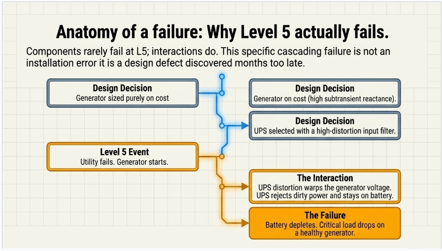
A UPS with a high-distortion input current characteristic, fed from a generator whose subtransient reactance was selected on cost, produces voltage distortion at the generator terminals that the UPS interprets as an unacceptable source. The UPS goes to battery on a healthy generator. Battery runs down. Load drops.
The failure occurs at L5 and its cause is a generator alternator selection and a UPS input filter decision made during design. It is not a commissioning defect; it is a design defect that commissioning found.
9. Where the L4 / L5 Boundary Actually Falls
Disputes about whether a given test belongs to Level 4 or Level 5 are common, and they are schedule disputes in disguise, because L5 requires full load bank deployment and the whole operations team while L4 does not. A workable boundary rule:
A test belongs to Level 4 if it exercises a single system and its own internal redundancy, with adjacent systems held in a normal state. A test belongs to Level 5 if its pass criterion depends on the response of a system other than the one being failed.
Under that rule, taking a UPS module offline and proving the remaining modules carry the load is Level 4. Failing the UPS and proving that the static switch transfers, the alternate path picks up, the EPMS raises the correct alarm, and the mechanical plant is unaffected is Level 5. Starting a generator on a manual signal is Level 3. Starting it on a real loss of utility with the transfer scheme live and the load real is Level 5.
Whatever boundary is chosen, it must be written into the commissioning plan before the schedule is baselined, and the load bank quantity, duration, and rental period must be derived from it. Load bank logistics are the long pole in most integrated testing programmes.
10. Designing for Testability
The following provisions cost very little at design and are difficult or impossible to add later. They are the practical output of taking commissioning seriously as an engineering discipline rather than a construction milestone.
- Permanent load bank connections with adequate capacity at the level of the distribution where load must be represented, not solely at the service entrance. Include the connection in the coordination study and the arc-flash analysis.
- Maintenance bypass around every device that must be serviced with the facility live, and a single-line diagram that makes each isolation sequence obvious.
- Test-position or drawout construction where breakers must be exercised without de-energising the bus.
- Metering and trending points sufficient to instrument the acceptance criteria: source-side and load-side of every transfer point, generator terminals, UPS input and output, and mechanical plant capacity points.
- Independent, redundant control power for protection and transfer schemes, and a defined behaviour on loss of control power. Control power is the single most common undocumented dependency in a facility that otherwise has no single points of failure.
- Written, complete sequences of operation issued as a design deliverable, not assembled by the controls contractor from equipment manuals.
- Generator sizing based on the step-load profile and the non-linear load characteristic, not steady-state kW alone, with the alternator and the UPS input characteristic evaluated together.
- Thermal ride-through capacity engineered explicitly — chilled water volume, thermal storage, or continuous cooling — with the target duration stated in the Basis of Design so that the L5 test has a pass criterion.
- Selective coordination demonstrated by study where required by code for emergency, legally required standby, or critical operations power systems, using devices whose settings are field-adjustable to the values the study requires.
- Grounding and bonding designed as a system across separately derived sources, transfer switches, and the white space, so that neutral switching arrangements and ground-fault sensing coordinate rather than conflict.
- Space, access, and temporary power provisions for the commissioning programme itself, including load bank staging, cable routing, and heat rejection during testing.
11. What Commissioning Actually Finds
The following defect classes recur across facilities, vendors, and geographies. They are listed by the level at which they are typically caught, which is usually later than the level at which they were introduced.
| Defect | Typically found at | Introduced at | Consequence if missed |
|---|---|---|---|
| Protective device settings not matching the current coordination study revision | L3 | Design or procurement | Unverified selectivity; a downstream fault takes out an upstream bus |
| CT ratio or polarity errors | L3 | Installation | Protection misoperation, false or absent metering data, failed differential schemes |
| Neutral switching and ground-fault sensing conflict across transfer switches and separately derived systems | L4 | Design | Nuisance ground-fault trips or, worse, a ground-fault system that will not sense a real fault |
| Generator unable to accept the specified block load, or unstable in parallel | L4 / L5 | Design (sizing) and factory testing scope | Failure of the primary resilience mechanism at the moment it is needed |
| UPS transferring to battery on generator source due to voltage distortion | L5 | Design (alternator and UPS input selection) | Battery depletion during an extended outage; complete load loss |
| Thermal ride-through shorter than the operational procedure assumes | L5 | Design (chilled water volume / continuous cooling) | Temperature excursion beyond the equipment envelope during a cooling event |
| Control power single point of failure | L5 | Design | A facility with full power redundancy that loses its transfer capability on one control power failure |
| Sequences of operation incomplete or contradictory between systems | L4 / L5 | Design | Untestable behaviour; controls contractor writes the sequence by default |
| Untorqued or improperly torqued bolted connections | L4 (thermography) | Installation | Progressive heating, connection failure, arcing fault in energised equipment |
| Battery string capacity below acceptance criteria | L3 | Manufacturing, storage, or commissioning delay | Autonomy shorter than the design basis; discovered during a real outage |
| Chiller staging instability at part load | L4 | Design and controls | Oscillating plant, poor efficiency, and unpredictable response to a real failure |
| Load bank connections absent or inadequate | L5 | Design | Expensive one-time testing; no practical means to re-test after future modifications |
12. Turnover, Training, and Ongoing Commissioning
The commissioning programme produces a facility and a body of evidence. The evidence has to survive the handover or it will be reconstructed, expensively, the first time the facility is modified.
- The systems manual: as-built single lines, sequences of operation as tested, setpoint schedules, the coordination study and the settings actually installed, and the arc-flash study aligned to the final configuration.
- The complete test record: L1 factory reports, L2 checklists including torque records, L3 start-up and settings verification, L4 functional test results, and L5 scenario results with the recorded data, not merely the pass/fail sheet.
- The issues log, closed out, with each finding traced to its resolution and re-test.
- Operator training conducted against the emergency operating procedures and the scenarios actually tested at L5, with the operations team present during the tests rather than briefed afterwards.
- Deferred and seasonal testing where design conditions could not be represented during the commissioning window — free cooling changeover being the usual example.
- A re-commissioning cadence, and a rule that any modification to the electrical or mechanical topology triggers re-analysis of the coordination and arc-flash studies and re-test of the affected scenarios. IT load growth changes the load profile the facility was proven at.
13. Reading the L1–L5 Chart Correctly
The widely circulated L1-to-L5 summaries communicate the sequence well. Five clarifications are worth stating because each has a design or contractual consequence.
Clarification 1 — The levels are a convention, not a standard
There is no published standard that defines L1 through L5 with fixed content. Process guidance exists in the commissioning standards and in data-center-specific best practice documents, but the level numbering itself is a project convention. It must be defined in the commissioning plan and referenced from the specifications, or the parties will discover their definitions differ at the point where it costs the most.
Clarification 2 — Level 0 belongs on the chart
Design-phase commissioning is where the cheapest findings are made and where the testability of the facility is determined. A chart that starts at the factory implies that commissioning begins when procurement ends, which is the framing that produces facilities that cannot pass their own integrated test.
Clarification 3 — The levels are per system, not per facility
Progression is not a single facility-wide march from L1 to L5. Each system advances at its own pace, and integrated testing gates on the slowest one. Schedule logic that treats the levels as facility-wide phases hides the actual critical path, which is usually one late-delivered switchboard or one incomplete controls integration.
Clarification 4 — The redundancy tests at L4 and L5 are different tests
Removing a redundant component and showing the system holds is a Level 4 activity. Failing a system and showing the rest of the facility responds correctly is Level 5. Charts that list "redundancy testing" at L4 and "UPS failure" at L5 without stating the distinction leave the boundary to be negotiated during execution.
Clarification 5 — There is a level after L5
Post-occupancy activity — seasonal testing, IT load migration verification, re-commissioning after modification, and ongoing commissioning against trended performance — is where the value of the programme is either preserved or lost. A facility proven once at handover and never re-proven is a facility whose resilience claim expires quietly.
14. Keentel Data Center Engineering Services
Keentel Engineering provides the electrical engineering that determines whether a data center can be commissioned successfully — the design work upstream of the test, and the technical support during it. Our data center practice covers the following.
14.1 Power Delivery and Interconnection
- Utility service planning and large-load interconnection: load characterisation, service capacity studies, coordination with the serving utility and, where applicable, the transmission provider and ISO or RTO large-load interconnection process.
- Point-of-interconnection engineering, substation design, and medium-voltage collection and distribution design for campus and multi-hall developments.
- On-site generation interconnection, including behind-the-meter generation, parallel operation, and export arrangements where the facility participates in grid programmes.
14.2 Facility Electrical Design
- Distribution topology development: N+1, 2N, 2(N+1), and block-redundant architectures evaluated against the availability and concurrent maintainability requirements in the OPR, with the maintenance and isolation sequences designed in rather than discovered later.
- Medium- and low-voltage distribution design, UPS and battery system design, generator plant design including paralleling schemes and fuel systems, and white-space power distribution.
- Grounding, bonding, and lightning protection design across separately derived sources, transfer equipment, and the white space.
14.3 Power System Studies
- Short-circuit, protective device coordination, and selective coordination studies where required for emergency, legally required standby, and critical operations power systems.
- Arc-flash incident energy analysis and labelling, with maintainability and equipment selection evaluated together rather than as a post-design compliance exercise.
- Load flow, motor starting, generator step-load and stability analysis, and harmonic and power quality studies, including the generator-to-UPS interaction that governs integrated test outcomes.
- Electromagnetic transient modelling where the interconnecting utility or the equipment configuration requires it.
14.4 Commissioning and Owner's Engineer Support
- Design-phase commissioning review: OPR and BOD verification, single-line review against the maintainability requirement, sequence-of-operation completeness, and testability provisions.
- Commissioning specification and plan development, level definitions, and acceptance criteria written to be measurable.
- Test script development traceable to the design basis, factory acceptance test procedure review and witnessing, and technical support during functional and integrated testing.
- Design review of EPC and contractor submittals, QA/QC of third-party design packages, and turnover documentation review.
Keentel Engineering holds a Florida Certificate of Authorization and maintains offices in Tampa, Austin, Sacramento, and Baltimore, supporting projects across the interconnections.
15. Frequently Asked Questions
Q1. Is L1 through L5 a standard?
No. It is a project convention. Formal process guidance exists in the building commissioning standards and in data-center-specific best-practice documents, but the level numbering is not codified anywhere. Define it explicitly in the commissioning plan and reference it from the specifications, because two parties can hold entirely reasonable but incompatible definitions of L4.
Q2. How does L1 through L5 relate to Uptime Institute Tiers?
They measure different things. Tier classification describes the facility's topology and capability — redundant components, multiple distribution paths, concurrent maintainability, fault tolerance. Commissioning levels describe the verification activities performed. A Tier II and a Tier IV facility both go through the same five levels; what differs is the scenario matrix at L5, which must prove the specific capability the topology claims.
Q3. And TIA-942 Rated levels?
A third and separate scheme, covering telecommunications, architectural, electrical, and mechanical criteria with its own conformity assessment path. The similar numbering to Uptime Tiers is a persistent source of confusion. Neither is a commissioning programme.
Q4. What is Level 0 and why is it not on most charts?
Level 0 is design-phase commissioning: verifying that the Owner's Project Requirements are measurable, that the Basis of Design addresses each requirement, that the single line supports the maintainability claim, that sequences of operation exist in testable form, and that testability provisions are in the design. It is missing from most charts because commissioning is culturally treated as a construction activity. It is the level with the highest return.
Q5. When should commissioning start?
At design. The commissioning agent should be engaged during design development, not at equipment delivery. Engaging at delivery means the programme can only find installation defects; the design defects have already been built.
Q6. What actually fails at integrated systems testing?
Interactions, not components. Individual equipment has usually been proven at L3 and L4. What fails at L5 is the relationship between systems: generator behaviour under a non-linear load, control power dependencies, transfer scheme timing against UPS ride-through, mechanical recovery time against thermal ride-through, and alarm and escalation logic that nobody tested end to end.
Q7. Why do generators pass factory testing and fail at L5?
Usually because the factory test did not represent the installed condition. Testing at unity power factor when the machine will run lagging, testing steady-state kW without the step-load profile, and testing with a linear load bank when the real load is a UPS with a distorting input current characteristic all produce a pass that does not predict field behaviour. The interaction between alternator subtransient reactance and UPS input distortion is the specific mechanism that most often surfaces at L5.
Q8. What is a black building test?
A complete loss of normal power with the facility restarted from a de-energised state. It is the most demanding scenario in the matrix because it exercises every assumption about what is available during a restart — control power, communications, sequencing logic, and the order in which loads can be picked up. Facilities that pass every other scenario sometimes fail this one.
Q9. What is thermal ride-through and why does it dominate the mechanical scenarios?
It is the time between loss of cooling and the point at which rack inlet temperature leaves the acceptable envelope. It is set by chilled water volume, thermal storage, and continuous cooling provisions, and it governs how much time the mechanical plant has to recover. Because it determines operational procedure, it must be stated as a target in the Basis of Design and measured at L5 rather than estimated.
Q10. How much load is required for integrated testing?
Full design load, represented on load banks distributed to reflect the design power and thermal profile. Testing at partial load or with load aggregated at one location proves the electrical path but not the air distribution, and it does not stress the thermal ride-through mechanism the way a real load does.
Q11. Where should load bank connections be provided?
At the distribution levels where load must be represented — typically PDU or RPP, not solely at the service entrance — and permanently, so that re-testing after future modification is practical. The connections should appear in the coordination study and the arc-flash analysis like any other load.
Q12. What is the practical rule for splitting L4 from L5?
A test is Level 4 if it exercises one system and its own internal redundancy with adjacent systems held normal. It is Level 5 if the pass criterion depends on the response of a different system. Removing a UPS module and proving the remaining modules hold is L4. Failing the UPS and proving the static switch, the alternate path, the alarm logic, and the mechanical plant all behave is L5.
Q13. How long does a commissioning programme take?
It depends on scope, but the useful planning insight is that the duration is driven by two things that are set early: the number of L5 scenarios and the load bank logistics required to support them. Both are determined by the OPR and the topology, so the schedule is effectively fixed during design even though it is executed at the end of construction.
Q14. Can commissioning be compressed if the schedule slips?
The levels that are compressed are always L2 and L5 — installation verification because it is checklist work with no visible product, and integrated testing because it is last. Both are the wrong choices. Compressing L2 puts unverified installations into service; compressing L5 means the resilience claim is untested. If compression is unavoidable, it should be a documented owner decision with the residual risk stated, not a quiet omission.
Q15. Who should write the test scripts?
Someone with access to the design intent, and traceably. Scripts written by the controls contractor from equipment manuals test what the equipment does, not what the design required. Scripts should reference the OPR requirement and the BOD decision they verify, so that the test record answers the question an owner will eventually ask: what evidence do we have that this facility meets the requirement we set?
Q16. What role should the design engineer play during commissioning?
Verifying that the settings installed at L3 match the current revision of the coordination study, reviewing functional test results against the design intent, participating in L5 scenario development, and resolving findings that turn out to be design issues rather than installation issues. The distinction matters commercially, and the design engineer is the only party positioned to make it credibly.
Q17. What is the most commonly falsified commissioning document?
Torque records. They are generated in volume, rarely audited, and the failure they prevent is invisible until it is not. Requiring calibrated tooling with calibration records, sample re-verification by an independent party, and thermographic survey under load at L4 gives three independent chances to catch what a signature alone will not.
Q18. What happens to the commissioning evidence after handover?
It becomes the systems manual and the baseline for every future modification. Any topology change should trigger re-analysis of the coordination and arc-flash studies and re-test of the affected scenarios. Facilities that lose this discipline drift: after several years of IT growth and equipment changes, the studies no longer describe the facility and the resilience claim rests on a test performed against a configuration that no longer exists.
Q19. Does high-density or liquid cooling change the programme?
It changes the mechanical scenario set substantially and shortens thermal ride-through, because the thermal mass per kilowatt is lower and the temperature excursion after a cooling loss is faster. It also introduces failure modes with no air-cooled analogue, including coolant distribution unit failure and leak detection and response. The electrical levels are largely unchanged; the L5 mechanical matrix is not.
Q20. What is the single highest-value change an owner can make to a commissioning programme?Q20. What is the single highest-value change an owner can make to a commissioning programme?
Move the commissioning agent upstream into design and require that every L5 scenario trace to a written, measurable requirement in the Owner's Project Requirements. That one change converts commissioning from a construction-phase inspection into a design discipline, and it is the difference between finding a problem when it costs drafting time and finding it when it costs the commissioning date.
Notice and Disclaimer
This document is original technical content prepared by Keentel Engineering LLC for general professional information. It is not project-specific engineering advice and does not constitute a design, a design review, a commissioning plan, or a certification for any particular facility. Commissioning level definitions described here are project conventions and vary between owners, commissioning authorities, and jurisdictions; the definitions written into a specific project's commissioning plan govern that project.
Code and standards references are provided by subject for orientation. The edition adopted by the authority having jurisdiction governs code requirements, and the current published edition of each standard governs its own requirements. Test methods, acceptance criteria, and equipment ratings must be taken from the applicable standard and the specific manufacturer's data for the equipment selected.
Keentel Engineering LLC is an independent engineering consultancy. Reference to any standard, code, certification scheme, industry organisation, or equipment category in this document does not imply affiliation with, endorsement by, or sponsorship from any such organisation, certification body, or manufacturer.

About the Author:
Sandip "Sonny" R. Patel, P.E.
IEEE Senior Member · Founder & CEO, Keentel Engineering
In 1995, Sonny Patel earned his Electrical Engineering degree from the University of Illinois. But degrees don't build legacies — action does.
For three decades, he has worked the power industry from every side of the table: 16 years as a utility engineer at Exelon/Commonwealth Edison; generation leadership across hydroelectric, industrial steam turbine, and a 9 GW renewable fleet; NERC Regional Entity Senior Compliance Engineer and Audit Team Lead, auditing some of the nation's largest utilities; and testing and commissioning lead on equipment up to 765 kV — the very top of the North American grid.Utility. Generator. Regulator. Consultant. Few engineers have seen all four seats. Fewer still have sat in them.
His experience spans nuclear, hydro, conventional generation, renewables, oil and gas, mining — and today's data centers, where he is authoring a three-book series on data center design. He is a Licensed Professional Engineer in six states and a Licensed Electrical Contractor in Florida (Unlimited EC) — he doesn't just design the work; he's qualified to stand behind its execution.Today, as Founder and CEO of Keentel Engineering, Sonny leads a nationwide team of engineers delivering substation design, power system studies, NERC compliance, and commissioning — done right, coast to coast.Three decades. Every side of the table. One standard: accountable engineering.
Services

Let's Discuss Your Project
Let's book a call to discuss your electrical engineering project that we can help you with.
About the Author:
Sandip "Sonny" R. Patel, P.E.
IEEE Senior Member · Founder & CEO, Keentel Engineering
In 1995, Sonny Patel earned his Electrical Engineering degree from the University of Illinois. But degrees don't build legacies — action does.
For three decades, he has worked the power industry from every side of the table: 16 years as a utility engineer at Exelon/Commonwealth Edison; generation leadership across hydroelectric, industrial steam turbine, and a 9 GW renewable fleet; NERC Regional Entity Senior Compliance Engineer and Audit Team Lead, auditing some of the nation's largest utilities; and testing and commissioning lead on equipment up to 765 kV — the very top of the North American grid.
Utility. Generator. Regulator. Consultant. Few engineers have seen all four seats. Fewer still have sat in them.
His experience spans nuclear, hydro, conventional generation, renewables, oil and gas, mining — and today's data centers, where he is authoring a three-book series on data center design. He is a Licensed Professional Engineer in six states and a Licensed Electrical Contractor in Florida (Unlimited EC) — he doesn't just design the work; he's qualified to stand behind its execution.
Today, as Founder and CEO of Keentel Engineering, Sonny leads a nationwide team of engineers delivering substation design, power system studies, NERC compliance, and commissioning — done right, coast to coast.Three decades. Every side of the table. One standard: accountable engineering.
Leave a Comment
Thank you for contacting us.
We will get back to you as soon as possible.
We will get back to you as soon as possible.
Oops, there was an error sending your message.
Please try again later.
Please try again later.
Related Posts

By SANDIP R PATEL
•
October 11, 2026
Explore grid inertia, RoCoF and frequency response, with swing equation calculations, frequency nadir analysis and US power system simulation examples.

By SANDIP R PATEL
•
October 10, 2026
Learn BESS DC sizing with power, energy, current and C-rate calculations, battery losses, degradation and a 100 MW/400 MWh utility-scale example.

By SANDIP R PATEL
•
October 10, 2026
Learn how BESS ROI is calculated using peak shaving, energy arbitrage, power quality and battery storage economics, with a practical 5 MW/10 MWh example.
By SANDIP R PATEL
•
October 10, 2026
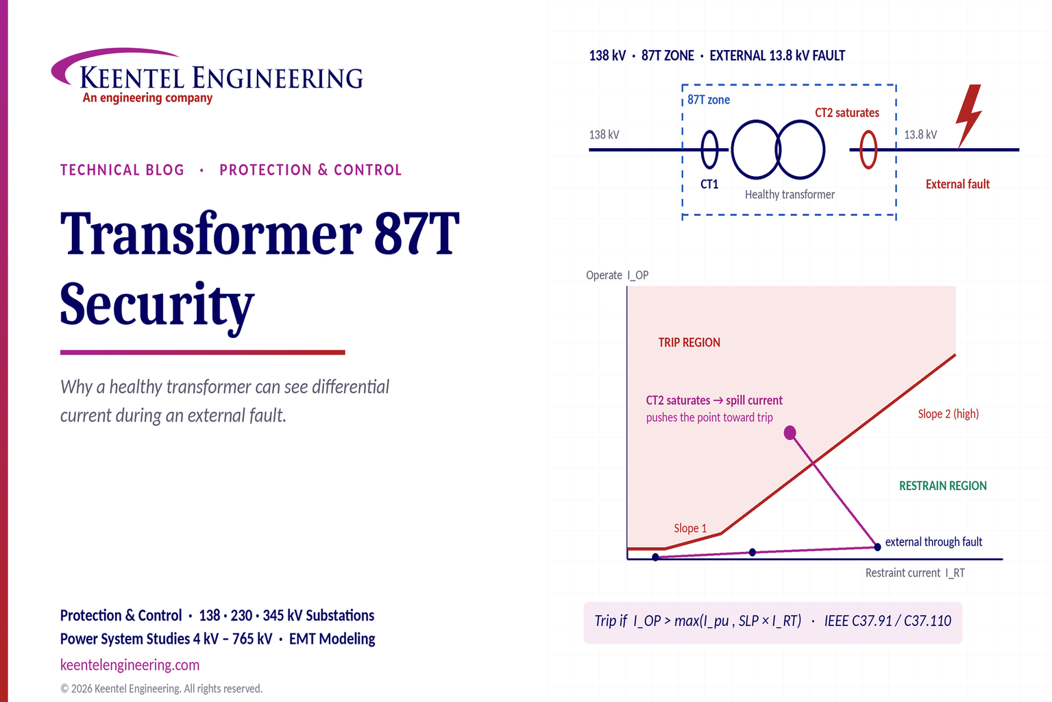
Learn why transformer differential relays detect current during external faults, how CT saturation causes spill current, and how secure 87T protection prevents trips.
By SANDIP R PATEL
•
October 10, 2026
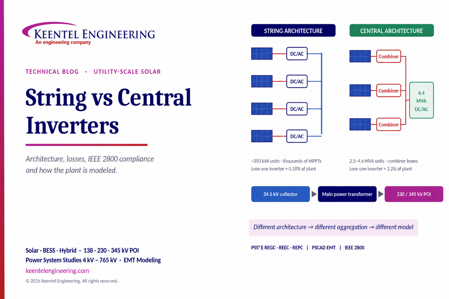
Compare string vs central inverters for utility-scale solar, including efficiency, maintenance, grid compliance, reactive power and interconnection studies.
By SANDIP R PATEL
•
October 9, 2026
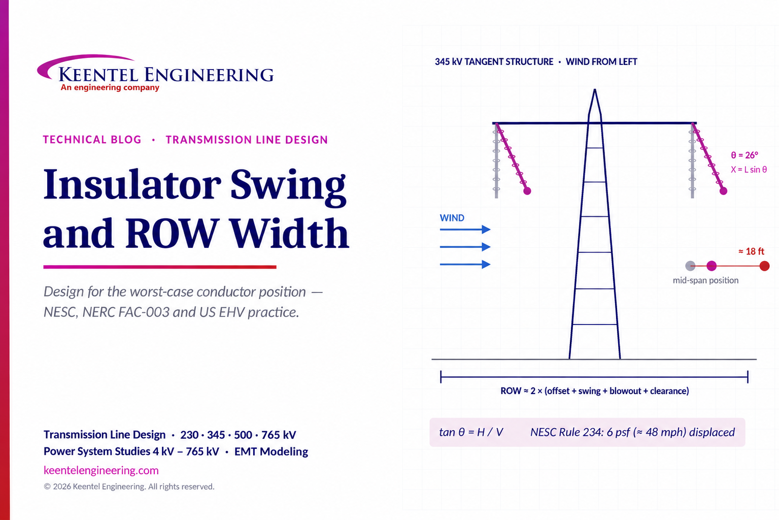
Learn how insulator swing angle and conductor blowout affect transmission line ROW width, with NESC clearances, NERC FAC-003 guidance, and a 345 kV example.
Copy

By SANDIP R PATEL
•
October 3, 2026
Engineering guide to PRC-028 disturbance recording, PRC-029 ride-through and PRC-030 event detection for inverter-based resources.

By SANDIP R PATEL
•
October 3, 2026
A practical guide to SSO classification, SSR, PEDI, Wind-SSCI, EMT analysis, mitigation and protection based on CIGRE TB 909.

By SANDIP R PATEL
•
October 3, 2026
Learn ERCOT generator testing for PFR, MOD-025 and MOD-026/027, including staged tests, capability verification, dynamic models and field testing.





