
A Coordinated Electric System Interconnection Review—the utility’s deep-dive on technical and cost impacts of your project.
Challenge: Frequent false tripping using conventional electromechanical relays
Solution: SEL-487E integration with multi-terminal differential protection and dynamic inrush restraint
Result: 90% reduction in false trips, saving over $250,000 in downtime
ERCOT enforces all of the above through simulation, which means your model is your compliance case. The bar is now high:
- Whole-facility scope. The model must represent everything the IT load, the UPS and power conversion, the cooling plant, the protection and control systems in formats compatible with ERCOT's study platforms (PSS/E, PSCAD, TSAT).
- Real control loops, not approximations. Generic textbook representations are unacceptable. The model must capture the actual inner control behavior of your power electronics.
- Hardware-validated converter models. For electronic loads, the PSCAD model must be benchmarked against actual hardware testing including voltage ride-through and subsynchronous response. A model assembled from standard PSCAD library blocks fails by definition, because a generic block has never been tested against your vendor's hardware. The good news: validation is a hardware-type test, so results for a given converter product are reusable across every facility that uses it.
- Format migration. Facilities that previously submitted the older composite load model (CMLD) format must transition to EPRI's PERC1 format.
- Three checkpoints. Models are reviewed before the stability study begins (no model, no study), before each quarterly stability assessment, and for electronic loads one final time before energization, when you must submit as-built models with a documented comparison against the previously studied data and a sworn attestation that the model matches actual field settings. ERCOT's review takes 10 business days, extendable by 20 put it on your critical path.
- A living obligation. Change your technology, controls, or relay settings in a way that affects ride-through including converting a crypto mining site to an AI data center — and you've triggered a new interconnection study, even if your megawatts don't change.
| Parameter | Detail |
|---|---|
| System | 230 kV / 138 kV transmission corridors, wind and wet-snow icing exposure |
| Data basis | 15 years of minute-resolution forced-outage records + regional weather observations |
| Core methods | Event grouping, MVA performance curves, time-to-95%-restore, area outage rate curves, fragility modeling, rerun-history benefits, exceedance and log-domain risk metrics |
| Headline result | ≈85% of maximum resilience benefit at 60% of original capital; worst-event restoration window cut from 11 days to 5 in rerun-history terms |
| Decision supported | Capital portfolio selection; resilience plan filing; post-investment verification framework |
| System / Topic | Governing Standard(s) | What It Controls |
|---|---|---|
| Overall plant electrical distribution | IEEE 141 (Red Book); IEEE 666 | Distribution architecture, voltage selection, design of generating station auxiliary service systems |
| Power system studies | IEEE 399 (Brown Book); IEEE 551 | Load flow, symmetrical/asymmetrical short circuit, motor starting methodologies down to the lowest LV panelboard |
| Protection & coordination | IEEE 242 (Buff Book); IEEE 3004.5; IEEE C37 series | Generator relaying (21, 59N, 87G), time-current coordination, selective clearing between LV and MV tiers |
| GSU / UAT / SST transformers | IEEE C57.12.00 and C57 family | Transformer ratings, impedance, testing, loading |
| HV switchyard breakers | IEEE C37.06 | AC high-voltage circuit breaker preferred ratings |
| MV switchgear (13.8 kV) | IEEE C37.20.2; IEEE C37.20.7 | Metal-clad construction, compartmentalization, vacuum breakers; arc-resistant design with plenum venting |
| MV cable | UL 1072; ICEA S-93-639 (NEMA WC 74) | Type MV-105 shielded cable, 133% insulation level for HRG systems |
| LV switchgear (480 V) | IEEE C37.13; UL 1558 | Metal-enclosed LV power circuit breaker switchgear to 635 V, draw-out ACBs with electronic trip units |
| Motor control centers | UL 845; NEMA ICS 18 | LV-MCC construction, MCCB/MCP protection for motors under ~200 HP |
| Motors | NEMA MG-1 | Motor performance, starting characteristics, service factors |
| DC & battery systems | IEEE 485; IEEE 946 | Lead-acid battery sizing (125/250 VDC), DC auxiliary system design |
| Grounding | IEEE 80; IEEE 142 (Green Book) | Ground grid step/touch potential limits; system grounding including high-resistance grounding |
| Lightning protection | IEEE 998 | Direct-stroke shielding of switchyard and outdoor generator structures |
| Arc flash & electrical safety | IEEE 1584; NFPA 70E | Incident energy calculation; worker safety boundaries and PPE |
| Fire protection | NFPA 850 | Fire protection and risk management for combustion turbine generating plants |
| Installation code | NEC (NFPA 70); NESC | Wiring methods inside the plant fence; overhead/outdoor clearances at the switchyard |
| Interconnection & compliance | FERC LGIP; NERC MOD-025/026/027, PRC-019/024/029, FAC-008 | Interconnection process, model validation, protection/ride-through coordination, facility ratings |
| IFC / Construction Deliverable | Purpose |
|---|---|
| Stamped IFC packages | Legal basis for construction; P.E. responsible charge |
| Final relay settings & TCCs | Protection as-installed matches the coordination study |
| Calculation archive | Owner records; NERC audit evidence trail |
| Commissioning procedures | Safe, sequenced energization; MOD field testing |
| Construction support | RFIs, field changes, FAT/SAT witness |
| As-builts & model handoff | Operating baseline; future study currency |
| Metric | Outcome |
|---|---|
| Defects found pre-occupancy | Three topology defects and one settings-mismatch family corrected before load migration; the shared-switchboard defect alone would have invalidated the concurrently-maintainable claim on day one |
| IST findings | Fourteen additional discrepancies surfaced under scenario testing (control logic, alarm mapping, one generator sequencing fault) — all closed before handover instead of during operations |
| Black-building test | Passed on second execution; the first attempt exposed the generator sequencing fault under true block load, exactly the failure the compressed plan would never have found |
| Handover quality | Operations team certified on the actual failure scenarios; corrected EOPs and settings documentation delivered as controlled documents |
| Business outcome | Occupancy proceeded three weeks behind the original date — against an independent estimate that the uncorrected sequencing fault carried a high probability of a full facility outage within the first year |
Part 2 — Frequently Asked Questions: Large Load Interconnection
An electric grid must remain in continuous balance — generation onto the grid must equal consumption from it at every instant. PJM achieves this balance, and prices it, through a layered market architecture. Each layer operates on a different time horizon, and each one touches project economics differently.
| Domain | Key Standards / Codes | What They Govern |
|---|---|---|
| Fire safety | NFPA 855; UL 9540 / UL 9540A | Installation requirements, separation, gas management; system safety listing and thermal-runaway fire testing |
| Grid interconnection | IEEE 1547 (distribution); IEEE 2800 (transmission IBRs) | Ride-through, reactive capability, power quality, and performance at the point of interconnection |
| Power quality | IEEE 519 | Harmonic distortion limits at the PCC |
| Protection & grounding | IEEE 80 / 81 / 142; C37 series | Grounding system design and testing; protective relaying |
| Reliability compliance | NERC standards (incl. PRC ride-through requirements) | Registered-entity obligations for grid-connected storage |
What a STATCOM Is Actually For
Aug 03, 2026 | Blog
The One Property That Justifies the Cost, Why Sizing Comes From Dynamic Studies Rather Than Load Flow, and the Design Decisions That Decide Whether It Helps or Hunts
1. Executive Summary
A STATCOM injects reactive power when voltage is low and absorbs it when voltage is high. That description is correct, it appears in every summary of the technology, and it explains nothing about why anyone buys one. Shunt capacitors and static var compensators do the same thing for less money.
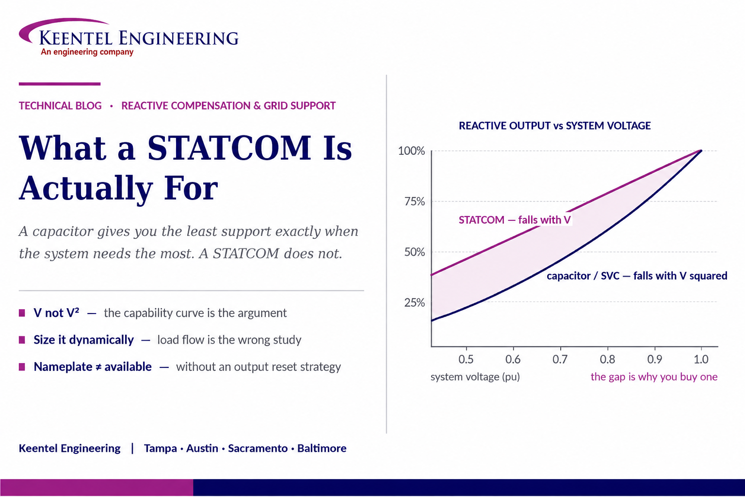
The property that justifies a STATCOM is how its capability behaves as voltage falls. A shunt capacitor produces reactive power proportional to the square of the applied voltage, so at eighty percent voltage it delivers about two thirds of its rating and at fifty percent about a quarter. A thyristor-based compensator behaves the same way for the same reason: it is switching impedances, and an impedance produces less current as voltage drops. A STATCOM is a voltage-source converter behind a reactance, and it can hold rated current down to low voltage. Its reactive output falls linearly with voltage rather than quadratically. At the moment the system is in trouble, it is delivering roughly twice what an equivalently rated capacitive device would.
That single characteristic is why STATCOMs appear where voltage stability margin, weak-grid interconnection, and fast disturbance recovery are the problem, and why they are hard to justify where the requirement is steady-state reactive supply. It also explains a design failure that recurs: a STATCOM sized from a load flow study, operating at or near its capacitive limit in the steady state, has almost no dynamic range left when the contingency arrives. The device is present, the nameplate is correct, and the capability is unavailable.
This paper works through what a STATCOM is at the converter level, the capability comparison against the alternatives, what it does not do, how sizing should actually be derived, droop and dynamic headroom, coordination with other voltage regulating equipment, weak-grid control interaction, the emerging grid-forming case, harmonics and resonance, the coupling transformer, protection, model and compliance obligations, and the practical engineering around losses, cooling and availability. It includes three illustrative case scenarios and a twenty-five question FAQ.
The sentence worth carrying out of this paper
A capacitor gives you the least support exactly when the system needs the most. A STATCOM does not.
Everything else about the technology is detail around that one fact — and if the application does not need that property, the application probably does not need a STATCOM.
2. What a STATCOM Actually Is
Strip away the packaging and a STATCOM is a controllable AC voltage source connected to the grid through a reactance — the leakage impedance of a coupling transformer, a series reactor, or both. A voltage-source converter with a DC-link capacitor synthesises that AC voltage; the DC link stores no useful energy for the grid, it simply provides the stiff DC rail the converter modulates against.
The reactive exchange follows directly from the two voltages across the reactance. If the converter’s internal voltage magnitude exceeds the grid voltage, current flows out of the converter into the system and the device is capacitive — it injects reactive power. If the internal voltage is lower, current flows the other way and the device is inductive. The quantity exchanged is set by the difference between the two magnitudes divided by the coupling reactance. A very small phase angle difference is also maintained, but only to draw the small real power needed to cover converter losses and keep the DC-link voltage regulated.
Two consequences follow that are worth stating plainly, because they explain most of the technology’s behaviour.
- The output is controlled by a voltage the converter creates, not by an impedance the system imposes. That is why the device can be commanded to full output at reduced system voltage.
- The output is bounded by converter current, not by admittance. The limit is a current limit, and it is set by the semiconductor devices and their cooling.
3. The Property That Justifies the Cost
Consider three devices all rated to deliver the same reactive power at nominal voltage, and ask what each delivers at reduced voltage.
A shunt capacitor is an admittance. Its current is proportional to voltage and its reactive output is proportional to voltage squared. At ninety percent voltage it delivers about eighty-one percent of rating; at eighty percent, about sixty-four; at fifty percent, about twenty-five.
A thyristor-based static var compensator switches and phase-controls impedances. Its capacitive branches are capacitors, so the same square-law behaviour applies. It is faster and continuously controllable, which is a real advantage, but it does not change the physics of what it is switching.
A STATCOM holds rated current as voltage falls, until either a control limit or the coupling reactance intervenes. Reactive output is the product of voltage and current, so with current held constant the output falls in proportion to voltage rather than to its square. At eighty percent voltage it delivers about eighty percent of rating rather than sixty-four; at fifty percent, about fifty rather than twenty-five.
That ratio grows exactly as conditions deteriorate, which is the entire argument. A voltage stability event is a positive feedback loop: voltage falls, reactive support falls faster than voltage, the deficit worsens, voltage falls further. A device whose support degrades linearly rather than quadratically damps that loop. A device whose support degrades quadratically participates in it.
Where this changes a decision
If the requirement is steady-state reactive supply at close to nominal voltage — power factor correction, flat voltage profile, transfer capability — mechanically switched capacitors are dramatically cheaper and the square law barely matters.
If the requirement is holding voltage through and after a disturbance, supporting a weak interconnection, or providing margin on a voltage stability limit, the square law is the whole problem and the STATCOM is the answer to it.
4. Comparing the Reactive Options
| Positive and negative sequence | Zero sequence | |
|---|---|---|
| What sets the magnitude | The converter current limit and its control priority logic | The transformer zero-sequence impedance, the neutral connection, and any neutral impedance |
| Typical order of magnitude at the point of interconnection | A small multiple of plant rated current, for a controlled duration | Governed by transformer impedance in the same way a conventional grounding source would be — frequently several times larger |
| Who decides it | The inverter manufacturer and the control configuration | The transformer specification, written during procurement |
| When it is fixed | Configurable, and changeable by firmware or settings | Fixed when the transformer is manufactured |
| How it behaves during the fault | Time-varying, control-dependent, and non-linear once the limiter saturates | A passive impedance path — predictable and stable |
| What it does to protection | Overcurrent may not reach pickup; sequence angle relationships are control outputs | Ground overcurrent may see substantial current; the plant becomes an infeed and a polarising source |
One combination deserves particular attention because it is often the economically correct answer: mechanically switched capacitors providing the bulk steady-state reactive requirement, with a STATCOM providing the dynamic range on top. The capacitors are cheap Mvar; the STATCOM is expensive Mvar that can be relied on during a disturbance. Making that combination work requires the control strategy described in Section 9.
5. Speed, and What It Is Measured Against
STATCOM response is usually quoted in the range of one to two cycles for the closed-loop voltage control, with the converter itself capable of changing current far faster than that. The number is meaningful only against what it is being compared to and what it is being asked to do.
Against mechanically switched equipment, which responds in seconds and in discrete steps, the difference is categorical. Against a thyristor-based compensator, which responds within a few cycles, the difference is real but modest — and speed alone would rarely justify the cost difference. The justification is the capability curve, not the response time; the response time is what makes the capability usable during a transient rather than only in the recovery.
For flicker mitigation the calculation is different again. Arc furnace and similar loads produce voltage fluctuation at frequencies where the human eye is most sensitive, and the compensator must track the disturbance rather than respond to it after the fact. There, converter response time and the ability to compensate unbalance phase-by-phase are the governing requirements, and they are the reason STATCOMs displaced earlier technologies in that application.
6. Topology and Rating
6.1 Converter Topology
Early STATCOMs used two-level and three-level converters with substantial output filtering and a step-up coupling transformer. Modern plant is predominantly modular — chains of cascaded submodules, each a small converter with its own capacitor, connected in series to synthesise a high-quality voltage waveform directly. The modular approach reduces harmonic filtering requirements substantially, allows redundant submodules so that a failure is bypassed rather than tripping the plant, and at medium voltage can permit direct connection without a coupling transformer.
The connection arrangement of a modular converter has an engineering consequence worth knowing. Chains connected in a delta arrangement can exchange energy between phases, which is what allows phase-by-phase unbalance compensation — the reason this arrangement dominates in arc furnace and unbalanced-load applications. Star-connected arrangements achieve unbalance capability by other means. If negative-sequence compensation is a requirement, it belongs in the specification, because it constrains the topology.
6.2 Rating Structure
A STATCOM rating is not one number. The specification should state the continuous capacitive and inductive ratings separately, since they are frequently asymmetric; the short-time overload capability with its duration, which is what actually carries the plant through a disturbance; the voltage range over which the continuous rating is maintained; and the ambient conditions at which all of it applies. A device that meets its rating at design ambient and derates at site ambient has a different capability than the one that was purchased.
7. What a STATCOM Does Not Do
Overstating capability is the fastest way to lose an argument with a system planner, and the popular summaries overstate it consistently.
- It does not supply real power. Aside from the small amount drawn to cover losses, a conventional STATCOM exchanges only reactive power. It cannot address a real power deficiency, and it cannot support frequency.
- It does not provide inertia. A conventional grid-following STATCOM has no inertial response and contributes nothing to rate-of-change-of-frequency behaviour. The grid-forming case in Section 12 changes this, and it is a different product with different requirements.
- It is not a fault current source. Its contribution is limited by converter current in the same way as any other inverter-based resource, which matters for protection as described in Section 15.
- It does not fix thermal limits. Where the binding constraint is conductor or equipment thermal capacity, reactive support relieves it only marginally through reduced current for the same real power transfer.
- It is not free to operate. Converter losses are real, they are paid for continuously, and they belong in the economic comparison against mechanically switched alternatives.
- It does not solve stability generally. It addresses voltage stability, and it can improve damping and transient stability margin through voltage support at the right location. It does not address angular or frequency stability directly.
8. Sizing: The Study That Governs
The most consequential decision in a STATCOM project is how much of it to buy, and the study that answers that question is not a load flow.
A load flow tells you the steady-state reactive requirement to hold a voltage target. That is a necessary input and it is almost never the governing one, because steady-state reactive supply is exactly the requirement that mechanically switched capacitors satisfy more cheaply. The dynamic requirement is what justifies the technology and what should set the rating.
- Voltage stability analysis — developing the relationship between reactive injection and voltage at the bus of interest, and between real power transfer and voltage — establishes the reactive margin available and how much additional dynamic support restores an acceptable margin under the governing contingency.
- Transient stability analysis establishes the behaviour during and immediately after the fault, including whether voltage recovers within the criteria the system operator applies and whether motor load or inverter-based generation would otherwise stall or disconnect.
- Contingency screening establishes which credible outage governs, which is frequently not the one intuition suggests, and whether the requirement is at one location or distributed.
- Where the driver is flicker or unbalance, the assessment is a measurement and simulation exercise against the applicable planning limits rather than a stability study.
Location matters as much as rating. Reactive support is a local commodity; injecting it at a strong bus achieves little, and injecting it at the electrically weak point achieves a great deal. The bus with convenient land and an available bay is often not that point, and a study that evaluates only the convenient location has not evaluated the problem.
9. Droop, Slope, and Dynamic Headroom
A STATCOM regulating voltage to a fixed setpoint with no droop will drive itself to a limit against any small persistent deviation and sit there. Once at a limit it has no dynamic capability at all, which is precisely the capability that was purchased.
The standard remedy is a droop, or slope, in the voltage-current characteristic: the device regulates to a target that moves slightly with its own output, so it settles at a partial output rather than driving to a limit. The slope value is a genuine engineering choice — too steep and the device provides little steady-state regulation, too shallow and it saturates and hunts against other voltage regulating equipment.
The second and more frequently missed provision is output reset. Where mechanically switched capacitors or reactors are available, a slow outer control loop should switch them so that the STATCOM output returns toward zero over minutes, restoring the full dynamic range in both directions. Without that loop, the switched equipment is deployed by an operator or by a simple voltage scheme, the STATCOM ends up holding a steady-state duty it was never meant to hold, and the plant enters every disturbance with most of its capability already spent. Case A in Section 18 is that failure.
The specification consequence
Require a susceptance or output regulator that coordinates the STATCOM with switched reactive equipment and returns the converter toward zero output in the steady state.
Then verify at commissioning that it actually does so under real system conditions, and trend the converter output afterwards. A STATCOM sitting at seventy percent capacitive output on an ordinary day is telling you something important.
10. Coordination With Other Voltage Controls
A STATCOM is rarely the only device regulating voltage in its area. On-load tap changers, generator excitation systems, other compensators, and increasingly the plant controllers of nearby inverter-based resources are all acting on the same quantity with different response times and different objectives.
The failure mode is hunting. A fast device corrects a deviation; a slower device with a different setpoint responds to the corrected condition and moves its own control; the fast device responds again. The result ranges from unnecessary tap changer operations and accelerated mechanism wear through to sustained voltage oscillation. It appears weeks or months after commissioning, under a load condition nobody tested.
The engineering answer is a deliberate hierarchy: the fast device takes the transient, the slow devices take the steady state, deadbands and time delays are set so that the slower device does not respond to a deviation the faster one is already correcting, and the setpoints are consistent. That requires knowing what the other devices are set to, which requires asking — including asking the utility about equipment on its side of the point of interconnection.
11. Weak Grids and Control Interaction
The most common modern application for a STATCOM is supporting an interconnection whose short-circuit strength is low relative to the inverter-based generation connected there. That application is also where the device is most likely to misbehave, because the same weakness that makes support valuable makes converter control stability harder.
As short-circuit strength falls relative to converter rating, the converter’s own current begins to move the voltage it is measuring. The phase-locked loop and the current controllers operate against a network impedance comparable to their own control impedance, stability margin erodes, and the failure mode is oscillatory rather than a gradual loss of performance. Where several converters share a weak interconnection — a wind or solar plant, a storage system, and a STATCOM, frequently from different manufacturers — they interact, and the aggregate behaviour is not predictable from any one of them alone.
Two engineering consequences follow. First, positive-sequence stability simulation cannot represent these phenomena, because they live at timescales and in control loops that the tools do not model. Electromagnetic transient analysis using manufacturers’ validated models, at the configurations actually deployed, is the only way to see them before commissioning. Second, control parameters are part of the design record: retuning a STATCOM controller in the field to solve a local problem can destabilise an interaction that was previously stable, and the change should trigger re-analysis rather than a settings note.
12. Grid-Forming STATCOM
The distinction between grid-following and grid-forming control applies to STATCOMs exactly as it does to generation converters, and it is where the technology is moving.
A grid-following STATCOM synchronises to a measured voltage and injects a controlled current. It needs a stable external voltage reference, and its performance degrades as the system providing that reference weakens — which is the awkward property discussed in Section 11.
A grid-forming STATCOM instead regulates voltage magnitude and angle behind a virtual impedance, presenting a voltage source to the network. The consequences are substantial: it can operate at very low system strength where grid-following control becomes unstable, it contributes to system strength rather than consuming it, it can provide a synthetic inertial response, and it can support voltage during and immediately after a fault in a way that assists nearby grid-following resources to ride through. Where a synchronous condenser would traditionally have been specified for system strength, a grid-forming STATCOM is increasingly the alternative under evaluation — without the short-circuit current contribution a rotating machine provides, which remains a genuine difference.
The trade-offs are real and should be examined rather than assumed away. Grid-forming operation imposes different current headroom requirements during transients, the control mode interacts with protection design, and interconnection requirements and model validation practice for grid-forming resources are still maturing. The decision belongs at specification stage, because it affects procurement, protection, and study scope.
13. Harmonics, Filters, and Resonance
A STATCOM is a converter, and adding one to a network adds everything discussed in the general literature on converter power quality. That is easy to forget when the device is being installed to improve power quality.
Modern modular converters produce far less low-order harmonic current than earlier topologies, and much of their switching content sits at frequencies well above the traditional harmonic measurement band. Both facts are advantages and neither eliminates the assessment. Current distortion at the point of common coupling is evaluated as total demand distortion against the applicable limits, and the assessment must consider what is already present rather than the STATCOM in isolation.
The larger risk is resonance. The converter’s output filter capacitance, any existing filter or power factor correction banks, and the distributed capacitance of medium-voltage cable together with system and transformer inductance form a network whose resonant frequencies may coincide with content the converter produces. The converter does not create the resonance; it excites one that already exists. The study that answers this is a frequency scan at the point of connection, run for each credible network configuration and each phase of build-out, and it is inexpensive at design stage and expensive afterwards.
Where a STATCOM replaces or supplements an existing static var compensator, the existing harmonic filters are part of the network the new converter sees. Their tuning was designed around the old plant, and the combination should be evaluated rather than assumed compatible.
14. The Coupling Transformer
Where a coupling transformer is used, it is not a commodity item and several of its parameters are design decisions with system consequences.
- Impedance. The coupling reactance is part of the control plant. Too low and the converter must be more precise in its voltage synthesis and sees higher fault current; too high and it consumes reactive capability and slows the effective response. It is selected with the converter, not independently.
- Winding connection and grounding. If the transformer presents a grounded-wye winding to the system, it is a zero-sequence source — a grounding bank that happens to have a converter behind it. That changes ground fault current distribution, affects the utility’s ground overcurrent coordination, and bears on effective grounding at the point of connection. It is a decision that should be taken deliberately and coordinated with the interconnecting utility, and its zero-sequence impedance should be a specified and tested quantity.
- Converter duty. The winding sees converter-generated harmonic content continuously, with the associated additional losses and heating. The specification should reflect converter service rather than assume conventional load duty.
- Tap changer interaction. Where the transformer has a tap changer, its control interacts with the converter’s voltage control and belongs in the coordination hierarchy of Section 10.
15. Protection and Fault Behaviour
A STATCOM presents the protection engineer with an inverter-based resource that produces no real power, and most of the consequences described for inverter-based generation carry across.
- Fault current contribution is limited by converter control to a small multiple of rated current, so overcurrent protection cannot rely on it and coordination studies must model it as a current-limited source rather than an equivalent machine.
- Negative-sequence behaviour depends on the control implementation and configuration. Where the device is specifically intended for unbalance compensation it will inject negative-sequence current deliberately, which is a further reason for protection elements relying on negative-sequence quantities to be evaluated rather than assumed.
- Zero-sequence contribution comes from the coupling transformer grounding, not from the converter, as Section 14 notes.
- The plant needs its own protection: converter and submodule protection, DC-link protection, coupling transformer differential and mechanical protections, overvoltage and overcurrent limits, and a defined behaviour on loss of control power or cooling.
- Ride-through obligations apply where the device falls within the applicable interconnection performance requirements, and protection settings must not defeat them. This makes protection settings and grid-code compliance the same conversation, exactly as it is for inverter-based generation.
- Behaviour after a fault matters as much as during it. How quickly the device returns to full output, and whether it overshoots, determines whether it assists or complicates the recovery.
16. Models, Compliance, and Verification
A STATCOM is a modelled element in every study the interconnecting entity performs, and the model obligations are the same class as those for inverter-based generation.
Positive-sequence models are required for load flow and stability work and must be in a form the planning process accepts. Electromagnetic transient models are required wherever control interaction, weak-grid behaviour, ride-through, or harmonic behaviour must be represented — and for a device whose whole purpose is fast dynamic response at a weak point, that is most of the interesting questions. Cross-validation between the two model types under large-signal disturbances is increasingly an explicit obligation rather than good practice.
Two procurement consequences follow. Model deliverables, their formats, and the right to use and share them with the transmission planner belong in the purchase specification, not in a request made after the order is placed. And because the models must represent the configuration actually deployed, control parameter changes made during commissioning trigger model updates. Verification against staged test data — step response testing with recorded oscillography, and comparison of measured against simulated behaviour — is what closes the loop, and it is the same evidence that demonstrates the device meets its specified performance.
17. Losses, Cooling, Availability, and Siting
The engineering that determines whether a STATCOM is a good asset over twenty years is unglamorous and is usually decided during procurement.
- Losses. Converter losses are continuous and are a material operating cost over the asset life. Loss evaluation should be part of the commercial comparison, at the duty the device will actually see rather than at full output.
- Cooling. Modern converters are typically liquid cooled, which introduces a system with pumps, heat exchangers, coolant chemistry, and its own failure modes. Cooling system availability is plant availability, and its redundancy should match the availability requirement placed on the STATCOM itself.
- Ambient derating. Rated capability at design ambient is not capability at site ambient. Confirm the rating at the actual extreme conditions, and confirm whether the extreme coincides with the system condition where the support is needed — in many climates it does.
- Redundancy. Modular converters allow redundant submodules with automatic bypass, so a submodule failure reduces headroom rather than tripping the plant. How many spares are provided, and at what point the plant must be taken out for replacement, is a specification decision.
- Availability and maintenance. The device is most valuable during system stress, so an outage schedule that coincides with peak season defeats the purpose. Maintenance access, spares strategy, and the manufacturer’s support model belong in the evaluation.
- Siting. Building or enclosure, noise, footprint, and access all follow from the topology selected, and they interact with the study conclusion about where the device should electrically be.
18. Case Studies
The following scenarios are composite and illustrative. They are constructed from patterns that recur across transmission, industrial, and renewable interconnection projects to show how these problems develop and how they are found. They do not describe any specific client, site, project, manufacturer, or utility.
18.1 Case A — The Dynamic Range That Was Already Spent
Situation. A STATCOM was installed at a substation to provide dynamic voltage support for a contingency identified in planning studies. Sizing had been derived from a load flow case establishing the reactive requirement to hold the voltage target. The plant was commissioned, met its acceptance tests, and operated without complaint.
What the review found. In normal operation the converter sat at roughly seventy to eighty percent of its capacitive rating, because it was supplying steady-state reactive demand that nothing else was supplying. There was no outer loop switching the available mechanically switched capacitors to return the converter toward zero output, and the voltage control had insufficient droop to prevent it settling near a limit. For the contingency it had been purchased to cover, the dynamic capability actually available was a fraction of the nameplate.
Exposure. The planning studies that justified the installation assumed full dynamic range. The system therefore had materially less voltage stability margin than the models represented, and the shortfall would only have been discovered during the contingency.
Remedy. A susceptance regulator was implemented to switch the capacitor banks and return the converter output toward zero over a several-minute time constant, with the droop reset to a value coordinated against the other voltage regulating equipment in the area. Converter output was trended afterwards to confirm the steady-state operating point, and the planning model was updated to represent the control strategy rather than an idealised device.
Lesson. Nameplate rating is not available capability. A STATCOM holding a steady-state duty has spent the asset before the event arrives. Specify the output reset strategy, verify it at commissioning under real system conditions, and trend the operating point in service — a converter sitting at high steady-state output is reporting a design problem.
18.2 Case B — The Oscillation That Only Appeared in the Time Domain
Situation. A STATCOM was added at a point of interconnection serving a renewable plant, to satisfy a dynamic reactive requirement in the interconnection agreement. Positive-sequence load flow and stability studies were performed, the results were acceptable, and the equipment was procured and installed. Another inverter-based plant from a different manufacturer connected nearby during the same period.
What the review found. System strength at the interconnection was low relative to the aggregate converter rating once all resources were considered together. Electromagnetic transient simulation, performed after unexplained oscillatory behaviour appeared during a low-load period, reproduced a sustained interaction between the STATCOM controller and the neighbouring plant controller at a frequency the positive-sequence tools could not represent. Neither device exhibited the behaviour in isolation.
Exposure. Sustained oscillation on the interconnection, with the associated equipment stress and the prospect of protective operation. The studies of record did not predict it and could not have, given the tools used.
Remedy. Manufacturers’ validated electromagnetic transient models were obtained for both devices at their deployed configurations, the interaction was reproduced and the sensitivity to controller parameters established, and coordinated retuning was implemented and verified in simulation before field application. Control parameters were placed under configuration control, with a requirement that any change trigger re-analysis.
Lesson. A STATCOM at a weak interconnection is a converter added to a population of converters. Aggregate system strength governs, positive-sequence tools cannot see the failure mode, and electromagnetic transient analysis with validated manufacturer models is a requirement rather than a refinement.
18.3 Case C — The Resonance the New Converter Excited
Situation. A STATCOM was installed at an industrial site to address voltage fluctuation from a variable load. The site already had power factor correction capacitors with detuning reactors, installed years earlier, and an extensive medium-voltage cable system serving the plant.
What the review found. A frequency scan performed after capacitor bank fuses began operating showed a parallel resonance close to a frequency present in the STATCOM’s output spectrum. The resonance was a property of the existing capacitors, the cable capacitance, and the supply transformer inductance; it had existed before the STATCOM arrived and nothing had previously excited it at that frequency. Distortion measurements at the point of common coupling showed the resulting voltage distortion approaching the applicable limit.
Exposure. Capacitor and reactor thermal stress with progressive failure, fuse operations reducing the reactive support the plant depended on, and a power quality position at the point of common coupling that would not have survived a utility investigation.
Remedy. The detuning arrangement of the existing capacitor banks was re-evaluated and modified against the scan so that the resonance moved away from the excited frequency, converter filtering was reviewed with the manufacturer, and the scan was repeated for each plant configuration including future expansion. Post-modification measurement at the point of common coupling confirmed compliance.
Lesson.
A device installed to improve power quality is itself a converter. Run a frequency scan before installation, for every network configuration and build phase, and treat existing capacitor banks and cable capacitance as part of the network the new converter will excite — not as pre-existing equipment that can be left unexamined.
19. Reading the Graphic Correctly
The reason it beats a capacitor is missing
Injecting reactive power at low voltage and absorbing at high voltage describes every reactive compensation device ever built. The distinguishing property — that a STATCOM holds rated current and therefore loses capability linearly with voltage rather than quadratically — is the whole commercial argument and it rarely appears in these summaries.
"Grid stability" is doing too much work
A STATCOM addresses voltage stability and can improve damping and transient stability margin through well-located voltage support. It does not address frequency stability, provides no inertia in its conventional form, and supplies no real power. Presenting it as a general stability solution invites a planner to ask a question the summary cannot answer.
Nameplate is not available capability
The diagrams show a device with its full range available at the moment of the disturbance. Whether that is true depends on droop, on coordination with switched reactive equipment, and on whether an output reset strategy exists. Case A is what happens when it does not.
It is a converter too
The graphic frames the device as a solution to power quality problems. It is also a source of them: harmonic content, a filter capacitance that participates in network resonance, and control dynamics that can interact with other converters at a weak point. Those belong in the same conversation.
The grid-forming distinction is not mentioned
It is the most consequential development in this technology. A grid-forming STATCOM contributes to system strength and can provide a synthetic inertial response; a grid-following one does not. Treating them as the same product produces the wrong specification.
20. Keentel Electrical Power Engineering Services
Keentel Engineering supports reactive compensation projects across the full arc — from establishing whether the requirement is genuinely dynamic, through sizing, specification and interconnection, to commissioning verification and model validation.
20.1 Studies That Establish the Requirement
- Voltage stability analysis, reactive margin assessment, and contingency screening to establish whether the requirement is steady-state or dynamic, how much is needed, and where it should electrically be located.
- Transient stability analysis including voltage recovery criteria, motor and inverter-based load behaviour, and the interaction between compensation and ride-through obligations.
- Grid strength assessment and weak-grid evaluation for interconnections with significant inverter-based capacity.
- Flicker and unbalance assessment against the applicable planning limits, where the driver is a fluctuating or unbalanced load.
- Economic comparison of mechanically switched, thyristor-based, converter-based, and hybrid solutions against the requirement actually established.
20.2 Design, Specification, and Interconnection
- Technical specification development covering rating structure, capability versus voltage, overload duration, unbalance capability, control modes, droop and output reset strategy, model deliverables, and factory and site test scope.
- Coupling transformer specification including impedance, winding connection and grounding, zero-sequence impedance requirements and test scope, and converter duty.
- Point-of-interconnection engineering, substation design, and interconnection application and study-phase technical support.
- Voltage control coordination design across the STATCOM, switched reactive equipment, tap changers, generator excitation, and neighbouring plant controllers.
20.3 Power Quality and Transient Analysis
- Harmonic frequency scan and injection studies across network configurations and build phases, with compliance assessed at the correct point using the correct metric.
- Electromagnetic transient modelling for control interaction, weak-grid stability, ride-through verification, switching and overvoltage transients, and fault-response behaviour at protection timescales.
- Short-circuit, protective coordination, and arc-flash studies with converter-based devices represented as current-limited sources.
- Effective grounding and ground fault overvoltage assessment where the coupling transformer introduces a zero-sequence source.
20.4 Commissioning, Verification, and Compliance
- Commissioning specification and test procedures including step-response testing, capability verification across the voltage range, and control coordination verification under real system conditions.
- Model verification and validation against staged test data and disturbance records, and cross-validation between positive-sequence and electromagnetic transient models.
- NERC compliance support including voltage schedule obligations, protection and control coordination, model verification, and the ride-through and disturbance monitoring requirements applicable to inverter-based resources.
- Design review of EPC and vendor submittals, QA/QC of third-party study packages, and performance investigation where an installed device is not behaving as specified.
Keentel Engineering holds a Florida Certificate of Authorization and maintains offices in Tampa, Austin, Sacramento, and Baltimore, supporting projects across the interconnections.
21. Frequently Asked Questions
A controllable AC voltage source — a voltage-source converter with a DC-link capacitor — connected to the grid through a reactance, which exchanges reactive power according to the difference between its internal voltage magnitude and the grid voltage.
By the voltage magnitude it synthesises relative to the grid. Higher than the grid and current flows outward, so the device is capacitive and injects reactive power. Lower and it is inductive and absorbs. A small angle difference is also maintained, but only to draw the real power that covers converter losses and holds the DC-link voltage.
For steady-state reactive supply at close to nominal voltage, you probably should — they are far cheaper. The reason to buy a STATCOM is how capability behaves as voltage falls, which is the subject of the next answer.
A capacitor is an admittance, so its reactive output falls with the square of voltage — about sixty-four percent of rating at eighty percent voltage, about twenty-five percent at half voltage. A STATCOM holds rated current, so its output falls in proportion to voltage — about eighty percent at eighty percent voltage. The advantage grows exactly as conditions deteriorate, which is when it matters.
No. A thyristor-based compensator switches and phase-controls impedances, and its capacitive branches are capacitors, so the square-law behaviour applies. It is fast and continuously controllable, which is a genuine advantage over mechanically switched equipment, but it does not change the physics of what it is switching.
Typically one to two cycles for closed-loop voltage control, with the converter able to change current faster still. Against mechanically switched equipment responding in seconds the difference is categorical; against a thyristor-based compensator responding in a few cycles it is modest. Speed alone rarely justifies the cost — the capability curve does.
A conventional one provides neither. It exchanges only reactive power aside from its own losses, and a grid-following device has no inertial response. Adding energy storage gives real power capability; grid-forming control gives a synthetic inertial response. Both are different products with different specifications.
No more than any other inverter-based resource. Its contribution is limited by converter control to a small multiple of rated current, so protection coordination must model it as a current-limited source rather than an equivalent machine.
Not a load flow. A load flow establishes the steady-state reactive requirement, which is the requirement mechanically switched capacitors satisfy more cheaply. The dynamic requirement should set the rating, and it comes from voltage stability analysis, reactive margin assessment, transient stability analysis, and contingency screening.
Often more. Reactive support is a local commodity; injecting at a strong bus achieves little and injecting at the electrically weak point achieves a great deal. The bus with convenient land and a spare bay is frequently not that point, and a study that evaluates only the convenient location has not evaluated the problem.
A deliberate relationship between the voltage setpoint and the device’s own output, so it settles at a partial output rather than driving to a limit against any small persistent deviation. Without it the device saturates and has no dynamic capability left. Too steep and it provides little steady-state regulation; too shallow and it saturates and hunts against other voltage controls.
A slow outer loop that switches mechanically switched capacitors or reactors so the converter returns toward zero output over minutes, restoring full dynamic range in both directions. Without it the device ends up holding a steady-state duty and enters every disturbance with most of its capability already spent — which is the failure in Case A.
Trend the converter output under normal conditions. A device sitting at a high steady-state capacitive or inductive output on an ordinary day is reporting that its dynamic range is largely unavailable, and that the planning studies assuming full range are optimistic.
Uncoordinated voltage controls. Tap changers, generator excitation, other compensators, and neighbouring plant controllers all act on the same quantity at different speeds. Without a deliberate hierarchy — fast device takes the transient, slow devices take the steady state, deadbands and delays set so the slow device does not chase a correction already underway — they chase each other.
Because that is where dynamic voltage support is most valuable. It is also where the device is most likely to misbehave: as system strength falls relative to converter rating, the converter’s own current moves the voltage it measures, control stability margin erodes, and the failure mode is oscillatory. The application and the risk arrive together.
Because positive-sequence stability tools cannot represent converter control dynamics at the timescales where interaction occurs. Where several converters from different manufacturers share a weak interconnection, the aggregate behaviour is not predictable from any one in isolation, and only time-domain simulation with validated manufacturer models will reveal it before commissioning.
One that regulates voltage magnitude and angle behind a virtual impedance rather than injecting current against a measured voltage. It can operate at very low system strength, contributes to system strength rather than consuming it, and can provide a synthetic inertial response. It is increasingly evaluated where a synchronous condenser would once have been specified — though it does not provide the short-circuit current a rotating machine does.
Yes, and it is easy to forget because the device is often installed to improve power quality. It is a converter: it injects harmonic current, its output filter capacitance participates in network resonance, and its controls can interact with other converters. Assess current distortion at the point of common coupling, and run a frequency scan.
The converter does not create resonance; it excites one the network already has. Filter and power factor correction capacitance, medium-voltage cable capacitance, and system and transformer inductance together define resonant frequencies that may coincide with content the converter produces. A frequency scan at the point of connection, for each network configuration and build phase, is the study that answers it.
Considerably. A grounded-wye winding facing the system makes the installation a zero-sequence source — effectively a grounding bank with a converter behind it — which changes ground fault current distribution, affects the utility’s ground overcurrent coordination, and bears on effective grounding. Its zero-sequence impedance should be a specified and tested quantity, and the arrangement should be coordinated with the utility.
For dynamic reactive support, generally yes and with faster response. For short-circuit current contribution, no — a converter is current-limited and a rotating machine is not. For inertia and system strength, a grid-forming STATCOM addresses much of the gap without providing fault current. The right comparison depends on which of those properties the system actually needs.
Converter losses are continuous and material over the asset life, and they belong in the commercial comparison at the duty the device will actually see rather than at full output. Cooling systems add their own auxiliary load and their own availability considerations.
Capability versus voltage rather than a single Mvar number; separate continuous capacitive and inductive ratings; short-time overload magnitude and duration; the ambient conditions at which the ratings apply; unbalance compensation capability where required, since it constrains topology; droop and output reset strategy; redundancy and bypass provisions; loss evaluation basis; and model deliverables with usage rights.
Capability across the voltage range rather than at nominal only; step response against the specified dynamics; the droop and output reset behaviour under real system conditions rather than in a test mode; coordination with other voltage regulating equipment; harmonic performance measured at the point of common coupling against a pre-energisation baseline; and model verification against the recorded response.
Establish whether the requirement is genuinely dynamic before selecting the technology, and if it is, size it from the dynamic study and specify the output reset strategy that keeps the capability available. Most disappointing STATCOM installations are not badly built — they are correctly built against a requirement that was never properly established, or they are holding a steady-state duty that has quietly consumed the capability that justified the purchase.
References and Further Reading
The following are referenced by subject in the body of this document. The current published edition of each standard governs its own requirements, and the interconnecting entity’s published requirements govern any project decision.
Compensation and Application
- IEEE Std 1031, Guide for the Functional Specification of Transmission Static Var Compensators, and IEEE Std 1303, Guide for Static Var Compensator Field Testing — the specification and test framework from which converter-based compensator practice largely derives — IEEE Standards Association
https://standards.ieee.org/ - IEEE Std 1204, Guide for Planning DC Links Terminating at AC Locations Having Low Short-Circuit Capacities — the foundational treatment of converter behaviour at low system strength — IEEE Standards Association
https://standards.ieee.org/ - CIGRE technical brochures on static synchronous compensators, converter-based reactive compensation, and grid-forming converter technology — CIGRE
https://www.cigre.org/
Power Quality
- IEEE Std 519, Standard for Harmonic Control in Electric Power Systems — the total demand distortion framework applied at the point of common coupling — IEEE Standards Association
https://standards.ieee.org/ieee/519/10677/ - IEEE Std 1453, Recommended Practice for the Analysis of Fluctuating Installations on Power Systems, and IEC 61000-3-7, Assessment of emission limits for fluctuating installations — the flicker framework relevant to arc furnace and similar applications — IEEE Standards Association and IEC
https://standards.ieee.org/ - IEEE Std 3002.8, Recommended Practice for Conducting Harmonic Studies and Analysis of Industrial and Commercial Power Systems, and IEEE Std 1159, Recommended Practice for Monitoring Electric Power Quality — IEEE Standards Association
https://standards.ieee.org/
Interconnection, Transformers, and Compliance
- IEEE Std 2800, Standard for Interconnection and Interoperability of Inverter-Based Resources Interconnecting with Associated Transmission Electric Power Systems — including reactive capability, voltage control and ride-through requirements — IEEE Standards Association
https://standards.ieee.org/ieee/2800/10453/ - IEEE Std 1547, Standard for Interconnection and Interoperability of Distributed Energy Resources with Associated Electric Power Systems Interfaces, where the installation is distribution-connected — IEEE Standards Association
https://standards.ieee.org/ - IEEE Std C57.12.00 and C57.12.90 for transformer requirements and test code, and IEEE Std C57.129 for converter-duty transformer application — IEEE Standards Association
https://standards.ieee.org/ - IEEE Std C62.92 series on neutral grounding, relevant where the coupling transformer introduces a zero-sequence source at the point of connection — IEEE Standards Association
https://standards.ieee.org/ - NERC Reliability Standards — including voltage and reactive control obligations, protection and control coordination, model verification and validation, and the ride-through and disturbance monitoring requirements applicable to inverter-based resources — North American Electric Reliability Corporation
https://www.nerc.com/pa/Stand/Pages/ReliabilityStandards.aspx
Notice and Disclaimer
This document is original technical content prepared by Keentel Engineering LLC for general professional information. It is not project-specific engineering advice and does not constitute a study, a design, an equipment specification, or a compliance determination for any installation. Compensation technology selection, rating, location, and control strategy must be established by project-specific analysis using verified system and equipment data and must satisfy the interconnecting entity’s published requirements.
Capability relationships, response times, and comparative characteristics described here are general engineering discussion used to demonstrate the principles involved. Actual performance varies by manufacturer, topology, rating structure, control implementation, and site conditions, and must be taken from the specific manufacturer data for the equipment under consideration.
The case studies in Section 18 are composite and illustrative. They are constructed from patterns that recur across the industry to demonstrate how these problems develop and how they are found. They do not describe any specific client, site, project, manufacturer, or utility, and no inference should be drawn about any actual installation or party.
Keentel Engineering LLC is an independent engineering consultancy. Reference to any standard, industry organisation, regulator, utility, or equipment category in this document does not imply affiliation with, endorsement by, or sponsorship from any such organisation or manufacturer.

About the Author:
Sandip "Sonny" R. Patel, P.E.
IEEE Senior Member · Founder & CEO, Keentel Engineering
In 1995, Sonny Patel earned his Electrical Engineering degree from the University of Illinois. But degrees don't build legacies — action does.
For three decades, he has worked the power industry from every side of the table: 16 years as a utility engineer at Exelon/Commonwealth Edison; generation leadership across hydroelectric, industrial steam turbine, and a 9 GW renewable fleet; NERC Regional Entity Senior Compliance Engineer and Audit Team Lead, auditing some of the nation's largest utilities; and testing and commissioning lead on equipment up to 765 kV — the very top of the North American grid.
Utility. Generator. Regulator. Consultant. Few engineers have seen all four seats. Fewer still have sat in them.His experience spans nuclear, hydro, conventional generation, renewables, oil and gas, mining — and today's data centers, where he is authoring a three-book series on data center design. He is a Licensed Professional Engineer in six states and a Licensed Electrical Contractor in Florida (Unlimited EC) — he doesn't just design the work; he's qualified to stand behind its execution.Today, as Founder and CEO of Keentel Engineering, Sonny leads 51 engineers delivering substation design, power system studies, NERC compliance, and commissioning — done right, coast to coast.Three decades. Every side of the table. One standard: accountable engineering
Services

Let's Discuss Your Project
Let's book a call to discuss your electrical engineering project that we can help you with.
About the Author:
Sandip "Sonny" R. Patel, P.E.
IEEE Senior Member · Founder & CEO, Keentel Engineering
In 1995, Sonny Patel earned his Electrical Engineering degree from the University of Illinois. But degrees don't build legacies — action does.
For three decades, he has worked the power industry from every side of the table: 16 years as a utility engineer at Exelon/Commonwealth Edison; generation leadership across hydroelectric, industrial steam turbine, and a 9 GW renewable fleet; NERC Regional Entity Senior Compliance Engineer and Audit Team Lead, auditing some of the nation's largest utilities; and testing and commissioning lead on equipment up to 765 kV — the very top of the North American grid.Utility. Generator. Regulator. Consultant. Few engineers have seen all four seats. Fewer still have sat in them.His experience spans nuclear, hydro, conventional generation, renewables, oil and gas, mining — and today's data centers, where he is authoring a three-book series on data center design. He is a Licensed Professional Engineer in six states and a Licensed Electrical Contractor in Florida (Unlimited EC) — he doesn't just design the work; he's qualified to stand behind its execution.Today, as Founder and CEO of Keentel Engineering, Sonny leads 51 engineers delivering substation design, power system studies, NERC compliance, and commissioning — done right, coast to coast.Three decades. Every side of the table. One standard: accountable engineering
Leave a Comment
Thank you for contacting us.
We will get back to you as soon as possible.
We will get back to you as soon as possible.
Oops, there was an error sending your message.
Please try again later.
Please try again later.
Related Posts
By SANDIP R PATEL
•
September 1, 2026
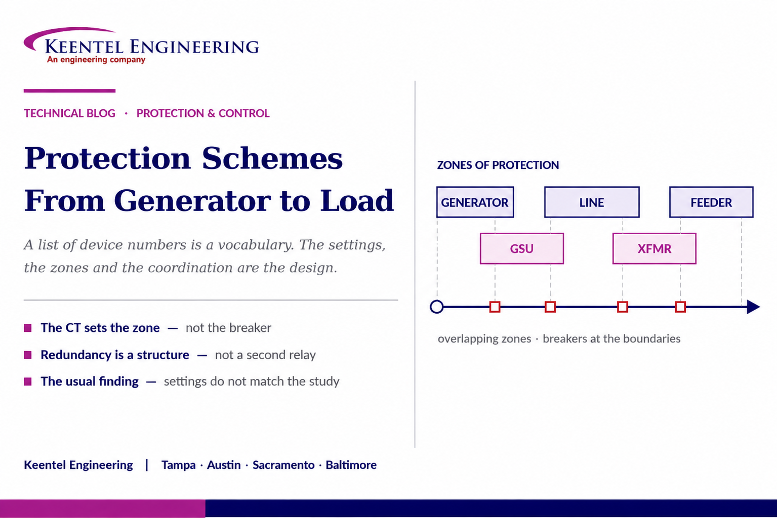
Learn power system protection schemes from generator to load, including protection zones, relay coordination, device numbers, backup protection, and settings.
By SANDIP R PATEL
•
September 1, 2026
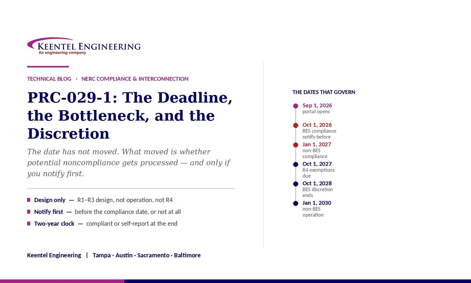
Understand PRC-029-1 compliance deadlines, IBR ride-through requirements, R1–R4, enforcement discretion, notification rules, and owner action steps.
By SANDIP R PATEL
•
September 1, 2026
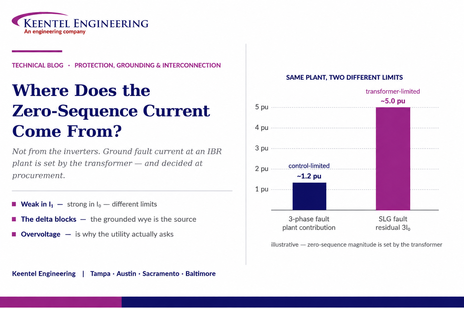
Learn where zero-sequence current comes from in inverter-based plants and how transformer grounding affects ground faults, overvoltage, protection, and interconnection.
By SANDIP R PATEL
•
August 31, 2026
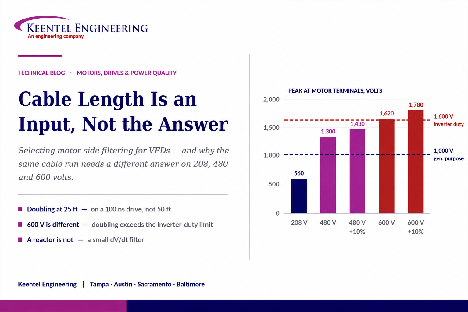
Learn how VFD cable length, voltage class, reflected wave and motor insulation determine when to use an output reactor, dV/dt filter or sine-wave filter.
By SANDIP R PATEL
•
August 29, 2026
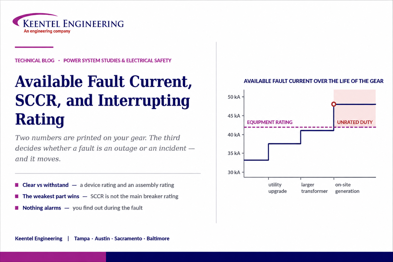
Learn how available fault current, SCCR and interrupting ratings affect equipment safety, short-circuit studies, arc flash risk and electrical system design.
By SANDIP R PATEL
•
August 29, 2026
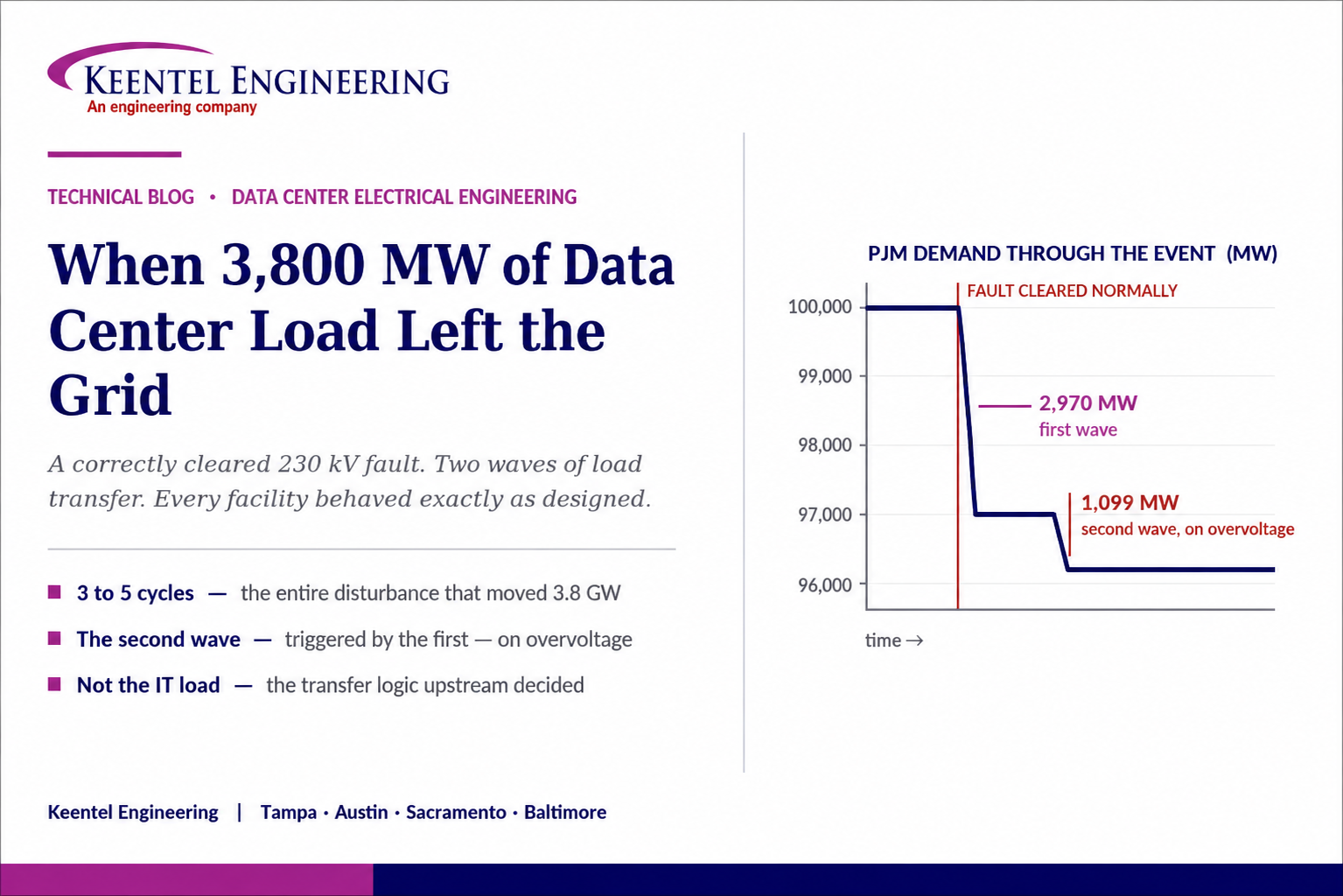
Explore the 3,800 MW data center load event, why a cleared 230 kV fault triggered load transfers, and what it means for ride-through and grid reliability.
By SANDIP R PATEL
•
August 28, 2026
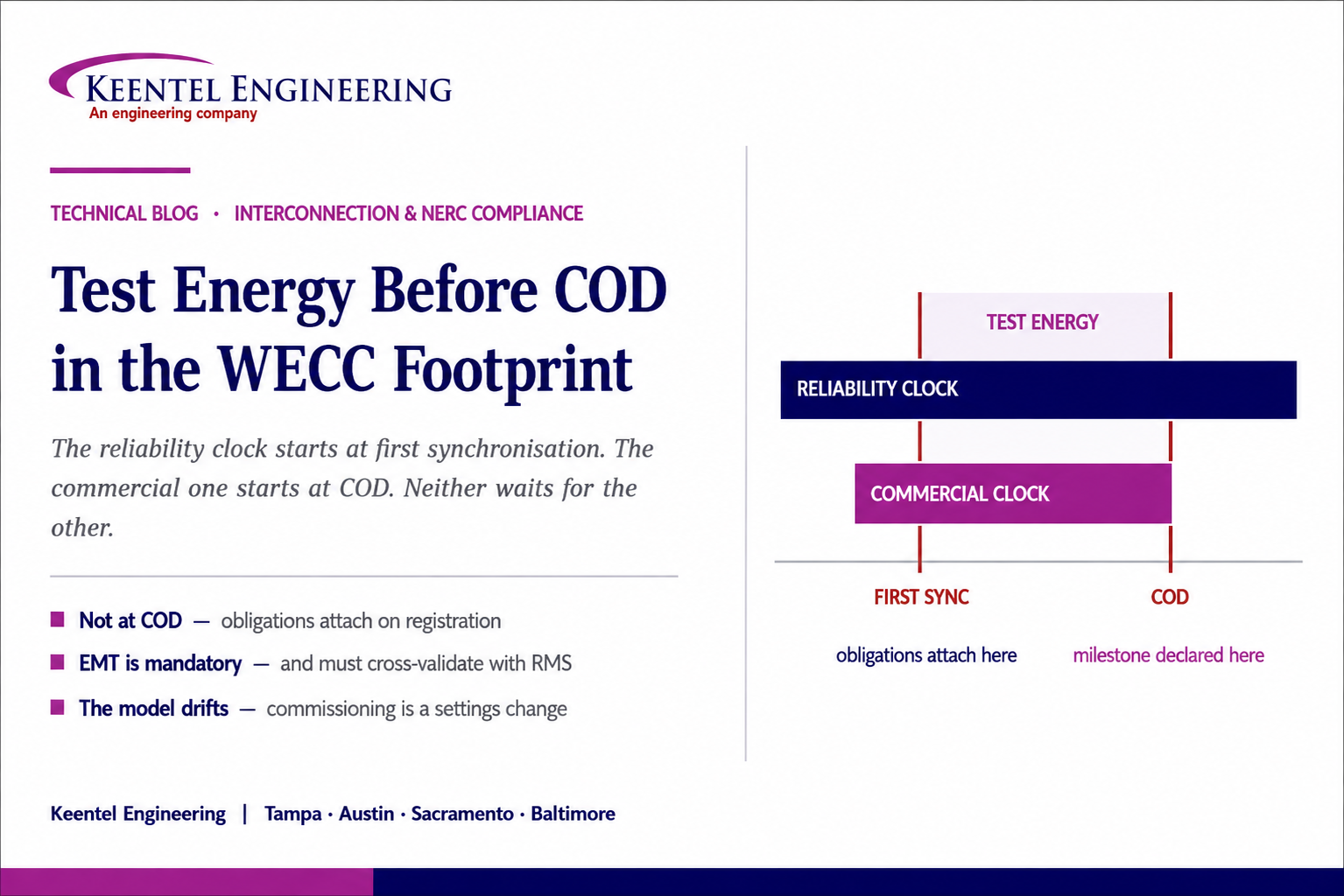
Learn how CAISO BESS projects manage test energy before COD, including WECC modeling, EMT studies, telemetry, ride-through, registration and compliance.
By SANDIP R PATEL
•
August 28, 2026
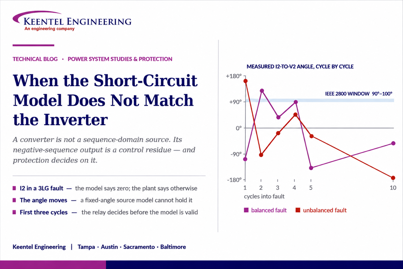
Learn why short-circuit models can misrepresent inverter fault behavior, negative-sequence current, protection settings, and when EMT studies are needed.
By SANDIP R PATEL
•
August 28, 2026
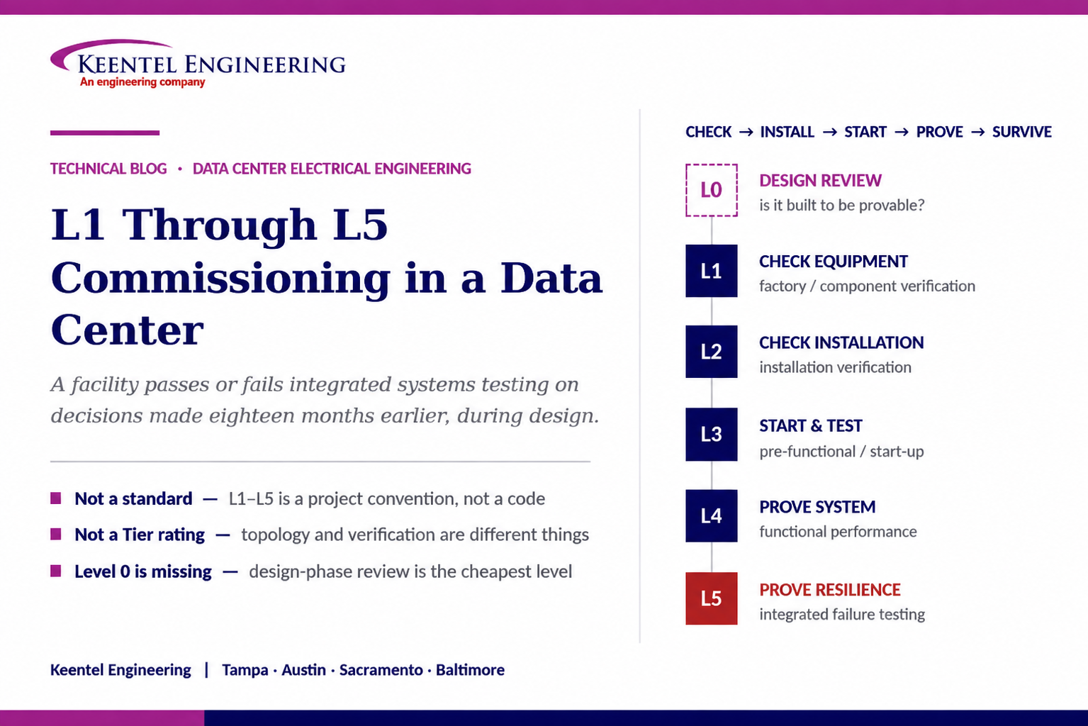
Understand L1-L5 data center commissioning levels, including factory testing, functional testing, integrated systems testing, and design requirements





