
A Coordinated Electric System Interconnection Review—the utility’s deep-dive on technical and cost impacts of your project.
Challenge: Frequent false tripping using conventional electromechanical relays
Solution: SEL-487E integration with multi-terminal differential protection and dynamic inrush restraint
Result: 90% reduction in false trips, saving over $250,000 in downtime
ERCOT enforces all of the above through simulation, which means your model is your compliance case. The bar is now high:
- Whole-facility scope. The model must represent everything the IT load, the UPS and power conversion, the cooling plant, the protection and control systems in formats compatible with ERCOT's study platforms (PSS/E, PSCAD, TSAT).
- Real control loops, not approximations. Generic textbook representations are unacceptable. The model must capture the actual inner control behavior of your power electronics.
- Hardware-validated converter models. For electronic loads, the PSCAD model must be benchmarked against actual hardware testing including voltage ride-through and subsynchronous response. A model assembled from standard PSCAD library blocks fails by definition, because a generic block has never been tested against your vendor's hardware. The good news: validation is a hardware-type test, so results for a given converter product are reusable across every facility that uses it.
- Format migration. Facilities that previously submitted the older composite load model (CMLD) format must transition to EPRI's PERC1 format.
- Three checkpoints. Models are reviewed before the stability study begins (no model, no study), before each quarterly stability assessment, and for electronic loads one final time before energization, when you must submit as-built models with a documented comparison against the previously studied data and a sworn attestation that the model matches actual field settings. ERCOT's review takes 10 business days, extendable by 20 put it on your critical path.
- A living obligation. Change your technology, controls, or relay settings in a way that affects ride-through including converting a crypto mining site to an AI data center — and you've triggered a new interconnection study, even if your megawatts don't change.
| Parameter | Detail |
|---|---|
| System | 230 kV / 138 kV transmission corridors, wind and wet-snow icing exposure |
| Data basis | 15 years of minute-resolution forced-outage records + regional weather observations |
| Core methods | Event grouping, MVA performance curves, time-to-95%-restore, area outage rate curves, fragility modeling, rerun-history benefits, exceedance and log-domain risk metrics |
| Headline result | ≈85% of maximum resilience benefit at 60% of original capital; worst-event restoration window cut from 11 days to 5 in rerun-history terms |
| Decision supported | Capital portfolio selection; resilience plan filing; post-investment verification framework |
| System / Topic | Governing Standard(s) | What It Controls |
|---|---|---|
| Overall plant electrical distribution | IEEE 141 (Red Book); IEEE 666 | Distribution architecture, voltage selection, design of generating station auxiliary service systems |
| Power system studies | IEEE 399 (Brown Book); IEEE 551 | Load flow, symmetrical/asymmetrical short circuit, motor starting methodologies down to the lowest LV panelboard |
| Protection & coordination | IEEE 242 (Buff Book); IEEE 3004.5; IEEE C37 series | Generator relaying (21, 59N, 87G), time-current coordination, selective clearing between LV and MV tiers |
| GSU / UAT / SST transformers | IEEE C57.12.00 and C57 family | Transformer ratings, impedance, testing, loading |
| HV switchyard breakers | IEEE C37.06 | AC high-voltage circuit breaker preferred ratings |
| MV switchgear (13.8 kV) | IEEE C37.20.2; IEEE C37.20.7 | Metal-clad construction, compartmentalization, vacuum breakers; arc-resistant design with plenum venting |
| MV cable | UL 1072; ICEA S-93-639 (NEMA WC 74) | Type MV-105 shielded cable, 133% insulation level for HRG systems |
| LV switchgear (480 V) | IEEE C37.13; UL 1558 | Metal-enclosed LV power circuit breaker switchgear to 635 V, draw-out ACBs with electronic trip units |
| Motor control centers | UL 845; NEMA ICS 18 | LV-MCC construction, MCCB/MCP protection for motors under ~200 HP |
| Motors | NEMA MG-1 | Motor performance, starting characteristics, service factors |
| DC & battery systems | IEEE 485; IEEE 946 | Lead-acid battery sizing (125/250 VDC), DC auxiliary system design |
| Grounding | IEEE 80; IEEE 142 (Green Book) | Ground grid step/touch potential limits; system grounding including high-resistance grounding |
| Lightning protection | IEEE 998 | Direct-stroke shielding of switchyard and outdoor generator structures |
| Arc flash & electrical safety | IEEE 1584; NFPA 70E | Incident energy calculation; worker safety boundaries and PPE |
| Fire protection | NFPA 850 | Fire protection and risk management for combustion turbine generating plants |
| Installation code | NEC (NFPA 70); NESC | Wiring methods inside the plant fence; overhead/outdoor clearances at the switchyard |
| Interconnection & compliance | FERC LGIP; NERC MOD-025/026/027, PRC-019/024/029, FAC-008 | Interconnection process, model validation, protection/ride-through coordination, facility ratings |
| IFC / Construction Deliverable | Purpose |
|---|---|
| Stamped IFC packages | Legal basis for construction; P.E. responsible charge |
| Final relay settings & TCCs | Protection as-installed matches the coordination study |
| Calculation archive | Owner records; NERC audit evidence trail |
| Commissioning procedures | Safe, sequenced energization; MOD field testing |
| Construction support | RFIs, field changes, FAT/SAT witness |
| As-builts & model handoff | Operating baseline; future study currency |
| Metric | Outcome |
|---|---|
| Defects found pre-occupancy | Three topology defects and one settings-mismatch family corrected before load migration; the shared-switchboard defect alone would have invalidated the concurrently-maintainable claim on day one |
| IST findings | Fourteen additional discrepancies surfaced under scenario testing (control logic, alarm mapping, one generator sequencing fault) — all closed before handover instead of during operations |
| Black-building test | Passed on second execution; the first attempt exposed the generator sequencing fault under true block load, exactly the failure the compressed plan would never have found |
| Handover quality | Operations team certified on the actual failure scenarios; corrected EOPs and settings documentation delivered as controlled documents |
| Business outcome | Occupancy proceeded three weeks behind the original date — against an independent estimate that the uncorrected sequencing fault carried a high probability of a full facility outage within the first year |
Part 2 — Frequently Asked Questions: Large Load Interconnection
An electric grid must remain in continuous balance — generation onto the grid must equal consumption from it at every instant. PJM achieves this balance, and prices it, through a layered market architecture. Each layer operates on a different time horizon, and each one touches project economics differently.
| Domain | Key Standards / Codes | What They Govern |
|---|---|---|
| Fire safety | NFPA 855; UL 9540 / UL 9540A | Installation requirements, separation, gas management; system safety listing and thermal-runaway fire testing |
| Grid interconnection | IEEE 1547 (distribution); IEEE 2800 (transmission IBRs) | Ride-through, reactive capability, power quality, and performance at the point of interconnection |
| Power quality | IEEE 519 | Harmonic distortion limits at the PCC |
| Protection & grounding | IEEE 80 / 81 / 142; C37 series | Grounding system design and testing; protective relaying |
| Reliability compliance | NERC standards (incl. PRC ride-through requirements) | Registered-entity obligations for grid-connected storage |
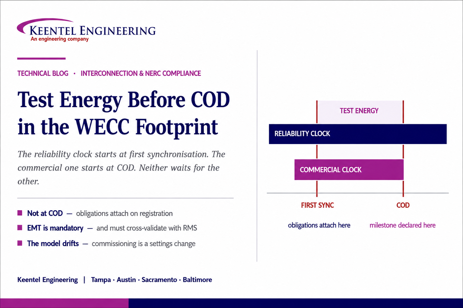
Test Energy Before COD in the WECC Footprint
Aug 28, 2026 | Blog
What a CAISO-Interconnected Battery Storage Project Has to Model, Test, and Prove Between First Synchronization and Commercial Operation — and Why the Reliability Clock Starts Before the Commercial One
1. Executive Summary
Every generating or storage project in the Western Interconnection delivers energy before it reaches its Commercial Operation Date. That is not an exception or a workaround; it is how a facility is commissioned. Inverters are energised, the plant controller is tuned, ride-through settings are loaded, reactive capability is proven at the point of interconnection, and metering and telemetry are validated against live production. All of it happens in the window between first synchronisation and COD, and all of it produces energy that has to be scheduled, settled, curtailed, and accounted for.
That window is governed by two frameworks that run on different clocks and answer to different parties. The commercial framework lives in the power purchase agreement and the interconnection agreement: what test energy is worth, who can curtail it and on what notice, which milestones must be declared, and what happens to the schedule if a milestone slips. The reliability framework lives in the NERC Reliability Standards and in the regional modeling and testing requirements administered through the Transmission Planner, the Area Coordinator, and WECC. It does not care what the offtake agreement says.
The most consequential misconception in this space is that reliability compliance begins at COD. It does not. Obligations attach on registration, and a facility becomes an operating element of the system the moment it first synchronises. A project that plans its compliance program around the commercial milestone spends its entire commissioning window operating with obligations already live and no evidence being generated to demonstrate them.
The second most consequential misconception is that the model submitted during the interconnection study is the model that governs. It is not. What governs is a verified as-built representation of the equipment actually installed, with the control parameters actually loaded — and those parameters are adjusted by the vendor during commissioning, in the same weeks the developer is certifying that the as-built matches the study. That drift, between the studied baseline and the tuned plant, is where most late-stage interconnection problems originate.
This paper works through the pre-COD window for a battery storage project interconnecting to CAISO within the WECC footprint: the implementation path and its gating milestones, the metering and telemetry requirements peculiar to storage, the modeling chain and the model stack, why electromagnetic transient models are now a separate mandatory obligation rather than a study refinement, how the registration and ride-through clocks interact with a COD date, and what a defensible pre-COD test program contains. It closes with a backward timeline from COD, a failure taxonomy, and a twenty-question FAQ.
Two sentences worth internalising
Test energy is delivered by a facility that is already a registered entity with live obligations, into a market that will curtail it without compensation, under a model that has to match what was actually built.
The commercial milestone and the reliability milestone are not the same date, and neither one waits for the other.
2. Two Clocks, One Project
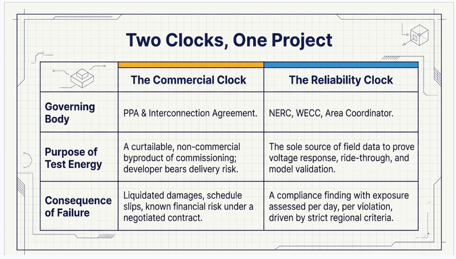
It helps to separate the obligations by who imposes them, because the consequences of missing them are entirely different in kind.
2.1 The Commercial Clock
- Power purchase agreement terms governing test energy: whether it is compensated at all, at what price, and under what conditions. In the Western markets it is common for pre-COD deliveries to be curtailable by the buyer or the balancing authority without compensation, and for the developer to bear the delivery risk entirely. This is a negotiated term, not a regional rule — read the agreement rather than assuming the market norm.
- Interconnection agreement milestones: the right to test and to deliver test energy, notice obligations to the transmission provider, and the declaration mechanics for commercial operation.
- Guaranteed commercial operation dates and the liquidated damages, security draws, or termination rights that attach to slipping them.
- Market and registry mechanics: scheduling coordinator arrangements, resource identification, and registration in generation attribute tracking systems where environmental attributes from the test period are to be claimed. Attribute registration generally has to be in place before the energy is produced, not reconciled afterwards.
2.2 The Reliability Clock
- Registration as a Generator Owner and Generator Operator, which attaches by criteria rather than by contract, and which now reaches well below the traditional Bulk Electric System thresholds for inverter-based resources.
- Modeling data submittal to the Transmission Planner and Planning Coordinator, on their published schedules and in their specified formats.
- Dynamic model verification and validation, now including electromagnetic transient models for inverter-based resources.
- Ride-through performance requirements and the disturbance monitoring that demonstrates them.
- Facility ratings, protection system maintenance, relay loadability, and voltage control coordination obligations that begin when the facility begins operating, not when it begins selling.
Why the distinction is not academic
A commercial milestone that slips costs money under a contract that both parties negotiated and both parties understand.
A reliability obligation that was live during commissioning and generated no evidence is a compliance finding, and the exposure is assessed per day per violation. The two risks are not comparable and should not sit in the same column of a project risk register.
3. What Pre-COD Test Energy Actually Is
Test energy is the electrical output of a facility that is being commissioned rather than operated. Its purpose is to exercise equipment and prove performance, and every megawatt-hour of it is a by-product of a test rather than a product being sold. Three characteristics follow from that and shape everything downstream.
First, it is uncontrolled in the market sense. The plant is being started, stopped, ramped, stepped, and deliberately disturbed on the test engineer’s schedule, not the dispatcher’s. That is why it is treated as curtailable and why the balancing authority needs visibility into it before the first synchronisation rather than after.
Second, it is the only source of the field data that the compliance program ultimately rests on. Reactive capability, voltage control loop response, ride-through behaviour, and model validation all require the plant to be operating. There is no way to generate the evidence without generating the energy, which is precisely why the reliability obligations are live during the window that developers think of as pre-operational.
Third, for a storage resource it is bidirectional. Charging energy is load. It is metered, settled, and accounted for differently from discharge, and the metering configuration that makes that distinction correctly has to be in place and validated before the resource can be certified. A storage project that treats test energy as a generation-only concept discovers the problem at the metering validation step.
4. The CAISO New Resource Implementation Path
For a project interconnecting to CAISO, the pre-COD window is administered through the New Resource Implementation process, which is organised into a sequence of grouped deliverables commonly referred to as buckets and administered through the ISO’s resource interconnection management system. The process is tied to the network model build cycle, which means the milestone dates are not purely a function of construction progress — they are a function of which network model build the resource lands in.
4.1 The Gating Structure
Two gates matter more than the rest, and both are hard.
The first gate is the request to synchronise. The earlier deliverable groups must be complete and accepted before the interconnection customer may request permission to synchronise to the grid, and the request itself carries a processing period on the order of two working weeks. Metering and telemetry point-to-point testing must be successfully completed before that gate opens. This is the point at which many projects discover that a metering or telemetry deficiency they had classified as a punch item is in fact a schedule-critical blocker.
The second gate is the request for commercial operation. All deliverable groups plus the metering site verification documentation must be received and accepted before the interconnection customer may request the commercial operation date, and that request carries its own processing period. The customer then files the commercial operation declaration with an effective date. Nothing about this sequence is automatic and none of it can be compressed by declaring readiness.
4.2 Trial Operations and Live Data Validation
Between the two gates sits the trial operations period, which is the real subject of this paper. Preliminary meter data validation happens here. Final validation of metering and telemetry is performed after synchronisation using actual generation data — which is to say, using test energy. The certificate confirming compliance is issued following that validation against live production.
The practical consequence is that the pre-COD window is not slack in the schedule. It is a required data-generation period with a minimum duration set by how long it takes to produce clean, validated operating data across the required conditions. Projects that plan a two-week commissioning window and a same-month COD are planning a schedule that the process cannot support.
The scheduling coordinator point
The scheduling coordinator arrangement must be in place and stable through the window. Changing scheduling coordinators mid-process, particularly before the compliance certificate is issued, creates a settlement gap that nobody recovers.
The legal entity named in the interconnection agreement must match the entity requesting market participation exactly. Entity mismatches from mid-development transfers and financing structures are a routine cause of avoidable delay.
5. Metering and Telemetry for a Storage Resource
Storage metering is where the pre-COD window most often breaks, because the requirements are structurally different from those for a generator and are frequently designed as if they were not.
5.1 Separating Wholesale Charging From Retail Station Load
A battery facility consumes energy for two entirely different reasons. It charges the battery, which is a wholesale market transaction. It also runs auxiliary load — thermal management, controls, lighting, fire systems — which is retail station service. Those two consumptions must not be commingled in the revenue metering, and the metering configuration has to be able to distinguish them under all operating states, including the state where the battery is neither charging nor discharging and the auxiliary load is still running.
This is a design problem, not a metering technician problem. It has to be settled in the single line and the metering design during engineering. Discovering during meter validation that the current transformer placement cannot separate the two flows is a rework item on energised equipment inside the commissioning window.
5.2 Telemetry Content and Cadence
Real-time telemetry to the balancing authority for a storage resource carries more than the real and reactive power points a generator provides. State of charge and the instantaneous charge and discharge limits are operationally necessary — without them the operator cannot know what the resource can actually do in the next interval. Point lists, scan rates, and the gateway configuration must be established, mapped, and point-to-point tested before the synchronisation gate.
The telemetry design also has to survive the commissioning period itself, during which the plant controller is being tuned and the values being reported may be transiently wrong. Telemetry that reports a nonsensical state of charge or an out-of-range limit during tuning generates operator queries and, in the worst case, a hold
6. The WECC Modeling Chain
The path a model takes from the field to the interconnection-wide base cases is a chain of custody with several parties in it, and understanding the chain explains why late as-built changes are so expensive.
The developer submits the steady-state and dynamic data package to the Transmission Planner, which validates it against regional criteria. The Transmission Planner passes it to the Area Coordinator, which integrates the data into the regional power flow base cases. The compiled cases go to WECC staff, which verifies that the models initialise cleanly in the interconnection-wide dynamics environment without producing numerical errors or artificial oscillations. Only after that does the representation of the facility become part of the case that everyone else studies against.
Data is prepared for the platform WECC uses to assemble the base cases and is converted for the other major planning platform, which is why model submittals must be expressible in the accepted library rather than as a proprietary artefact. A model that cannot be represented in the accepted library cannot enter the chain at all.
6.1 The Modeling Rules That Trip Projects
- Generator step-up and main station transformers must be modelled explicitly. Impedance folded into the generator representation is a common submittal rejection and produces incorrect voltage and reactive results at the point of interconnection.
- The full reactive footprint must initialise cleanly — capacitor banks, static compensators, reactors, and any dynamic reactive equipment. A case that will not solve with the plant’s reactive equipment in service is a case that gets returned.
- The collector system must be represented as an equivalent that reproduces the real losses and impedance seen at the point of interconnection, not as a nominal placeholder.
- Any equipment deviation from the configuration studied in the cluster process must be documented and carried forward, because the base case has to describe the facility that exists.
7. The Model Stack for a BESS
For positive-sequence work, inverter-based resources are represented by an approved library of generic models rather than by vendor-proprietary code. The stack for a battery facility is three layers, and each layer has current and superseded variants that matter.
| Layer | Function | Current practice notes |
|---|---|---|
| Generator / converter | Represents the inverter interface: real and reactive current injection and the converter current limits | Two approved variants are in use; the newer one improves representation of converter behaviour and is the appropriate selection for new facilities unless the Transmission Planner specifies otherwise |
| Electrical control | Local active and reactive control at the unit level: volt/var behaviour, power factor and reactive limits, current priority | The storage-specific variant carries state-of-charge logic and charge/discharge constraints and is the correct choice for a BESS. A newer general variant also exists; it is not a storage-specific model and should not be selected merely because it is newer |
| Plant controller | Centralised control at the point of interconnection: voltage, reactive, power factor, and active power regulation | The original variant is being phased out in favour of the current advanced controller model. New submittals should use the current model; projects carrying an older selection from an earlier study phase should confirm what the Transmission Planner will accept |
Two further points are worth stating because they are routinely missed.
First, the first-generation wind models were retired years ago and the current representation of a Type 3 or Type 4 wind facility is a composite of the same converter and electrical control layers plus separate drivetrain, aerodynamic, pitch, and torque control modules. Any submittal still carrying first-generation wind model names is carrying a rejection.
Second,
grid-forming inverter models now exist in the approved library and have been approved for interconnection-wide studies. If a project is procuring grid-forming capability — which is increasingly relevant at weak points of interconnection and for facilities with islanding requirements — the modeling approach should be settled at procurement, not discovered during the as-built submittal.
8. EMT Is a Separate and Now Mandatory Obligation
The single largest change in this area, and the one most likely to be missing from a project’s compliance plan, is that electromagnetic transient models are no longer an optional refinement requested by some Transmission Planners. The consolidated dynamic model verification and validation standard became effective in 2026, superseding and retiring the two predecessor standards that previously governed voltage regulator and turbine-governor model verification separately.
The obligation now has three parts that did not previously exist together.
- A verified electromagnetic transient model of the facility must be provided to the Transmission Planner for inverter-based resources, covering the inverters, the collector system, auxiliary control devices, the plant controller, the step-up and main transformers, and the protective functions and limiters on both the AC and DC sides.
- The electromagnetic transient model and the positive-sequence model must be cross-validated against each other under large-signal disturbances, with discrepancies resolved and documented. Submitting two models that were each developed independently and never compared does not satisfy this.
- Models must be updated and resubmitted within a defined period after any change at the facility that alters dynamic response — hardware, software, firmware, control mode, or settings.
Why this lands squarely in the pre-COD window
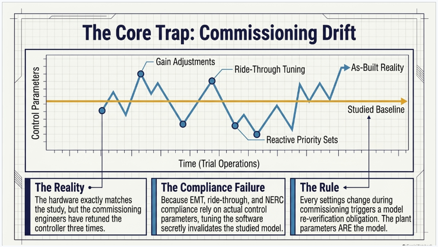
The change triggers include settings and control-mode changes. Commissioning is a settings-change exercise by definition: the plant controller is tuned, ride-through parameters are loaded, reactive priority is configured, and ramp limits are set.
A project that freezes its model before commissioning and does not re-verify after tuning has, by the plain terms of the obligation, a model that no longer represents the in-service equipment — and it acquired that condition during the exact period when it was certifying that the as-built matched the study.
There is a narrow exception for legacy facilities where the original equipment manufacturer no longer supports an electromagnetic transient model, and for legacy facilities the Transmission Planner has not identified as applicable. Neither exception helps a new project. For anything being commissioned now, the model deliverable and the right to use it should be a procurement requirement written into the inverter and plant controller purchase, because obtaining a validated model from a vendor after the order is placed is a negotiation rather than an entitlement.
9. The Registration Clock
Registration is the step that converts a project into a compliance entity, and its threshold has moved. Inverter-based resources that individually or collectively reach an aggregate nameplate capacity of twenty megavolt-amperes or more, connected through a system delivering that capacity to a common point of connection at sixty kilovolts or above, now fall into a registration category that did not exist a few years ago and are required to register as Generator Owner and Generator Operator.
Two features of that criterion catch projects. It is an aggregate test, so several individually sub-threshold facilities sharing a common point of connection are assessed together. And it reaches well below the traditional Bulk Electric System threshold, which means a substantial population of projects that were designed, financed, and staffed on the assumption that NERC compliance did not apply to them are now inside the framework.
For a project in commissioning, the practical question is sequencing. Registration is not triggered by commercial operation. A facility that will meet the criterion should have its registration status resolved, its compliance program stood up, and its evidence-retention practice running before test energy begins — because the standards that apply on registration include obligations that can only be demonstrated with records made during the commissioning window.
10. Ride-Through and Disturbance Monitoring
Three related standards now govern inverter-based resource performance during system disturbances, and their implementation dates interact with a COD date in a way that materially affects projects reaching commercial operation now.
10.1 The Three-Part Structure
- Disturbance monitoring and reporting for inverter-based resources, which took effect in 2025, requires the recording capability — sequence of events, fault recording, and dynamic disturbance recording — that everything else depends on.
- Ride-through performance, effective in the fourth quarter of 2026, requires the resource to remain connected and continue delivering current through defined voltage and frequency disturbance envelopes, with momentary cessation prohibited within the no-trip region.
- Post-disturbance analysis and mitigation, effective on the same date, requires unexpected changes in real power output following disturbances to be identified, analysed, and corrected.
The dependency runs one way. Ride-through performance cannot be demonstrated, and post-disturbance analysis cannot be performed credibly, without the records the monitoring standard mandates. The three should be designed as a single data architecture rather than as three separate compliance projects.
10.2 The COD Interaction That Matters Right Now
The implementation plan for the ride-through standard separates capability-based design obligations from performance-based operational obligations. For facilities on the Bulk Electric System, existing resources were given a phase-in to the effective date. Resources reaching commercial operation after the effective date are not: they must comply with the design requirements at commercial operation, with no transition period. Facilities below the Bulk Electric System threshold have a later date, and a limited exemption pathway exists for existing resources with verified hardware limitations that cannot be resolved through software or settings — an exemption that does not assist a project being built now.
For a project whose COD falls after the effective date, this means the ride-through settings loaded during commissioning are not a best-effort configuration to be optimised later. They are a compliance deliverable that has to be right at COD, verified, and evidenced. The operational demonstration follows once the monitoring capability is established, but the design obligation is immediate.
Practical sequencing consequence
Ride-through parameter verification cannot be the last item in the commissioning punch list. If it fails, the remedy may be a firmware change, a settings change requiring vendor involvement, or in the worst case a hardware limitation — and each of those triggers a model re-verification obligation on top of the schedule impact.
It should be tested early in the pre-COD window, when there is still time to do something about the answer.
11. Three Thresholds That Are Not the Same
Three numeric thresholds circulate in these conversations and are regularly conflated. They govern different obligations and a project can fall on different sides of each.
| Threshold | What it governs | Consequence of meeting it |
|---|---|---|
| Regional modeling data thresholds | Whether individual steady-state and dynamic models must be submitted for the unit or facility rather than an aggregate representation | Data submittal obligations to the Transmission Planner and inclusion in the interconnection-wide base cases |
| NERC registration criteria for inverter-based resources | Whether the owner and operator must register as Generator Owner and Generator Operator | The full applicable body of Reliability Standards, with enforcement exposure assessed per day per violation |
| Market and deliverability criteria | Resource adequacy status, deliverability, and market participation obligations | Commercial value and market obligations — and a separate set of milestone dates that do not align with the reliability ones |
The failure mode is assuming that clearing one threshold determines the others. A facility can be below the traditional Bulk Electric System definition, above the inverter-based resource registration criterion, and subject to individual modeling submittal, all at once. Screening against all three at the start of the project, and re-screening whenever the facility rating or configuration changes, is a half-day exercise that prevents a category of very expensive surprises.
12. As-Built Verification and Material Modification
The as-built obligation exists because the base cases and the studies that depend on them must describe the facility that was actually built. Two distinct requirements are frequently conflated and should not be.
12.1 Two Different Sixty-Day Windows
One requirement runs before commercial operation: as-built documentation demonstrating that the parameterised equipment on site matches the baseline used in the study process, submitted in advance of the commercial operation milestone. The other runs after: a period of continuous, high-quality operating and telemetry data used to complete certification and to support forecasting and resource classification. They have different owners, different content, and different consequences, and a compliance plan that treats them as one item will miss one of them.
12.2 The Material Modification Question
If the as-built configuration differs from what was studied — a different inverter manufacturer, a different unit count, a materially different reactive capability, a changed collector arrangement — the transmission provider has to determine whether the change constitutes a material modification. A determination that it does can return the project to the study process, with the queue and schedule consequences that implies. A determination that it does not still requires as-built validation data demonstrating that the delivered configuration behaves acceptably.
The engineering discipline that avoids this is unglamorous: maintain a controlled record of the studied baseline, log every deviation as it occurs with its electrical significance assessed at the time, and raise material questions with the transmission provider early rather than presenting an accumulated set of changes at the as-built submittal. A single deviation raised in month four is a conversation. Eleven deviations presented in month sixteen is a restudy.
12.3 Commissioning Drift
The deviations that matter most are not hardware. Hardware changes are visible, procured, and documented. Control parameters are not: the plant controller gains, the reactive priority setting, the ramp limits, the ride-through thresholds, and the protection setpoints are adjusted by commissioning engineers and vendor technicians, often iteratively, often without a change record that anyone outside the commissioning team sees. Those parameters are the model. A plant whose hardware exactly matches the study and whose controller has been retuned three times has an as-built model that does not match the study.
13. The Pre-COD Test Program
A defensible pre-COD test program produces three things simultaneously: permission to proceed, evidence for the compliance file, and validated model parameters. Designing it to produce only the first is the common error.
- Pre-synchronisation verification: protection settings against the current coordination study revision, metering and telemetry point-to-point testing, grounding and interconnection facility verification, and confirmation that the settings loaded in the inverters and the plant controller match the parameters in the submitted model.
- First synchronisation and initial energisation, with the balancing authority notified and the testing plan agreed. Record the plant’s behaviour from the first energisation — the disturbance recording capability should be commissioned before, not after, the first switching operations.
- Reactive capability verification at the point of interconnection across the full range, lagging and leading, at multiple real power levels, and for a storage resource in both charging and discharging states. Reactive capability is not symmetric across operating states and testing only one is testing half the plant.
- Voltage control loop verification: step-response testing of the plant controller and unit-level controls, with oscillography captured at sufficient resolution to support model calibration. This is the test whose data validates the model, so it must be planned as a data-collection exercise with predefined step magnitudes and recording configuration, not performed as a tuning session that happens to be recorded.
- Active power control and ramp behaviour verification, including the response to dispatch instructions and the ramp rate limits actually configured.
- Ride-through parameter verification: confirmation that the voltage and frequency ride-through settings physically loaded in the equipment implement the required envelopes, that momentary cessation is not configured within the no-trip region, and that protection settings do not defeat the ride-through requirement. Perform this early.
- Storage-specific tests: state-of-charge reporting accuracy, charge and discharge limit reporting, transition behaviour between charging and discharging, and auxiliary load separation verified through the metering under all operating states including idle.
- Model calibration and re-verification: compare recorded field response against the simulated response, adjust model parameters to match measured behaviour, and re-verify the positive-sequence and electromagnetic transient models against each other. Then submit the corrected models.
- Compile and retain the evidence package: test procedures, as-run records, recorded data, settings files as loaded, model files as submitted, and the correspondence documenting acceptance. This package is the compliance file and it is also the only defence if a disturbance later raises questions about the facility’s performance.
14. Counting Backward From COD
The following is an indicative planning sequence. Actual durations depend on the network model build cycle, the Transmission Planner’s data schedule, equipment lead times, and the project’s registration status — but the ordering is stable and the dependencies are real.ti
| Relative timing | Reliability and modeling track | Commercial and market track |
|---|---|---|
| Design and procurement | Model deliverables written into equipment specifications; registration screening against all applicable thresholds; disturbance monitoring architecture designed | Interconnection agreement executed; offtake terms for test energy settled; scheduling coordinator arrangement established |
| Roughly 6–12 months before COD | Controlled baseline of studied configuration established; deviation log opened; monitoring and recording equipment procured | Implementation process entered; early data and contract deliverables submitted; network model build slot confirmed |
| Roughly 3–6 months before COD | Model package prepared for as-built submittal; protection settings verified against current coordination study; compliance program and evidence retention operating | Metering and telemetry design finalised and equipment installed; entity and resource identification confirmed |
| Before first synchronisation | Settings verified against submitted model; disturbance recording commissioned; testing plan agreed with the balancing authority | Earlier deliverable groups accepted; metering and telemetry point-to-point testing complete; synchronisation request submitted with its processing period |
| Trial operations window | Reactive capability, voltage control, active power, ride-through, and storage-specific testing executed with data captured; model calibrated and re-verified | Test energy delivered and settled under the applicable terms; live metering and telemetry validation performed against actual production |
| Approaching COD | As-built documentation submitted; material modification questions resolved; corrected models submitted; ride-through design compliance evidenced | Remaining deliverable groups and metering verification accepted; commercial operation request submitted with its processing period; declaration filed |
| After COD | Continuous high-quality operating data period completed; ongoing model maintenance obligations begin; operational ride-through demonstration proceeds as monitoring data accumulates | Resource adequacy, deliverability, and attribute tracking obligations proceed on their own schedules |
15. What Actually Goes Wrong
| Failure | Where it originates | How it surfaces | What prevents it |
|---|---|---|---|
| Commissioning settings drift from the submitted model | Vendor tuning during commissioning with no change control | As-built submittal cannot be certified, or a later model verification finds the mismatch | Controlled settings register; model re-verification after tuning as a planned step |
| EMT model unavailable or not licensed for the required studies | Procurement specification silent on model deliverables | Study cannot be run; Transmission Planner will not accept the submittal | Model deliverable, format, and usage rights written into the equipment purchase |
| Metering cannot separate wholesale charging from station load | Metering and single-line design treated the facility as a generator | Meter validation fails at the synchronisation or certification gate | Storage-specific metering design reviewed during engineering |
| Ride-through settings fail verification late | Testing scheduled at the end of the commissioning sequence | Firmware or hardware remedy required with no schedule float | Ride-through verification performed early in the window |
| Registration status unresolved when test energy begins | Assumption that obligations attach at COD | Obligations were live with no evidence generated; exposure accrues per day | Threshold screening at project start; compliance program running before first synchronisation |
| As-built differs materially from the studied configuration | Deviations accumulated without contemporaneous assessment | Material modification determination; possible return to study | Deviation log with electrical significance assessed as each change occurs |
| Obsolete or wrong model variants submitted | Model selection inherited from an earlier study phase | Submittal rejected; resubmittal cycle consumes schedule | Model library currency confirmed at the time of the as-built submittal, not at the time of the study |
| Base case will not initialise | Reactive equipment or collector equivalent incorrectly represented | Returned by the Area Coordinator or WECC staff late in the chain | Initialisation tested locally before submittal rather than relying on downstream review |
| Schedule assumes the pre-COD window is float | Commercial schedule built without the data-generation period | COD slips; guaranteed date and damages exposure | Trial operations treated as a required duration with its own deliverables |
16. Keentel Interconnection and Compliance Services
Keentel Engineering supports developers, owners, and independent engineers through exactly this window — from the study-phase model that establishes the baseline to the as-built package and the evidence file that closes it out.
16.1 Interconnection Engineering and Studies
- Point-of-interconnection engineering substation and collector system design, and interconnection facility design for generation and storage projects.
- Load flow, short-circuit, protective coordination and selectivity, and arc-flash studies, with inverter-based resources represented as current-limited sources rather than as equivalent machines.
- Harmonic, flicker, grid strength, and transient stability analysis, and electromagnetic transient modelling for control interaction, weak-grid stability, ride-through verification, and switching and overvoltage studies.
- Effective grounding and ground fault overvoltage assessment, insulation coordination, and ground grid analysis.
16.2 Modeling and Model Validation
- Positive-sequence and electromagnetic transient model development, cross-validation, and submittal packages prepared to the Transmission Planner’s specified format and level of detail.
- Model verification and validation against staged test data and disturbance records, including step-response test design, data capture specification, and parameter calibration.
- Baseline control and model management: establishing the studied configuration of record, tracking commissioning-phase deviations, and re-verifying after settings, firmware, or control-mode changes.
- As-built data package preparation and support through the Transmission Planner, Area Coordinator, and interconnection-wide review chain.
16.3 NERC Compliance Support
- Registration threshold screening and applicability assessment across modeling, registration, and market criteria.
- Ride-through design evaluation, disturbance monitoring architecture, and post-disturbance analysis programs designed as a single data lifecycle.
- Facility ratings, protection system maintenance programs, relay loadability, and voltage control coordination.
- Evidence package structure and retention practice built during commissioning rather than reconstructed for an audit.
16.4 Owner’s Engineer and Commissioning Support
- Pre-COD test program development, test procedure authorship traceable to the design basis and the compliance obligations, and witness support during execution.
- Design review of EPC and vendor submittals, QA/QC of third-party study and model packages, and equipment specification including model and test deliverables.
Keentel Engineering holds a Florida Certificate of Authorization and maintains offices in Tampa, Austin, Sacramento, and Baltimore, supporting projects across the interconnections.
17. Frequently Asked Questions
It is unavoidable. Commissioning a generating or storage facility requires operating it, and operating it produces energy that has to be scheduled, settled, and accounted for. The question is never whether test energy will be delivered but under what commercial terms, with what visibility to the balancing authority, and against which compliance obligations.
That is a contract term, not a regional rule. It is common in Western agreements for pre-COD deliveries to be curtailable by the buyer or the balancing authority without compensation, with the developer bearing the delivery risk. But it is negotiated, it varies by counterparty, and the only reliable answer for a specific project is in that project’s agreement. Be sceptical of any source that states it as a uniform market-wide rule.
No, and this is the most consequential misconception in the topic. Obligations attach on registration, and registration is driven by the applicable criteria, not by a commercial milestone. A facility that first synchronises is an operating element of the system from that moment. Planning a compliance program around COD means spending the entire commissioning window with obligations live and no evidence being generated.
Inverter-based resources that individually or collectively reach an aggregate nameplate capacity of twenty megavolt-amperes or more, connected to a common point of connection at sixty kilovolts or above, fall into the newer registration category and must register as Generator Owner and Generator Operator. It is an aggregate test, so multiple sub-threshold facilities sharing a point of connection are assessed together, and it reaches well below the traditional Bulk Electric System threshold.
Two hard gates. The earlier deliverable groups must be complete and accepted, and metering and telemetry point-to-point testing successfully completed, before permission to synchronise can be requested. All deliverable groups plus the metering site verification must be accepted before the commercial operation request can be made. Each request carries its own processing period, and neither can be compressed by asserting readiness.
Because final metering and telemetry validation is performed after synchronisation using actual production data, and the compliance certificate follows that validation. The window has a minimum duration set by how long it takes to generate clean, validated data across the required conditions. A commissioning plan that allows two weeks and a same-month COD is not compatible with the process.
A battery consumes energy for two different reasons — wholesale charging and retail station service — and the metering must distinguish them under every operating state, including idle, when the battery is doing nothing and the auxiliary load is still running. This has to be resolved in the single line and the metering design during engineering. Discovering it at meter validation means rework on energised equipment inside the commissioning window.
More than a generator. In addition to real and reactive power, the operator needs state of charge and the instantaneous charge and discharge limits, because without them the resource’s capability in the next interval is unknown. Points, scan rate, and gateway configuration must be established and point-to-point tested before the synchronisation gate.
A three-layer stack from the approved generic library: a converter model representing the inverter interface and its current limits, an electrical control model — for storage, the variant carrying state-of-charge logic and charge and discharge constraints — and a plant controller model regulating at the point of interconnection. Proprietary or black-box representations are not accepted for this purpose.
No, and stating it that way causes real problems. Positive-sequence submittals for the interconnection-wide base cases must use the approved generic library. Electromagnetic transient studies require vendor-supplied detailed models, which are precisely proprietary. Two obligations, two model types, two submittal paths. Conflating them leads projects to omit the EMT deliverable entirely.
Required. The consolidated model verification and validation standard that took effect in 2026 requires a verified electromagnetic transient model for inverter-based resources, covering the inverters, collector system, auxiliary controls, plant controller, transformers, and the protective functions and limiters on both AC and DC sides. It also requires the EMT and positive-sequence models to be cross-validated against each other under large-signal disturbances, with discrepancies resolved and documented.
A change at the facility that alters dynamic response: hardware, software, firmware, control mode, or settings. Updated models must be provided within the specified period after the change. Because commissioning is by definition a settings-change exercise, a model frozen before commissioning and never re-verified afterwards does not represent the in-service equipment.
The two predecessor standards that separately governed voltage regulator and turbine-governor model verification were retired when the consolidated standard took effect. Compliance plans and vendor scopes still referencing the old pair by number are working from a superseded framework, which is worth checking before an audit finds it.
Directly. The implementation plan separates design obligations from operational demonstration. Existing Bulk Electric System resources received a phase-in to the effective date; resources reaching commercial operation after that date must meet the design requirements at commercial operation with no transition. Facilities below the Bulk Electric System threshold have a later date. The practical effect is that ride-through settings are a compliance deliverable at COD, not a configuration to optimise afterwards.
Because the other two standards depend on its output. Ride-through performance is demonstrated with recorded disturbance data, and post-disturbance analysis requires the same records. The recording capability took effect earlier than the performance standards precisely so the evidence would exist when needed. Design the three as one data architecture, not as three projects.
They are unrelated. One runs before commercial operation: as-built documentation demonstrating that the equipment and its parameters match the studied baseline. The other runs after: a period of continuous high-quality operating and telemetry data supporting final certification and resource classification. Different content, different owners, different consequences. Sources that merge them are describing something that does not exist.
The transmission provider makes that determination, but the changes that raise the question are the ones that alter electrical behaviour at the point of interconnection: a different inverter manufacturer, a changed unit count, a materially different reactive capability, or a changed collector arrangement. A non-material determination still requires as-built validation data. A material determination can return the project to the study process.
Control parameter drift, not hardware. Hardware changes are procured, visible, and documented. Plant controller gains, reactive priority, ramp limits, ride-through thresholds, and protection setpoints are adjusted iteratively during commissioning, often without a change record visible outside the commissioning team — and those parameters are the model. Maintain a controlled settings register and treat model re-verification after tuning as a planned step.
Model deliverables and rights, explicitly: validated positive-sequence and electromagnetic transient models in the formats the Transmission Planner requires, with the right to use them for the required studies and to provide them to the Transmission Planner; factory test evidence supporting the model; and vendor support obligations for re-verification after firmware or settings changes. Obtaining these after the order is placed is a negotiation, not an entitlement.
Establish the studied configuration as a controlled baseline at the end of the study phase, and log every deviation from it — hardware and settings — with its electrical significance assessed at the time it occurs. Almost every expensive outcome in this window traces to deviations that were individually trivial, individually undocumented, and collectively material by the time anyone looked.
Notice and Disclaimer
This document is original technical content prepared by Keentel Engineering LLC for general professional information. It is not legal advice, regulatory advice, or project-specific engineering advice, and it does not constitute a compliance determination for any facility. Registration obligations, applicable Reliability Standards, implementation dates, regional modeling requirements, market processes, and interconnection procedures vary by facility, jurisdiction, registration status, and market region, and change over time.
Commercial terms concerning test energy — including compensation, curtailment rights, milestone declarations, and attribute tracking — are contractual and vary between counterparties. Descriptions of common practice in this document are general observations and are not a substitute for reading the applicable power purchase agreement, interconnection agreement, and tariff provisions.
Standards, implementation plans, model libraries, and market processes referenced by subject in this document are current to the date of publication to the best of our knowledge and are subject to revision. The governing versions are those published by the applicable standards body, regional entity, system operator, or authority, and should be verified directly for any project decision.
Keentel Engineering LLC is an independent engineering consultancy. Reference to any standard, market process, regional entity, system operator, industry organisation, or equipment category in this document does not imply affiliation with, endorsement by, or sponsorship from any such organisation or manufacturer.

About the Author:
Sandip "Sonny" R. Patel, P.E.
IEEE Senior Member · Founder & CEO, Keentel Engineering
In 1995, Sonny Patel earned his Electrical Engineering degree from the University of Illinois. But degrees don't build legacies — action does.
For three decades, he has worked the power industry from every side of the table: 16 years as a utility engineer at Exelon/Commonwealth Edison; generation leadership across hydroelectric, industrial steam turbine, and a 9 GW renewable fleet; NERC Regional Entity Senior Compliance Engineer and Audit Team Lead, auditing some of the nation's largest utilities; and testing and commissioning lead on equipment up to 765 kV — the very top of the North American grid.Utility. Generator. Regulator. Consultant. Few engineers have seen all four seats. Fewer still have sat in them.
His experience spans nuclear, hydro, conventional generation, renewables, oil and gas, mining — and today's data centers, where he is authoring a three-book series on data center design. He is a Licensed Professional Engineer in six states and a Licensed Electrical Contractor in Florida (Unlimited EC) — he doesn't just design the work; he's qualified to stand behind its execution.Today, as Founder and CEO of Keentel Engineering, Sonny leads a nationwide team of engineers delivering substation design, power system studies, NERC compliance, and commissioning — done right, coast to coast.Three decades. Every side of the table. One standard: accountable engineering.
Services

Let's Discuss Your Project
Let's book a call to discuss your electrical engineering project that we can help you with.
About the Author:
Sandip "Sonny" R. Patel, P.E.
IEEE Senior Member · Founder & CEO, Keentel Engineering
In 1995, Sonny Patel earned his Electrical Engineering degree from the University of Illinois. But degrees don't build legacies — action does.
For three decades, he has worked the power industry from every side of the table: 16 years as a utility engineer at Exelon/Commonwealth Edison; generation leadership across hydroelectric, industrial steam turbine, and a 9 GW renewable fleet; NERC Regional Entity Senior Compliance Engineer and Audit Team Lead, auditing some of the nation's largest utilities; and testing and commissioning lead on equipment up to 765 kV — the very top of the North American grid.
Utility. Generator. Regulator. Consultant. Few engineers have seen all four seats. Fewer still have sat in them.
His experience spans nuclear, hydro, conventional generation, renewables, oil and gas, mining — and today's data centers, where he is authoring a three-book series on data center design. He is a Licensed Professional Engineer in six states and a Licensed Electrical Contractor in Florida (Unlimited EC) — he doesn't just design the work; he's qualified to stand behind its execution.
Today, as Founder and CEO of Keentel Engineering, Sonny leads a nationwide team of engineers delivering substation design, power system studies, NERC compliance, and commissioning — done right, coast to coast.Three decades. Every side of the table. One standard: accountable engineering.
Leave a Comment
Thank you for contacting us.
We will get back to you as soon as possible.
We will get back to you as soon as possible.
Oops, there was an error sending your message.
Please try again later.
Please try again later.
Related Posts

By SANDIP R PATEL
•
October 13, 2026
Plan data center capacity with land screening, MW-per-acre estimates, grid power availability and interconnection feasibility studies from Keentel Engineering.

By SANDIP R PATEL
•
October 11, 2026
Learn which fault produces the highest current at a bus, why SLG faults can exceed three-phase faults, and how symmetrical components determine fault duty.

By SANDIP R PATEL
•
October 11, 2026
Learn why zero-sequence current pulsates in the dq0 frame, how Park's transformation works, and how inverter controls handle unbalance and ground faults.

By SANDIP R PATEL
•
October 11, 2026
Explore grid inertia, RoCoF and frequency response, with swing equation calculations, frequency nadir analysis and US power system simulation examples.

By SANDIP R PATEL
•
October 11, 2026
Learn transient stability analysis, swing equation, equal-area criterion and critical clearing time with a 345 kV worked example and NERC TPL-001 guidance.

By SANDIP R PATEL
•
October 11, 2026
Learn why inverter controls become unstable in weak grids, how PLL bandwidth and SCR affect stability, and how PSCAD EMT studies identify and mitigate oscillations.

By SANDIP R PATEL
•
October 11, 2026
Learn how STATCOMs improve voltage stability and prevent FIDVR. Explore reactive power sizing, delayed fault clearing, NERC criteria and 138 kV simulation results.

By SANDIP R PATEL
•
October 10, 2026
Learn BESS DC sizing with power, energy, current and C-rate calculations, battery losses, degradation and a 100 MW/400 MWh utility-scale example.

By SANDIP R PATEL
•
October 10, 2026
Learn how BESS ROI is calculated using peak shaving, energy arbitrage, power quality and battery storage economics, with a practical 5 MW/10 MWh example.





