
A Coordinated Electric System Interconnection Review—the utility’s deep-dive on technical and cost impacts of your project.
Challenge: Frequent false tripping using conventional electromechanical relays
Solution: SEL-487E integration with multi-terminal differential protection and dynamic inrush restraint
Result: 90% reduction in false trips, saving over $250,000 in downtime
ERCOT enforces all of the above through simulation, which means your model is your compliance case. The bar is now high:
- Whole-facility scope. The model must represent everything the IT load, the UPS and power conversion, the cooling plant, the protection and control systems in formats compatible with ERCOT's study platforms (PSS/E, PSCAD, TSAT).
- Real control loops, not approximations. Generic textbook representations are unacceptable. The model must capture the actual inner control behavior of your power electronics.
- Hardware-validated converter models. For electronic loads, the PSCAD model must be benchmarked against actual hardware testing including voltage ride-through and subsynchronous response. A model assembled from standard PSCAD library blocks fails by definition, because a generic block has never been tested against your vendor's hardware. The good news: validation is a hardware-type test, so results for a given converter product are reusable across every facility that uses it.
- Format migration. Facilities that previously submitted the older composite load model (CMLD) format must transition to EPRI's PERC1 format.
- Three checkpoints. Models are reviewed before the stability study begins (no model, no study), before each quarterly stability assessment, and for electronic loads one final time before energization, when you must submit as-built models with a documented comparison against the previously studied data and a sworn attestation that the model matches actual field settings. ERCOT's review takes 10 business days, extendable by 20 put it on your critical path.
- A living obligation. Change your technology, controls, or relay settings in a way that affects ride-through including converting a crypto mining site to an AI data center — and you've triggered a new interconnection study, even if your megawatts don't change.
| Parameter | Detail |
|---|---|
| System | 230 kV / 138 kV transmission corridors, wind and wet-snow icing exposure |
| Data basis | 15 years of minute-resolution forced-outage records + regional weather observations |
| Core methods | Event grouping, MVA performance curves, time-to-95%-restore, area outage rate curves, fragility modeling, rerun-history benefits, exceedance and log-domain risk metrics |
| Headline result | ≈85% of maximum resilience benefit at 60% of original capital; worst-event restoration window cut from 11 days to 5 in rerun-history terms |
| Decision supported | Capital portfolio selection; resilience plan filing; post-investment verification framework |
| System / Topic | Governing Standard(s) | What It Controls |
|---|---|---|
| Overall plant electrical distribution | IEEE 141 (Red Book); IEEE 666 | Distribution architecture, voltage selection, design of generating station auxiliary service systems |
| Power system studies | IEEE 399 (Brown Book); IEEE 551 | Load flow, symmetrical/asymmetrical short circuit, motor starting methodologies down to the lowest LV panelboard |
| Protection & coordination | IEEE 242 (Buff Book); IEEE 3004.5; IEEE C37 series | Generator relaying (21, 59N, 87G), time-current coordination, selective clearing between LV and MV tiers |
| GSU / UAT / SST transformers | IEEE C57.12.00 and C57 family | Transformer ratings, impedance, testing, loading |
| HV switchyard breakers | IEEE C37.06 | AC high-voltage circuit breaker preferred ratings |
| MV switchgear (13.8 kV) | IEEE C37.20.2; IEEE C37.20.7 | Metal-clad construction, compartmentalization, vacuum breakers; arc-resistant design with plenum venting |
| MV cable | UL 1072; ICEA S-93-639 (NEMA WC 74) | Type MV-105 shielded cable, 133% insulation level for HRG systems |
| LV switchgear (480 V) | IEEE C37.13; UL 1558 | Metal-enclosed LV power circuit breaker switchgear to 635 V, draw-out ACBs with electronic trip units |
| Motor control centers | UL 845; NEMA ICS 18 | LV-MCC construction, MCCB/MCP protection for motors under ~200 HP |
| Motors | NEMA MG-1 | Motor performance, starting characteristics, service factors |
| DC & battery systems | IEEE 485; IEEE 946 | Lead-acid battery sizing (125/250 VDC), DC auxiliary system design |
| Grounding | IEEE 80; IEEE 142 (Green Book) | Ground grid step/touch potential limits; system grounding including high-resistance grounding |
| Lightning protection | IEEE 998 | Direct-stroke shielding of switchyard and outdoor generator structures |
| Arc flash & electrical safety | IEEE 1584; NFPA 70E | Incident energy calculation; worker safety boundaries and PPE |
| Fire protection | NFPA 850 | Fire protection and risk management for combustion turbine generating plants |
| Installation code | NEC (NFPA 70); NESC | Wiring methods inside the plant fence; overhead/outdoor clearances at the switchyard |
| Interconnection & compliance | FERC LGIP; NERC MOD-025/026/027, PRC-019/024/029, FAC-008 | Interconnection process, model validation, protection/ride-through coordination, facility ratings |
| IFC / Construction Deliverable | Purpose |
|---|---|
| Stamped IFC packages | Legal basis for construction; P.E. responsible charge |
| Final relay settings & TCCs | Protection as-installed matches the coordination study |
| Calculation archive | Owner records; NERC audit evidence trail |
| Commissioning procedures | Safe, sequenced energization; MOD field testing |
| Construction support | RFIs, field changes, FAT/SAT witness |
| As-builts & model handoff | Operating baseline; future study currency |
| Metric | Outcome |
|---|---|
| Defects found pre-occupancy | Three topology defects and one settings-mismatch family corrected before load migration; the shared-switchboard defect alone would have invalidated the concurrently-maintainable claim on day one |
| IST findings | Fourteen additional discrepancies surfaced under scenario testing (control logic, alarm mapping, one generator sequencing fault) — all closed before handover instead of during operations |
| Black-building test | Passed on second execution; the first attempt exposed the generator sequencing fault under true block load, exactly the failure the compressed plan would never have found |
| Handover quality | Operations team certified on the actual failure scenarios; corrected EOPs and settings documentation delivered as controlled documents |
| Business outcome | Occupancy proceeded three weeks behind the original date — against an independent estimate that the uncorrected sequencing fault carried a high probability of a full facility outage within the first year |
Part 2 — Frequently Asked Questions: Large Load Interconnection
An electric grid must remain in continuous balance — generation onto the grid must equal consumption from it at every instant. PJM achieves this balance, and prices it, through a layered market architecture. Each layer operates on a different time horizon, and each one touches project economics differently.
| Domain | Key Standards / Codes | What They Govern |
|---|---|---|
| Fire safety | NFPA 855; UL 9540 / UL 9540A | Installation requirements, separation, gas management; system safety listing and thermal-runaway fire testing |
| Grid interconnection | IEEE 1547 (distribution); IEEE 2800 (transmission IBRs) | Ride-through, reactive capability, power quality, and performance at the point of interconnection |
| Power quality | IEEE 519 | Harmonic distortion limits at the PCC |
| Protection & grounding | IEEE 80 / 81 / 142; C37 series | Grounding system design and testing; protective relaying |
| Reliability compliance | NERC standards (incl. PRC ride-through requirements) | Registered-entity obligations for grid-connected storage |
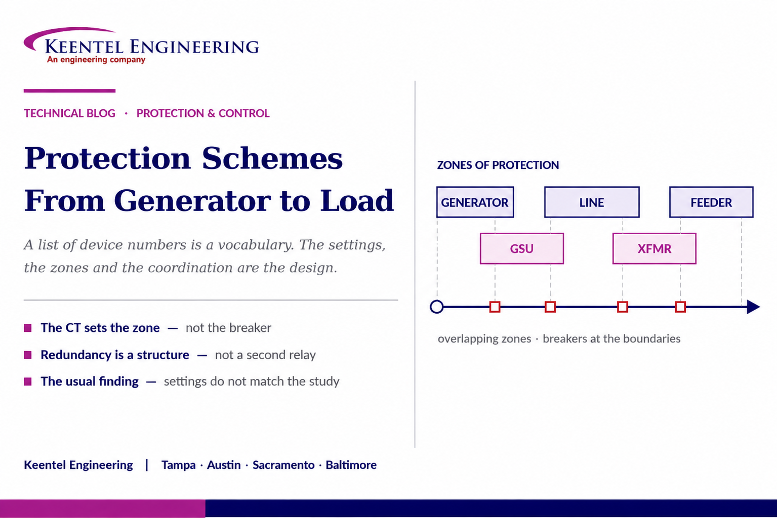
Power System Protection Schemes: From Generator to Load
September 01, 2026 | Blog
What the Device Numbers Actually Do, Where the Zones Meet, Why the Settings Are the Design, and How Protection Systems Really Fail
1. Executive Summary
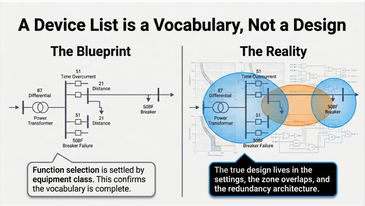
A single-line diagram annotated with device function numbers — 87 here, 51 there, 21 on the line, 50BF at the breaker — is the most recognisable artefact in power system protection. It is also the least informative one, because it shows what functions exist and says nothing about the four things that determine whether the protection works: where the zone boundaries fall, what the settings are, how the zones coordinate with each other, and what happens when the primary scheme fails.
Protection engineering is not function selection. Function selection is largely settled by equipment class and has been for decades — a generator gets differential, loss of field, reverse power, negative sequence and overexcitation; a transformer gets differential, restricted earth fault, and its mechanical protections; a transmission line gets distance or line differential with a communications scheme. The engineering is in the numbers behind those functions and in the relationships between them.
This paper works through the protection scheme from generator to load in that spirit. It covers zones and why the current transformer location defines them, the structure of primary and backup protection, what the device numbers actually mean and where they are commonly misread, equipment-by-equipment protection philosophy with the failure modes each function exists to catch, and then the four areas where real installations actually go wrong: instrument transformers, coordination settings that do not match the study of record, inverter-based resources invalidating conventional assumptions, and the maintenance and testing regime.
It closes with a misoperation taxonomy, three illustrative case scenarios, a twenty-five question FAQ, and a summary of the protection and control services Keentel provides.
The idea the chart cannot convey
Two substations can carry identical device number lists and have completely different protection quality. The difference is in the settings, the zone boundaries, the redundancy architecture, and whether any of it has been verified against the system as it exists today.
A protection scheme is a set of decisions, not a set of devices.
2. A Device List Is a Vocabulary, Not a Design
Function numbers come from the standard device function numbering system, which assigns numbers to functions and appends suffix letters to indicate the quantity or apparatus involved. It is a shared vocabulary that lets engineers on different continents read the same drawing. It is not a design method, and three things it cannot express are exactly the three things that matter most.
- Settings. A 51 with a 0.5 second time dial and a 51 with a 5 second time dial are the same symbol and different protection systems. Every number on a chart hides a set of pickup values, time characteristics, and logic that came from a study — or did not.
- Zone boundaries. A differential element protects whatever falls between its current transformers. Move a CT and the protected zone changes. The symbol does not move.
- Relationships. Whether zone 2 of a distance element coordinates with the adjacent line’s zone 1, whether the feeder relay coordinates with the fuse, and whether breaker failure timing coordinates
- with the remote backup are all invisible on the chart and are the entire substance of the design.
This is why a protection review that consists of confirming that all the expected functions are present is not a protection review. It confirms the vocabulary is complete.
3. Zones of Protection
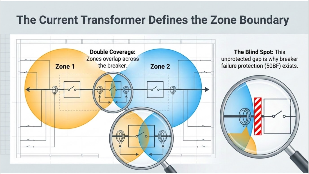
The organising principle of the entire discipline is that the power system is divided into overlapping zones, each bounded by circuit breakers, each with its own protection, and each overlapping its neighbours so that no point in the system is unprotected.
3.1 The Zone Boundary Is the Current Transformer
A zone is defined by the current transformers that feed the protection, not by the breaker. Where CTs are located on both sides of a breaker, the zones overlap across the breaker and every point is covered twice. Where a single CT set is shared, one side of the breaker falls in one zone and the other side in the other, and the small region between the CT and the breaker interrupting element belongs to a zone whose breaker cannot clear a fault there. That region is why breaker failure protection exists and why the CT arrangement question is asked at design rather than at commissioning.
3.2 Overlap, Gaps, and Additions
Zone gaps are almost never designed in. They appear when a system is modified: a bay is added to a bus, a transformer is replaced, a feeder is reconfigured, and the differential zone is not extended to include the new current transformers. The result is a section of primary plant protected only by remote backup, cleared in hundreds of milliseconds rather than tens, with the corresponding increase in equipment damage and incident energy. Section 19 works through exactly this scenario.
3.3 The Zones in a Typical System
From the machine outward: the generator zone bounded by the machine neutral and the generator breaker CTs; the generator step-up transformer zone, often combined with the generator into a unit zone; the high-voltage bus zone; the transmission line zone between the two line-end CTs; the receiving bus zone; the step-down transformer zone; the distribution bus; and the feeder zones. Each boundary is a design decision about CT placement, and each overlap is a deliberate redundancy.
4. Primary, Backup, and Redundancy
Every zone needs an answer to the question of what happens when its primary protection or its breaker fails to operate. There are three structural answers and most schemes use all three.
- Redundant primary protection. Two independent protection systems covering the same zone, ideally using different measuring principles, different relay hardware, separate current and voltage inputs, separate DC supplies, and separate trip coils. This is the standard on transmission and on generation of any significance, and it is the only arrangement that protects against a relay failing silently.
- Local backup by breaker failure protection. A scheme that starts a timer when a trip is issued and re-checks for current after the breaker should have cleared. If current persists, it trips everything else connected to that bus. Its timing is a coordination problem in its own right: too fast and it operates on a healthy breaker during slow clearing, too slow and the remote backup beats it.
- Remote backup. The protection at the far end of adjacent elements, reaching into this zone with a time delay. It is the last line and it clears far more of the system than necessary, which is why it is a backup and not a design objective.
The engineering judgment lies in how much independence is genuinely present. Two relays in the same panel, on the same DC circuit, sharing a CT core, tripping the same coil, are not two protection systems. They are one protection system with two relays in it, and a single fuse can remove both.
5. Reading Device Numbers Correctly
Several numbers on any protection chart are routinely misread, and the misreadings have consequences.
| Function | What it is | Common misreading |
|---|---|---|
| 87 (differential) | A unit protection comparing currents entering and leaving a defined zone. Suffixes identify the zone: generator, transformer, bus, line, motor | Treating all 87 elements as equivalent. Transformer differential must compensate for ratio, vector group and inrush; bus differential must survive CT saturation; line differential needs communications |
| 64 vs 51G vs 50N | Earth fault functions with different measuring principles — restricted earth fault, residual overcurrent, and neutral overcurrent are not interchangeable | Assuming any earth fault element covers any earth fault. Restricted earth fault is a unit function with a zone; residual overcurrent is a graded function |
| 51V | Voltage-restrained or voltage-controlled overcurrent, used on generators because fault current decays below full load current as the field collapses | Applying a plain 51 to a generator and expecting it to detect a sustained fault |
| 21 (distance) | An impedance-measuring element with multiple zones and characteristics, whose reach depends on the line impedance, the source impedance ratio, and infeed | Treating zone reach as a fixed percentage of line length regardless of infeed and fault resistance |
| 67/67N | Directional overcurrent — an overcurrent element supervised by a direction decision derived from a polarising quantity | Assuming the polarising source is always valid. On inverter-dominated systems the polarising quantities may not behave as assumed |
| 79 (reclosing) | Automatic reclosing, applicable where most faults are transient | Applying it without voltage or synchronism supervision where distributed generation may hold an island |
| 50BF | Breaker failure — local backup, not a form of overcurrent protection | Setting the timer without coordinating against remote backup and against breaker interrupting time plus margin |
| 24 (volts per hertz) | Overexcitation protection for generators and transformers, protecting against core saturation at low frequency or high voltage | Omitting it on the transformer because the generator has it, when the two see different conditions during islanded or start-up operation |
| 78 | Out-of-step, appearing both as generator pole slip and as system power swing blocking or tripping | Confusing power swing blocking, which prevents tripping, with out-of-step tripping, which causes it, in the same scheme |
6. Generator Protection
The generator is the most heavily protected element in the system, because it is the most expensive, the least replaceable, and uniquely vulnerable to abnormal operating conditions that are not faults at all.
6.1 Fault Protection
Differential protection covers stator phase faults across the machine zone. Stator earth fault protection is more subtle: on a high-impedance-grounded machine, earth fault current is deliberately limited to a few amperes, so the protection is voltage-based rather than current-based and covers roughly the upper ninety percent of the winding. Complete coverage of the last portion near the neutral requires an additional method — third-harmonic voltage comparison, or low-frequency voltage injection, which works even at standstill. Whether that coverage is provided is a design decision with cost and risk on both sides, and it should be a documented decision rather than an omission.
Rotor earth fault protection matters because a single rotor earth fault does no damage but a second one creates a shorted turn, unbalanced magnetic pull, and rapid mechanical destruction. It is a detection function, not a fault-clearing function, and it is often alarmed rather than tripped — which is defensible only if someone acts on the alarm.
6.2 Abnormal Operating Conditions
- Loss of field. The machine draws reactive power from the system, the rotor heats from induced currents, and the system voltage suffers. The setting derives from the machine capability curve and the steady-state stability limit, not from a template.
- Reverse power. Motoring on loss of prime mover, protecting the turbine rather than the generator, with settings that differ by an order of magnitude between machine types.
- Negative sequence. Unbalanced current induces double-frequency currents in the rotor body; the withstand is expressed as a machine-specific thermal capability, and the protection must be set to that machine’s value.
- Overexcitation. Volts-per-hertz protection with an inverse characteristic matched to the core capability, critical during start-up, shutdown, and load rejection.
- Frequency and voltage. Abnormal frequency protection must coordinate with turbine limits and, for inverter-based plant, with ride-through obligations that now prohibit tripping inside defined envelopes.
- Inadvertent energisation. Closing a breaker onto a machine at standstill, which conventional protection does not reliably detect; a dedicated supervised scheme covers it.
- Out-of-step and pole slip. Detecting loss of synchronism before the resulting torque transients damage the shaft.
7. Transformer Protection
Transformer protection combines electrical and mechanical measurement, and the mechanical devices are not secondary.
Differential protection is the primary electrical function, and it is harder than it looks. The element must compensate for the turns ratio, for the phase shift introduced by the winding connection, and for zero-sequence current that circulates in a delta winding and must be removed from the comparison. It must restrain during energisation inrush, which produces a large apparent differential current rich in second harmonic, and during overexcitation, which produces fifth harmonic. Restraint methods and their thresholds are settings, and disabling restraint to stop a nuisance operation — a genuinely common field expedient — removes the protection’s ability to distinguish inrush from an internal fault.
Restricted earth fault provides sensitive detection of winding earth faults close to the neutral where differential sensitivity falls away. It is a unit function with its own zone and its own CT requirements.
The mechanical protections detect what electrical measurement cannot see early. Gas accumulation and oil surge detection responds to incipient insulation breakdown before it becomes an electrical fault.
Pressure relief responds to a rapid internal pressure rise. Winding and oil temperature protection responds to thermal overload. Sudden pressure detection is fast and, on some designs, can operate on external through-faults, which is why its application and supervision deserve engineering attention rather than default settings.
Through-fault withstand is the design constraint most often missed. A transformer has a defined capability for external fault current versus duration, and the upstream protection must clear within it. A coordination study that achieves selectivity but leaves the transformer outside its through-fault capability has traded one failure for another.
8. Transmission Line Protection
Line protection is where communications, coordination, and measurement principle interact most tightly.
8.1 Distance and Line Differential
Distance protection measures apparent impedance and compares it to zone characteristics. Zone one is set to under-reach the remote terminal so it can operate instantaneously without coordination; zone two over-reaches to cover the remainder with time delay; zone three provides remote backup. The reach settings depend on line impedance, mutual coupling with parallel circuits, fault resistance, and infeed from intermediate sources — and infeed is why a zone setting that was correct at commissioning can become incorrect when generation is added at an intermediate bus.
Line current differential compares currents at both ends and is inherently selective, immune to infeed, immune to power swings, and unaffected by source impedance ratio. Its cost is a communications channel and its dependence on that channel’s availability and timing. On lines terminating at inverter-based plants it has become the preferred primary scheme for the reasons in Section 14.
8.2 Communications-Assisted Schemes
Permissive and blocking schemes convert an over-reaching or under-reaching element into fast clearing for the whole line by exchanging a signal with the remote end. The choice between permissive over-reach, permissive under-reach, directional comparison blocking, and unblocking is a function of channel type, channel reliability, and the consequences of channel failure — a blocking scheme fails toward over-tripping, a permissive scheme fails toward under-tripping, and neither failure mode is universally preferable.
Weak infeed and echo logic exists for terminals that cannot produce a reliable directional decision or sufficient current. It was originally for weak sources; it is now routinely needed at inverter-based plants.
8.3 Swings, Reclosing, and Location
Power swing blocking prevents distance elements from tripping during stable swings, while out-of-step tripping deliberately separates the system at a chosen location during unstable swings. Both must be set from stability studies rather than from defaults, and the two functions must be coordinated with each other.
Autoreclosing exploits the fact that most transmission faults are transient. Its supervision — synchronism check, voltage check, dead-line and dead-bus logic — is the part that prevents it from closing into a fault or out of synchronism. Fault location, whether impedance-based or travelling-wave, is an operational tool rather than a protection function, and its accuracy depends on the same line constants the distance settings use.
9. Bus Protection
A bus fault is the most severe fault in a substation because it is fed from every connected source simultaneously and because clearing it means removing everything connected. Bus protection is therefore both critical and unusually sensitive to error, since a misoperation removes the entire substation.
Low-impedance differential compares currents from all connections using the relay’s own restraint characteristic and can accommodate dissimilar CT ratios. Its main design challenge is CT saturation during external faults with heavy DC offset, which produces a false differential quantity; the countermeasure is saturation detection logic and appropriate restraint. High-impedance differential requires matched CT ratios and dedicated cores but is inherently secure against saturation through its operating principle. Both remain in service and the choice is a genuine engineering decision.
A check zone — a second, coarser differential covering the whole bus regardless of section — supervises the main zones so that a single CT or logic error in one zone cannot trip the bus alone. On sectionalised or breaker-and-a-half arrangements, dynamic zone selection based on isolator position introduces a dependency on auxiliary contacts, which are a mechanical device in a protection path and should be treated as such.
10. Distribution Feeder Protection
Feeder protection is nominally the simplest part of the system and has become the most rapidly changing, because the assumption it was built on — that power flows one way from the substation — no longer holds.
The traditional scheme is graded overcurrent and earth fault with reclosing, coordinated against downstream fuses and reclosers. The classic design choice is between fuse saving, where the recloser operates fast to clear transient faults before the fuse melts, and fuse blowing, where the fuse operates first and permanent faults are sectionalised without a system-wide voltage dip. The choice trades customer momentary interruptions against sustained ones and is a policy decision as much as an engineering one.
Distributed generation on the feeder disturbs all of it. Fault current contribution from the distributed source reduces the current seen by the substation relay for downstream faults, extending clearing time. Fault current flowing from the feeder into a fault on an adjacent feeder can cause sympathetic tripping. Reclosing onto an energised island formed by distributed generation risks out-of-phase closing that damages both the generation and the network. And an inverter-based source contributes so little fault current that overcurrent elements may not see it at all while it is nonetheless capable of sustaining an island.
The remedies are known: directional supervision on feeder relays, voltage supervision and reclose blocking, transfer trip where the exposure warrants it, and coordination studies that model the distributed generation rather than treating it as negative load. What is often missing is the trigger — nobody re-runs the coordination study when the fifth interconnection application on a feeder is approved.
11. Motors, Capacitors, and Compensation
11.1 Motors
Motor protection is dominated by thermal modelling rather than by fault detection. The thermal element tracks heating from both positive- and negative-sequence current, because negative-sequence current heats the rotor far more effectively than positive-sequence current does. Locked rotor and stall protection must distinguish a long legitimate start from a failure to accelerate, which is why start supervision uses speed switches or current-versus-time logic rather than a single threshold. Phase unbalance and single phasing, loss of load, and starts-per-hour limits complete the set. Bearing temperature and vibration are condition monitoring rather than protection, and treating them as protection inputs requires a deliberate decision about tripping versus alarming.
11.2 Capacitor Banks
Capacitor bank protection centres on unbalance detection, because the failure mode is progressive loss of individual capacitor units or elements. Unbalance protection detects the resulting voltage or current asymmetry and must distinguish a single element failure, which is alarmed, from a cascade approaching overvoltage on the remaining units, which is tripped. Sensitivity has to be set against the inherent unbalance of the bank and the ambient variation, which is why generic settings are unsuitable. Harmonic overload protection matters where the bank participates in a resonance, and switching restraint addresses the inrush and restrike duty that back-to-back switching imposes.
11.3 Series and Shunt Compensation, and HVDC
Series capacitors change the impedance a distance relay measures and can cause voltage inversion, current inversion, and sub-harmonic transients that defeat conventional distance elements. Lines with series compensation require protection specifically applied for it. Static compensators and converter stations carry their own protection sets — converter and valve protection, DC-side earth fault, pole-to-ground fault detection, smoothing reactor protection — whose interaction with the AC system protection is a study in its own right.
12. System-Wide Schemes
Above the equipment level sit the schemes that protect the system rather than any asset.
- Under-frequency and under-voltage load shedding, which trade load for system survival and whose settings are set regionally rather than by the owner, and which must coordinate with generation ride-through envelopes so that generation does not disconnect before load sheds.
- Remedial action or special protection schemes, which take pre-planned action on detection of defined conditions to preserve stability or respect a transfer limit. They are among the highest-consequence installations in any system and carry their own review, documentation, and periodic verification obligations.
- Wide-area protection using synchronised measurement, which is increasingly the layer that detects oscillations and stress conditions that local protection cannot see.
- Black start and system restoration, where protection settings appropriate for a fully interconnected network can be entirely wrong for a lightly loaded, low-fault-current restoration path.
13. Instrument Transformers: The Common Root Cause
Protection acts on what its instrument transformers tell it. More field problems trace to those inputs than to the relays themselves, and the failure modes are consistent.
- Ratio and polarity errors. A CT installed with reversed polarity or a ratio different from the setting produces differential quantities that either operate on load or fail to operate on a fault. Verification is a commissioning test, not a drawing check.
- Saturation. A CT with insufficient accuracy voltage rating for the connected burden and the offset fault current will saturate, and a saturated CT delivers a distorted, reduced secondary current at the moment the protection most needs an accurate one. Accuracy class, burden and the expected DC offset must be evaluated together, and the calculation belongs in the design record.
- Shared cores. Metering and protection cores have different requirements. Sharing a core between functions, or between two supposedly independent protection systems, imports a common-mode failure into an arrangement that was intended to be redundant.
- Voltage transformer fuse failure. Loss of a voltage input can cause distance, directional, and voltage-restrained elements to misoperate. Fuse failure detection that blocks the affected elements is standard and its correct configuration is worth verifying.
- Capacitive voltage transformer transients. The transient response of a CVT following a voltage collapse is not instantaneous, which affects distance element behaviour at high source impedance ratios and requires specific relay logic.
- Wiring and grounding. A CT circuit grounded at more than one point, an open CT secondary, or a shorting screw left in place after testing each produce a distinct and well-documented failure. The last of these is a leading cause of protection being absent without anyone knowing.
14. Where Inverter-Based Resources Break the Assumptions
Conventional protection assumes sources behave like synchronous machines: large fault current, a defined and stable relationship between sequence quantities, and behaviour set by impedance rather than by control code. Inverter-based resources satisfy none of those assumptions.
- Fault current is limited by control to a small multiple of rated current, for a controlled duration. Overcurrent elements may never reach pickup and breaker failure current detectors may not see enough current to operate.
- Negative-sequence behaviour is a property of the converter’s control implementation. Where the converter has no dedicated negative-sequence regulator, the relationship between negative-sequence current and voltage is not fixed, which is precisely the quantity negative-sequence directional elements use to decide direction.
- Phase selection logic relies on angular relationships among sequence currents that hold for networks of impedances. At a converter, both the positive- and negative-sequence angles are control outputs, so the relationships do not hold.
- Distance elements face very high source impedance ratios and current-limited infeed, degrading reach accuracy and resistive coverage.
- Zero-sequence current at the point of interconnection comes from the interconnection transformer grounding, not from the inverters, and modelling it as a plant contribution produces incorrect ground element analysis.
The practical responses are line current differential as the primary scheme, communications-assisted logic with weak-infeed and echo provisions, reduced reliance on negative-sequence direction at inverter terminals, and evaluation of the affected elements against time-domain simulation rather than a single phasor result. The ride-through standards now in force add a further constraint: protection settings must not defeat the ride-through requirement, which makes protection settings and grid-code compliance the same conversation.
15. Coordination and the Settings Behind the Chart
Coordination is the discipline of ensuring that for any fault, the device closest to it operates first and everything upstream holds. It is expressed on time-current curves with a coordination time interval that accounts for the upstream device’s operating time, breaker interrupting time, relay overtravel, and a safety margin.
Four tensions make it a genuine engineering exercise rather than a drafting one.
- Coordination versus equipment protection. Delaying an upstream device to achieve selectivity increases the energy the equipment absorbs during a fault and may exceed a transformer’s through-fault capability or a cable’s thermal limit.
- Coordination versus arc flash. Time delay is incident energy. A scheme optimised purely for selectivity can produce hazard levels that make maintenance impractical, which is why maintenance-mode settings and instantaneous zone-selective schemes exist.
- Coordination versus series ratings. A series combination rating works because the upstream device operates — the opposite of what coordination seeks. Where selective coordination is required by code for emergency, legally required standby, or critical operations power systems, series ratings are not an available answer.
- Coordination versus reality. Settings are derived from a study that assumed a system configuration. Configuration changes — an added source, a closed tie, a replaced transformer, an added distributed generator — invalidate it silently.
Which leads to the single most consistent finding across protection reviews: the settings installed in the relays do not match the current revision of the coordination study. Sometimes the study was revised and never implemented; sometimes the settings were changed in the field and the study never updated. Either way the facility is operating on an unverified selectivity claim, and its arc flash labels — which are computed from the settings the study assumed — are wrong.
16. Communications, IEC 61850, and the Process Bus
Modern protection is increasingly a communications system. That brings real benefits and a new class of failure mode.
Station bus messaging replaces hard-wired interlocking and inter-relay signalling with published messages, which reduces wiring, makes schemes reconfigurable, and introduces a dependency on network configuration and on the supervision that detects a message that has stopped arriving. Process bus extends this to the instrument transformer interface, replacing copper from the switchyard with digitised sampled values — which removes CT burden and open-circuit hazards and adds a dependency on time synchronisation.
Three engineering consequences follow. Time synchronisation becomes a protection component: loss of a common time reference can disable functions that depend on synchronised sampling, and the synchronisation architecture needs the same redundancy thinking as the DC supply. Network redundancy protocols must be applied so that a single link or switch failure does not remove protection. And configuration management becomes a protection discipline: a scheme defined in configuration files rather than in wiring is easier to change and easier to change wrongly, and the configuration is now part of the settings record that must be controlled, versioned, and verified.
17. Maintenance, Testing, and the Compliance Frame
A protection system is a latent-failure system. It sits idle and is called upon rarely, so a failure is undetectable until the moment it matters. That is the entire justification for a maintenance and testing programme, and for the reliability standards that require one.
- Protection system maintenance obligations define components, intervals, and activities, with intervals depending on the degree of self-monitoring the equipment provides. Documentation of the programme and evidence of its execution are as much a part of compliance as the work itself.
- Relay loadability requirements prevent protection from tripping on load or on recoverable swings, which addresses a documented contributor to cascading outages.
- Coordination of generator voltage regulating controls with protection prevents the excitation limiters and the protection from working against each other.
- Generator relay loadability and generator protection coordination requirements address the machine-side equivalents.
- Misoperation analysis obligations require identifying protection system misoperations, determining cause, and implementing corrective action — which turns individual events into the data set that improves the fleet.
- Ride-through and disturbance monitoring standards for inverter-based resources now constrain what protection settings are permitted, and provide the recorded data on which performance is demonstrated.
- Remedial action scheme requirements impose review, documentation, and periodic testing on those schemes specifically.
Commissioning deserves its own mention. End-to-end testing that proves the whole scheme — from primary injection through the relay logic to the breaker trip coil, including communications-assisted logic tested with both terminals live — is what verifies that the design as built matches the design as drawn. Element-by-element bench testing does not
18. Why Protection Systems Misoperate
Misoperation causes recur with striking consistency, and the distribution is not what most people expect: the relays themselves are rarely the problem.
| Cause category | Typical manifestation | What prevents it |
|---|---|---|
| Incorrect settings, logic, or design errors | Settings that do not match the current study; zone reach errors; logic that behaves correctly in every case anyone thought to test | Independent settings review against the study of record, and end-to-end commissioning of the logic rather than the elements |
| As-left personnel error | Test switches left open, shorting screws left in, links not restored, settings group left in a test group | Formal as-left verification, a controlled restoration checklist, and post-work status verification from the control system |
| Instrument transformer problems | Wrong ratio, reversed polarity, saturation on offset faults, shared cores between supposedly redundant systems, VT fuse failure | CT saturation calculation in the design record, primary injection at commissioning, and polarity verification per circuit |
| Communications failures | Channel loss in permissive or blocking schemes, message loss on station bus, loss of time synchronisation on process bus | Channel supervision, defined and tested fail-safe behaviour, redundant paths, and treating time sync as a protection component |
| DC supply problems | Battery or charger failure, loss of a DC circuit removing more protection than intended, undetected open trip coil | DC circuit segregation between redundant systems, trip circuit supervision, and battery maintenance |
| Unmodelled system change | Added generation changing infeed and distance reach; added distributed generation on a radial feeder; closed tie changing fault distribution | A change-control trigger requiring re-study on defined system changes rather than on a calendar |
| Maintenance and testing gaps | Latent failure in a component that was never exercised because it is not part of a routine test | A maintenance programme scoped to components rather than to devices, with intervals matched to self-monitoring capability |
19. Case Studies
The following scenarios are composite and illustrative. They are constructed from patterns that recur across utility, industrial, and generation facilities to show how these failures develop and how they are found. They do not describe any specific client, site, project, manufacturer, or utility.
19.1 Case A — The Bay That Was Outside the Zone
Situation. A substation bus was extended by one bay to serve a new load. The work was executed competently: the bay was built, the feeder relay was installed and set, the coordination study was updated for the new feeder, and the addition was commissioned without incident.
What the review found. The bus differential zone had not been extended to include the new bay’s current transformers. The differential element continued to compare the currents it had always compared, so the new bay’s contribution to a bus fault was unmeasured — and, more seriously, a fault between the new bay’s CT and its breaker fell outside every differential zone in the station. The condition produced no alarm and no symptom, because a differential element that is missing an input still balances under load.
Exposure. A fault in that region would have been cleared only by remote backup, in hundreds of milliseconds rather than tens, with correspondingly higher equipment damage and incident energy. The station’s arc flash labels, computed on the assumption of bus differential clearing, understated the hazard in that area.
Remedy. The differential zone was extended to include the new CTs, with the ratio and restraint settings recalculated for the revised zone, and the check zone updated to match. Primary injection verified the new inputs. The arc flash study was reissued and labels replaced.
Lesson. A zone boundary is defined by current transformers, and a project that adds primary plant changes zone boundaries whether or not anyone updates the protection. Make extension of unit protection zones an explicit checklist item on every project that adds or relocates a bay, and verify by primary injection rather than by drawing review.
19.2 Case B — The Feeder That Kept the Island Alive
Situation. A distribution feeder with a traditional overcurrent and reclosing scheme accumulated distributed generation over several years through successive interconnection applications, each individually small and each individually studied for steady-state impact. The protection scheme was never revisited.
What the review found. Three compounding problems. The distributed generation contribution reduced the current the substation relay measured for downstream faults, extending clearing times beyond the values the coordination study assumed. Fault current flowing from this feeder toward a fault on an adjacent feeder was sufficient to operate non-directional elements, creating sympathetic tripping exposure. And the reclosing scheme had no voltage supervision, so a reclose onto a feeder section energised by the distributed generation could have closed out of synchronism.
Exposure. Slower clearing for downstream faults; loss of a healthy feeder during faults on an adjacent one; and, in the worst case, out-of-phase closing damaging both the distributed generation and network equipment, with the associated liability question about who caused it.
Remedy. Directional supervision was added to the feeder relays, voltage supervision and reclose blocking were implemented so that reclosing cannot occur into an energised line section, and the coordination study was rebuilt with the distributed generation modelled as a fault current source rather than as negative load. A change-control trigger was established requiring protection re-study when cumulative interconnected capacity on a feeder crosses a defined threshold.
Lesson. Radial feeder protection assumes one-way power flow. Distributed generation invalidates that assumption incrementally, and no single interconnection application is large enough to trigger a review. The trigger has to be defined in advance and applied cumulatively.
19.3 Case C — The Directional Element That Would Not Decide
Situation. A transmission line was protected by a permissive over-reaching scheme with negative-sequence directional supervision at both terminals — a conventional and well-proven arrangement. A large inverter-based generating facility was subsequently connected at one terminal.
What the review found. The negative-sequence directional element at the inverter terminal could not be relied upon. The converter’s negative-sequence current was not regulated to a defined angular relationship with negative-sequence voltage, so the quantity the directional element uses to decide direction was neither stable nor within the expected range during the first cycles of a fault — which is precisely when the scheme needs a decision. Time-domain simulation with the manufacturer’s validated model confirmed the behaviour that a phasor short-circuit study had not revealed, because the phasor model represented the converter as a fixed-angle sequence source.
Exposure. Absent or incorrect directional declarations at one terminal defeat a permissive scheme, converting fast clearing into delayed zone two clearing, or in the reverse-declaration case creating exposure to incorrect operation. Neither outcome would have been visible until a real fault occurred.
Remedy. Line current differential was made the primary scheme, since it does not rely on sequence angle to establish direction. Weak-infeed and echo logic was added to the communications scheme. The converter’s negative-sequence injection configuration was confirmed against the interconnection performance requirements and recorded as a controlled setting, with a change-control trigger requiring protection re-evaluation if it is altered.
Lesson.
Protection schemes carry embedded assumptions about how sources behave. Inverter-based resources satisfy some of those assumptions and not others, and which ones depend on the converter’s control implementation and configuration — not on the technology class. Evaluate the affected elements in the time domain, using the manufacturer’s validated model at the configuration actually deployed.
20. Reading the Chart Correctly
The list is complete and the design is not
Confirming that every expected function is present verifies vocabulary, not protection. The settings, the zone boundaries, and the coordination relationships are the design, and none of them appear on the chart.
Actual schemes vary, and the variation is the engineering
Function selection depends on system voltage, equipment rating, grounding method, fault current availability, utility practice, and the consequence of failure. A chart shows what is typical; a design states what is required and why. Both matter, and the second is the deliverable.
Backup is a structure, not a second device
Redundancy is real only to the extent that the two paths are independent — separate inputs, separate DC, separate trip coils, ideally different measuring principles. Two relays sharing a CT core and a fuse are one protection system.
The chart shows a system that no longer exists everywhere
One-way power flow on distribution, synchronous sources with predictable fault behaviour, and hard-wired signalling were all safe assumptions and are no longer universal. Distributed and inverter-based generation, communications-based schemes, and digitised instrument transformer interfaces each change what the same device number does in practice.
21. Keentel Protection and Control Services
Protection and control is core practice at Keentel Engineering. We work from the studies that generate the settings through to the commissioning that proves them, across generation, transmission, distribution, industrial, and mission-critical facilities.
21.1 Protection Studies and Settings
- Short-circuit and fault current studies across all operating configurations, with inverter-based resources represented as current-limited sources rather than equivalent machines.
- Protective device coordination and selectivity studies, including selective coordination where required by code for emergency, legally required standby, and critical operations power systems.
- Relay setting calculations and settings files for generator, transformer, bus, line, feeder, motor, and capacitor protection, prepared against the study of record and issued in a form that can be loaded and verified.
- Arc-flash incident energy analysis and labelling, reissued in step with the underlying short-circuit and coordination work, including maintenance-mode and zone-selective evaluation where hazard reduction is required.
- Current and voltage transformer sizing, accuracy class and burden calculations, and saturation assessment for the expected offset fault current.
21.2 Protection Scheme Design
- Protection philosophy development, zone definition, redundancy architecture, and primary and backup scheme selection, documented as a design basis rather than inherited from a template.
- Transmission line scheme design including distance, line current differential, permissive and blocking communications schemes, weak-infeed and echo logic, power swing blocking and out-of-step tripping, and reclosing supervision.
- Bus differential design including low- and high-impedance selection, check zone arrangement, and dynamic zone selection.
- Generator and generator step-up protection, including complete stator earth fault coverage decisions, inadvertent energisation, and coordination with excitation limiters.
- Distribution feeder protection with distributed generation, including directional supervision, reclose blocking, transfer trip evaluation, and coordination rebuilt with distributed sources modelled as fault current contributors.
- Relay panel, schematic, wiring, and DC system design, and substation automation and SCADA integration.
21.3 Digital Substation and Communications
- IEC 61850 station and process bus architecture, configuration development, network redundancy, and time synchronisation design treated as a protection component.
- Configuration management and version control for settings and configuration files, so that the scheme in service is the scheme that was engineered.
21.4 Compliance, Commissioning, and Investigation
- NERC protection-related compliance support including protection system maintenance programmes, relay loadability, generator protection coordination, misoperation analysis, remedial action scheme documentation, and the ride-through and disturbance monitoring standards now constraining protection settings on inverter-based resources.
- Commissioning specification, test procedure development, end-to-end scheme testing, and as-left verification.
- Settings audits comparing installed settings against the study of record, and protection reviews on system changes that invalidate prior work.
- Misoperation and failure investigation, including event record and oscillography analysis, root cause determination, and corrective action development.
Keentel Engineering holds a Florida Certificate of Authorization and maintains offices in Tampa, Austin, Sacramento, and Baltimore, supporting projects across the interconnections.
22. Frequently Asked Questions
A zone is a region of the power system with its own protection, bounded by circuit breakers. Its boundary is defined by the current transformers that feed the protection, not by the breaker itself. Where CTs exist on both sides of a breaker the adjacent zones overlap and every point is covered twice; where a single CT set is shared, a small region between the CT and the breaker interrupting element belongs to a zone whose breaker cannot clear a fault there.
So that no point in the system is unprotected. A gap between zones would leave primary plant covered only by remote backup, clearing in hundreds of milliseconds instead of tens. Overlap is a deliberate redundancy and it costs an additional CT set at each boundary.
Through modification, not through design. A bay is added, a transformer replaced, a bus reconfigured, and the differential zone is not extended to include the new current transformers. A differential element missing an input still balances under load, so there is no alarm and no symptom until a fault occurs in the unprotected region.
Independence across the whole path: separate current and voltage inputs from separate CT cores, separate relays, separate DC supplies, separate trip coils, and ideally different measuring principles. Two relays in one panel sharing a CT core, a DC circuit and a trip coil are one protection system with two relays in it, and a single fuse removes both.
Local backup. It starts a timer when a trip is issued and re-checks for current after the breaker should have cleared; if current persists it trips everything else on that bus. Its timing is a coordination problem in itself — too fast and it operates on a healthy breaker during slow clearing, too slow and remote backup beats it.
No, and treating them as equivalent causes real problems. Transformer differential must compensate for turns ratio, winding phase shift and zero-sequence circulation, and must restrain on inrush and overexcitation. Bus differential must survive CT saturation during external faults. Line differential needs a communications channel and timing. Generator differential is comparatively simple. The symbol is the same; the engineering is not.
Because generator fault current decays as the field collapses and can fall below full load current within seconds. A plain overcurrent element set above load will drop out on a sustained fault. Voltage restraint or voltage control makes the element sensitive when voltage is depressed, which is when a fault is present.
On a high-impedance-grounded machine, earth fault current is deliberately limited, so the protection measures neutral displacement voltage — and that voltage approaches zero for faults near the neutral. Complete coverage requires an additional method such as third-harmonic voltage comparison or low-frequency voltage injection. Whether to provide it is a documented cost-and-risk decision, not an omission.
Because one rotor earth fault causes no damage on its own. A second fault creates a shorted turn, unbalanced magnetic pull, and rapid mechanical damage. Alarming is defensible only where someone reliably acts on the alarm; if that is not true, the design decision should be revisited.
Energisation inrush produces a large apparent differential current rich in second harmonic, and overexcitation produces fifth harmonic. Restraint uses that harmonic content to distinguish these conditions from an internal fault. Disabling restraint to stop nuisance operations — a common field expedient — removes the element’s ability to tell inrush from a fault.
A transformer has a defined capability for external fault current versus duration. Upstream protection must clear within it. A coordination scheme that achieves selectivity by delaying upstream devices can push the transformer outside that capability, trading a selectivity problem for an equipment damage problem.
Because they detect what electrical measurement cannot see early. Gas accumulation and oil surge detection respond to incipient insulation breakdown before it becomes an electrical fault; pressure relief responds to rapid internal pressure rise. They frequently provide the earliest warning available, and sudden pressure devices in particular deserve engineering attention on application and supervision rather than default settings.
So it can operate instantaneously without coordinating with anything. Measurement error, line constant uncertainty, and fault resistance mean an element set exactly to the line length would sometimes see beyond it. Under-reaching guarantees that anything zone one sees is on this line; zone two with time delay covers the remainder.
Infeed, most commonly. Generation added at an intermediate bus changes the apparent impedance the relay measures for faults beyond that point. Line reconductoring, series compensation, and changes to parallel circuit mutual coupling do the same. Settings correct at commissioning become incorrect without anyone touching the relay.
By how you want the scheme to fail. A blocking scheme fails toward over-tripping when the channel is lost; a permissive scheme fails toward under-tripping. The right answer depends on channel type and reliability and on the relative consequence of an unnecessary trip versus delayed clearing at that location.
Low impedance accommodates dissimilar CT ratios and uses relay restraint logic, with CT saturation on offset external faults as its main design challenge. High impedance is inherently secure against saturation by its operating principle but requires matched ratios and dedicated cores. Both remain valid; the choice depends on the bus arrangement and the CT situation.
Fuse saving operates a recloser fast to clear transient faults before the fuse melts, trading momentary interruptions for fewer sustained ones. Fuse blowing lets the fuse operate first, sectionalising permanent faults without a system-wide dip. It is a policy decision about which interruption type customers tolerate better, informed by the actual transient fault fraction on that feeder.
Three things. It reduces the current the substation relay sees for downstream faults, extending clearing time. It can push current toward faults on adjacent feeders, creating sympathetic tripping exposure on non-directional elements. And it can sustain an island, so reclosing without voltage supervision risks out-of-phase closing. Remedies are directional supervision, voltage-supervised reclose blocking, transfer trip where warranted, and coordination studies that model the generation as a source.
Because conventional protection assumes synchronous sources: large fault current, stable relationships among sequence quantities, and behaviour set by impedance. A converter is current-limited to a small multiple of rating, its sequence behaviour is a property of its control code and configuration, and both its positive- and negative-sequence angles are control outputs rather than impedance consequences. Overcurrent, negative-sequence directional, and phase selection are all affected.
Line current differential as the primary scheme, because it compares terminal currents and does not depend on sequence angle to establish direction, supplemented by communications-assisted logic with weak-infeed and echo provisions for the case where the inverter terminal cannot make a reliable directional declaration.
Several compete, but CT saturation and ratio or polarity errors dominate. A CT with insufficient accuracy voltage rating for its burden and the expected offset fault current delivers a distorted, reduced secondary current exactly when accuracy matters most. Ratio and polarity errors produce differential quantities that either operate on load or fail to operate on a fault. Both are caught by design calculation and by primary injection at commissioning.
That the settings installed in the relays do not match the current revision of the coordination study. Either the study was revised and never implemented, or the settings were changed in the field and the study never updated. The facility is then operating on an unverified selectivity claim, and its arc flash labels — computed from the settings the study assumed — are wrong.
They remove copper and add dependencies. Station bus messaging replaces wiring with published messages, requiring supervision that detects a message that has stopped arriving. Process bus digitises the instrument transformer interface, which removes burden and open-circuit hazards but makes time synchronisation a protection component needing the same redundancy thinking as the DC supply. And configuration files become part of the settings record, requiring version control and verification.
Rarely because the relay failed. The recurring causes are incorrect settings or logic, as-left personnel error such as test switches left open or shorting screws left in, instrument transformer problems, communications failures, DC supply problems, unmodelled system changes that invalidated the settings, and latent failures in components that routine testing never exercises.
System changes rather than a calendar: any utility source change, transformer replacement, service upsize, added generation or distributed generation, feeder reconfiguration, change in normal operating configuration, or added primary plant that alters a zone boundary. A periodic refresh is a reasonable backstop, but the change triggers are what actually keep the settings valid — and the arc flash study must be reissued whenever the protection study changes.
References and Further Reading
The following are referenced by subject in the body of this document. The current published edition of each standard or guide governs its own content, and manufacturer application guidance for the specific relays and equipment selected governs any application decision.
Device Numbering and General Practice
- IEEE Std C37.2, Standard for Electrical Power System Device Function Numbers, Acronyms, and Contact Designations — the source of the device numbers used throughout this document — IEEE Standards Association
https://standards.ieee.org/ - IEEE Std 242 (Buff Book), Recommended Practice for Protection and Coordination of Industrial and Commercial Power Systems, and the IEEE 3004 series of protection recommended practices — IEEE Standards Association
https://standards.ieee.org/ - IEEE Std 3002.3, Recommended Practice for Conducting Short-Circuit Studies and Analysis, and IEEE Std 1584, Guide for Performing Arc-Flash Hazard Calculations — IEEE Standards Association
https://standards.ieee.org/
Equipment Protection Guides
- IEEE Std C37.102, Guide for AC Generator Protection, and C37.101, Guide for Generator Ground Protection — IEEE Standards Association
https://standards.ieee.org/ - IEEE Std C37.91, Guide for Protecting Power Transformers, and IEEE Std C57.109, Guide for Liquid-Immersed Transformer Through-Fault-Current Duration — IEEE Standards Association
https://standards.ieee.org/ - IEEE Std C37.113, Guide for Protective Relay Applications to Transmission Lines, and C37.234, Guide for Protective Relay Applications to Power System Buses — IEEE Standards Association
https://standards.ieee.org/ - IEEE Std C37.230, Guide for Protective Relay Applications to Distribution Lines; C37.96, Guide for AC Motor Protection; C37.99, Guide for the Protection of Shunt Capacitor Banks — IEEE Standards Association
https://standards.ieee.org/ - IEEE Std C37.119, Guide for Breaker Failure Protection of Power Circuit Breakers, and C37.104, Guide for Automatic Reclosing on AC Distribution and Transmission Lines — IEEE Standards Association
https://standards.ieee.org/ - IEEE Std C57.13, Standard Requirements for Instrument Transformers, and C37.110, Guide for the Application of Current Transformers Used for Protective Relaying Purposes — IEEE Standards Association
https://standards.ieee.org/
Inverter-Based Resources, Communications, and Compliance
- IEEE Std 2800, Standard for Interconnection and Interoperability of Inverter-Based Resources Interconnecting with Associated Transmission Electric Power Systems — IEEE Standards Association
https://standards.ieee.org/ieee/2800/10453/ - IEC 61850 series, Communication networks and systems for power utility automation, and IEEE Std C37.238, Standard Profile for Use of IEEE 1588 Precision Time Protocol in Power System Applications — IEC and IEEE Standards Association
https://webstore.iec.ch/ - NERC Reliability Standards — including the PRC series covering protection system maintenance, relay loadability, generator protection coordination, misoperation analysis, remedial action schemes, and the ride-through and disturbance monitoring requirements applicable to inverter-based resources — North American Electric Reliability Corporation
https://www.nerc.com/pa/Stand/Pages/ReliabilityStandards.aspx - NFPA 70, National Electrical Code — including the selective coordination requirements applicable to emergency, legally required standby, and critical operations power systems, and NFPA 70E for electrical safety in the workplace — National Fire Protection Association
https://www.nfpa.org/
Notice and Disclaimer
This document is original technical content prepared by Keentel Engineering LLC for general professional information. It is not project-specific engineering advice and does not constitute a protection design, a settings recommendation, a study, or a compliance determination for any installation. Protection schemes and settings must be developed from project-specific analysis using verified system, equipment, and as-built data, and must satisfy the applicable manufacturer, utility, and regulatory requirements.
Protection function selection described here is typical rather than prescriptive. Actual schemes vary with system voltage, equipment rating, grounding method, available fault current, utility practice, and the consequence of failure, and device numbering conventions and function availability differ between manufacturers and relay platforms.
The case studies in Section 19 are composite and illustrative. They are constructed from patterns that recur across the industry to demonstrate how these failures develop and how they are found. They do not describe any specific client, site, project, manufacturer, or utility, and no inference should be drawn about any actual installation or party.
Keentel Engineering LLC is an independent engineering consultancy. Reference to any standard, code, industry organisation, regulator, or equipment category in this document does not imply affiliation with, endorsement by, or sponsorship from any such organisation or manufacturer.

About the Author:
Sandip "Sonny" R. Patel, P.E.
IEEE Senior Member · Founder & CEO, Keentel Engineering
In 1995, Sonny Patel earned his Electrical Engineering degree from the University of Illinois. But degrees don't build legacies — action does.
For three decades, he has worked the power industry from every side of the table: 16 years as a utility engineer at Exelon/Commonwealth Edison; generation leadership across hydroelectric, industrial steam turbine, and a 9 GW renewable fleet; NERC Regional Entity Senior Compliance Engineer and Audit Team Lead, auditing some of the nation's largest utilities; and testing and commissioning lead on equipment up to 765 kV — the very top of the North American grid.Utility. Generator. Regulator. Consultant. Few engineers have seen all four seats. Fewer still have sat in them.
His experience spans nuclear, hydro, conventional generation, renewables, oil and gas, mining — and today's data centers, where he is authoring a three-book series on data center design. He is a Licensed Professional Engineer in six states and a Licensed Electrical Contractor in Florida (Unlimited EC) — he doesn't just design the work; he's qualified to stand behind its execution.Today, as Founder and CEO of Keentel Engineering, Sonny leads a nationwide team of engineers delivering substation design, power system studies, NERC compliance, and commissioning — done right, coast to coast.Three decades. Every side of the table. One standard: accountable engineering.
Services

Let's Discuss Your Project
Let's book a call to discuss your electrical engineering project that we can help you with.
About the Author:
Sandip "Sonny" R. Patel, P.E.
IEEE Senior Member · Founder & CEO, Keentel Engineering
In 1995, Sonny Patel earned his Electrical Engineering degree from the University of Illinois. But degrees don't build legacies — action does.
For three decades, he has worked the power industry from every side of the table: 16 years as a utility engineer at Exelon/Commonwealth Edison; generation leadership across hydroelectric, industrial steam turbine, and a 9 GW renewable fleet; NERC Regional Entity Senior Compliance Engineer and Audit Team Lead, auditing some of the nation's largest utilities; and testing and commissioning lead on equipment up to 765 kV — the very top of the North American grid.
Utility. Generator. Regulator. Consultant. Few engineers have seen all four seats. Fewer still have sat in them.
His experience spans nuclear, hydro, conventional generation, renewables, oil and gas, mining — and today's data centers, where he is authoring a three-book series on data center design. He is a Licensed Professional Engineer in six states and a Licensed Electrical Contractor in Florida (Unlimited EC) — he doesn't just design the work; he's qualified to stand behind its execution.
Today, as Founder and CEO of Keentel Engineering, Sonny leads a nationwide team of engineers delivering substation design, power system studies, NERC compliance, and commissioning — done right, coast to coast.Three decades. Every side of the table. One standard: accountable engineering.
Leave a Comment
Thank you for contacting us.
We will get back to you as soon as possible.
We will get back to you as soon as possible.
Oops, there was an error sending your message.
Please try again later.
Please try again later.
Related Posts

By SANDIP R PATEL
•
October 13, 2026
Plan data center capacity with land screening, MW-per-acre estimates, grid power availability and interconnection feasibility studies from Keentel Engineering.

By SANDIP R PATEL
•
October 11, 2026
Learn which fault produces the highest current at a bus, why SLG faults can exceed three-phase faults, and how symmetrical components determine fault duty.

By SANDIP R PATEL
•
October 11, 2026
Learn why zero-sequence current pulsates in the dq0 frame, how Park's transformation works, and how inverter controls handle unbalance and ground faults.

By SANDIP R PATEL
•
October 11, 2026
Explore grid inertia, RoCoF and frequency response, with swing equation calculations, frequency nadir analysis and US power system simulation examples.

By SANDIP R PATEL
•
October 11, 2026
Learn transient stability analysis, swing equation, equal-area criterion and critical clearing time with a 345 kV worked example and NERC TPL-001 guidance.

By SANDIP R PATEL
•
October 11, 2026
Learn why inverter controls become unstable in weak grids, how PLL bandwidth and SCR affect stability, and how PSCAD EMT studies identify and mitigate oscillations.

By SANDIP R PATEL
•
October 11, 2026
Learn how STATCOMs improve voltage stability and prevent FIDVR. Explore reactive power sizing, delayed fault clearing, NERC criteria and 138 kV simulation results.

By SANDIP R PATEL
•
October 10, 2026
Learn BESS DC sizing with power, energy, current and C-rate calculations, battery losses, degradation and a 100 MW/400 MWh utility-scale example.

By SANDIP R PATEL
•
October 10, 2026
Learn how BESS ROI is calculated using peak shaving, energy arbitrage, power quality and battery storage economics, with a practical 5 MW/10 MWh example.





