
A Coordinated Electric System Interconnection Review—the utility’s deep-dive on technical and cost impacts of your project.
Challenge: Frequent false tripping using conventional electromechanical relays
Solution: SEL-487E integration with multi-terminal differential protection and dynamic inrush restraint
Result: 90% reduction in false trips, saving over $250,000 in downtime
ERCOT enforces all of the above through simulation, which means your model is your compliance case. The bar is now high:
- Whole-facility scope. The model must represent everything the IT load, the UPS and power conversion, the cooling plant, the protection and control systems in formats compatible with ERCOT's study platforms (PSS/E, PSCAD, TSAT).
- Real control loops, not approximations. Generic textbook representations are unacceptable. The model must capture the actual inner control behavior of your power electronics.
- Hardware-validated converter models. For electronic loads, the PSCAD model must be benchmarked against actual hardware testing including voltage ride-through and subsynchronous response. A model assembled from standard PSCAD library blocks fails by definition, because a generic block has never been tested against your vendor's hardware. The good news: validation is a hardware-type test, so results for a given converter product are reusable across every facility that uses it.
- Format migration. Facilities that previously submitted the older composite load model (CMLD) format must transition to EPRI's PERC1 format.
- Three checkpoints. Models are reviewed before the stability study begins (no model, no study), before each quarterly stability assessment, and for electronic loads one final time before energization, when you must submit as-built models with a documented comparison against the previously studied data and a sworn attestation that the model matches actual field settings. ERCOT's review takes 10 business days, extendable by 20 put it on your critical path.
- A living obligation. Change your technology, controls, or relay settings in a way that affects ride-through including converting a crypto mining site to an AI data center — and you've triggered a new interconnection study, even if your megawatts don't change.
| Parameter | Detail |
|---|---|
| System | 230 kV / 138 kV transmission corridors, wind and wet-snow icing exposure |
| Data basis | 15 years of minute-resolution forced-outage records + regional weather observations |
| Core methods | Event grouping, MVA performance curves, time-to-95%-restore, area outage rate curves, fragility modeling, rerun-history benefits, exceedance and log-domain risk metrics |
| Headline result | ≈85% of maximum resilience benefit at 60% of original capital; worst-event restoration window cut from 11 days to 5 in rerun-history terms |
| Decision supported | Capital portfolio selection; resilience plan filing; post-investment verification framework |
| System / Topic | Governing Standard(s) | What It Controls |
|---|---|---|
| Overall plant electrical distribution | IEEE 141 (Red Book); IEEE 666 | Distribution architecture, voltage selection, design of generating station auxiliary service systems |
| Power system studies | IEEE 399 (Brown Book); IEEE 551 | Load flow, symmetrical/asymmetrical short circuit, motor starting methodologies down to the lowest LV panelboard |
| Protection & coordination | IEEE 242 (Buff Book); IEEE 3004.5; IEEE C37 series | Generator relaying (21, 59N, 87G), time-current coordination, selective clearing between LV and MV tiers |
| GSU / UAT / SST transformers | IEEE C57.12.00 and C57 family | Transformer ratings, impedance, testing, loading |
| HV switchyard breakers | IEEE C37.06 | AC high-voltage circuit breaker preferred ratings |
| MV switchgear (13.8 kV) | IEEE C37.20.2; IEEE C37.20.7 | Metal-clad construction, compartmentalization, vacuum breakers; arc-resistant design with plenum venting |
| MV cable | UL 1072; ICEA S-93-639 (NEMA WC 74) | Type MV-105 shielded cable, 133% insulation level for HRG systems |
| LV switchgear (480 V) | IEEE C37.13; UL 1558 | Metal-enclosed LV power circuit breaker switchgear to 635 V, draw-out ACBs with electronic trip units |
| Motor control centers | UL 845; NEMA ICS 18 | LV-MCC construction, MCCB/MCP protection for motors under ~200 HP |
| Motors | NEMA MG-1 | Motor performance, starting characteristics, service factors |
| DC & battery systems | IEEE 485; IEEE 946 | Lead-acid battery sizing (125/250 VDC), DC auxiliary system design |
| Grounding | IEEE 80; IEEE 142 (Green Book) | Ground grid step/touch potential limits; system grounding including high-resistance grounding |
| Lightning protection | IEEE 998 | Direct-stroke shielding of switchyard and outdoor generator structures |
| Arc flash & electrical safety | IEEE 1584; NFPA 70E | Incident energy calculation; worker safety boundaries and PPE |
| Fire protection | NFPA 850 | Fire protection and risk management for combustion turbine generating plants |
| Installation code | NEC (NFPA 70); NESC | Wiring methods inside the plant fence; overhead/outdoor clearances at the switchyard |
| Interconnection & compliance | FERC LGIP; NERC MOD-025/026/027, PRC-019/024/029, FAC-008 | Interconnection process, model validation, protection/ride-through coordination, facility ratings |
| IFC / Construction Deliverable | Purpose |
|---|---|
| Stamped IFC packages | Legal basis for construction; P.E. responsible charge |
| Final relay settings & TCCs | Protection as-installed matches the coordination study |
| Calculation archive | Owner records; NERC audit evidence trail |
| Commissioning procedures | Safe, sequenced energization; MOD field testing |
| Construction support | RFIs, field changes, FAT/SAT witness |
| As-builts & model handoff | Operating baseline; future study currency |
| Metric | Outcome |
|---|---|
| Defects found pre-occupancy | Three topology defects and one settings-mismatch family corrected before load migration; the shared-switchboard defect alone would have invalidated the concurrently-maintainable claim on day one |
| IST findings | Fourteen additional discrepancies surfaced under scenario testing (control logic, alarm mapping, one generator sequencing fault) — all closed before handover instead of during operations |
| Black-building test | Passed on second execution; the first attempt exposed the generator sequencing fault under true block load, exactly the failure the compressed plan would never have found |
| Handover quality | Operations team certified on the actual failure scenarios; corrected EOPs and settings documentation delivered as controlled documents |
| Business outcome | Occupancy proceeded three weeks behind the original date — against an independent estimate that the uncorrected sequencing fault carried a high probability of a full facility outage within the first year |
Part 2 — Frequently Asked Questions: Large Load Interconnection
An electric grid must remain in continuous balance — generation onto the grid must equal consumption from it at every instant. PJM achieves this balance, and prices it, through a layered market architecture. Each layer operates on a different time horizon, and each one touches project economics differently.
| Domain | Key Standards / Codes | What They Govern |
|---|---|---|
| Fire safety | NFPA 855; UL 9540 / UL 9540A | Installation requirements, separation, gas management; system safety listing and thermal-runaway fire testing |
| Grid interconnection | IEEE 1547 (distribution); IEEE 2800 (transmission IBRs) | Ride-through, reactive capability, power quality, and performance at the point of interconnection |
| Power quality | IEEE 519 | Harmonic distortion limits at the PCC |
| Protection & grounding | IEEE 80 / 81 / 142; C37 series | Grounding system design and testing; protective relaying |
| Reliability compliance | NERC standards (incl. PRC ride-through requirements) | Registered-entity obligations for grid-connected storage |
When 3,800 MW of Data Center Load Left the Grid
Aug 29, 2026 | Blog
A Correctly Cleared Transmission Fault, Two Waves of Load Transfer, and Why Every Data Center Owner Now Has a Ride-Through Problem to Engineer
1. Executive Summary
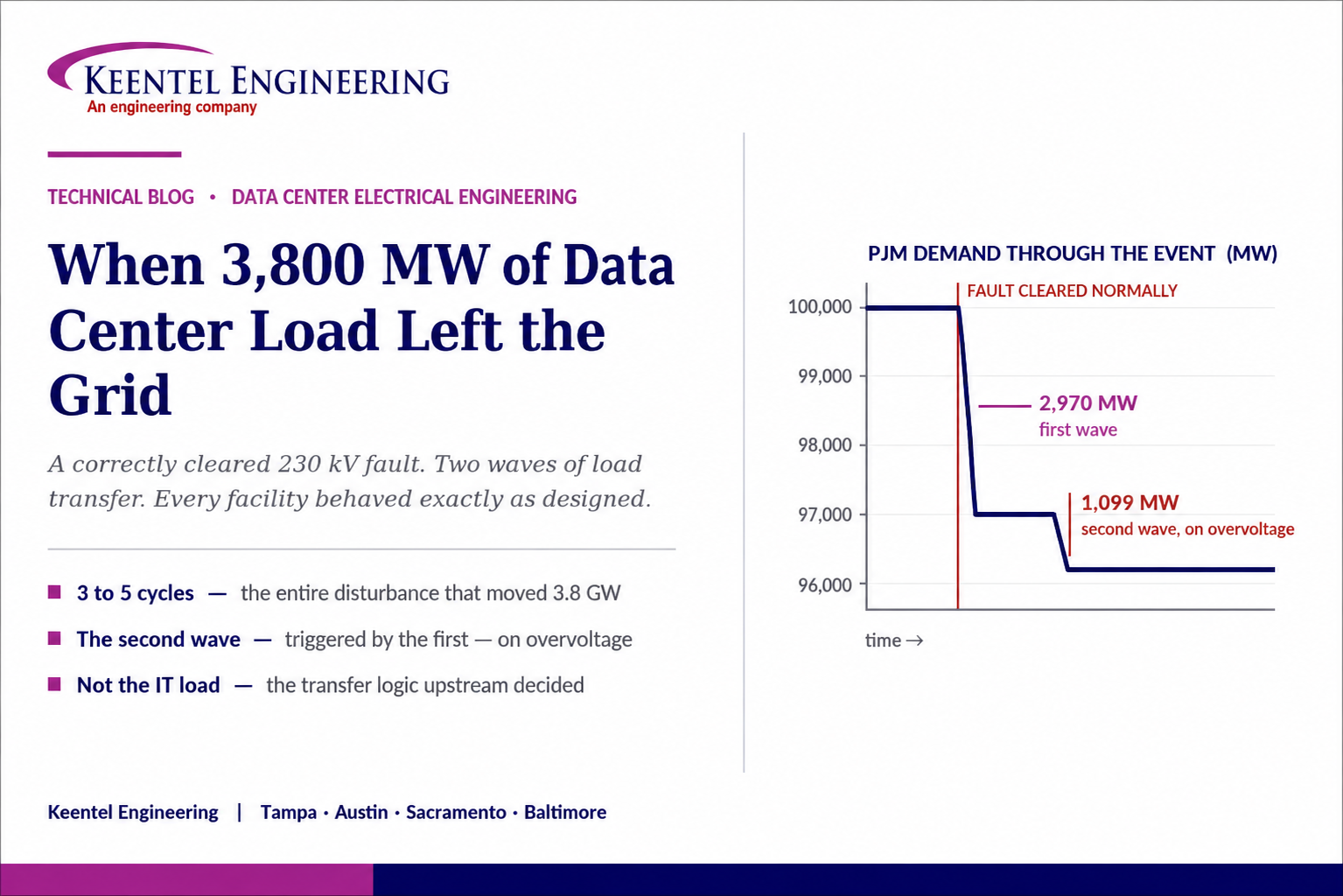
On the morning of 22 July 2026, a mechanical failure took a 230 kV line in Northern Virginia out of service. The protection system did its job: the fault was detected and cleared normally. Nothing on the transmission system failed. Within moments, roughly 3,800 MW of data center load disconnected from the grid and transferred to on-site backup generation — the largest such event in the history of the PJM footprint.
The load did not lose power. From inside those facilities, the systems performed exactly as designed: a disturbance was detected, the facility left the utility, engines started, and the IT load never noticed. From outside, several gigawatts of demand vanished in an instant and the balancing authority had to absorb the consequences.
Two details make this event more instructive than its headline number. First, it happened in two waves. The initial transfer of roughly 2,970 MW raised system voltage, and that voltage rise triggered a second group of facilities totalling roughly 1,099 MW to transfer as well. The event propagated through the grid conditions it created — the load-side analogue of a cascading trip. Second, this was not the first time. Comparable events in the same zone moved on the order of 1,500 MW each in 2024 and again in 2025. The magnitude is growing with the load.
The regulatory response has already begun. In July 2026 the Federal Energy Regulatory Commission directed NERC to develop mandatory reliability standards for computational loads, including glossary definitions and registration criteria, on a fixed filing deadline at the end of 2026, with a further work plan due in early 2027. Ride-through performance requirements are expected in the following tranche. PJM, meanwhile, is evaluating interconnection reliability requirements for large loads through its planning stakeholder process, on the reasoning that these requirements need to exist before the load arrives.
For anyone designing, building, financing, or operating a large computational load, the consequence is direct: the voltage and frequency sensitivity of the electrical system — today an internal design preference set largely by vendor defaults — is becoming a regulated performance obligation. This paper explains the mechanism, identifies where the sensitivity actually resides inside a facility, and sets out what to change in design, specification, and commissioning.
The sentence that reframes the problem
Every individual facility behaved correctly by its own design criteria. The aggregate behaviour was a reliability event.
That is the signature of a design standard optimised at the facility level and never evaluated at the system level — and it is precisely the situation the generation side of the industry was in a decade ago with inverter-based resources.
2. What Happened
The publicly reported sequence, as presented by the transmission owner and the balancing authority to their operating committee, runs as follows.
- Shortly before 8:00 a.m. local time, a mechanical failure caused a 230 kV line in Northern Virginia to be removed from service automatically.
- The fault was cleared correctly by the transmission protection system. No protection misoperation has been reported.
- Data centers in the affected zone began disconnecting from the utility and transferring to on-site backup generation. The first wave amounted to approximately 2,970 MW.
- The loss of that load caused system voltage to rise. In response to the elevated voltage, a further approximately 1,099 MW of computational load transferred to backup generation.
- Total demand on the balancing authority footprint fell by roughly 3,800 MW, from just under 100,000 MW to approximately 96,200 MW.
- Operators dispatched generation down to restore the balance and dispatched reactive resources to bring voltage back within limits. The area control error limit was recovered in about nine minutes, well inside the applicable reliability standard window.
No reliability standard was violated and no customer outside the affected facilities lost service. The system absorbed the event. That outcome should not be read as reassurance: it was absorbed because PJM is a very large balancing authority with substantial regulating capability, and because the event happened at a moment when that capability was available.
3. Why a Correctly Cleared Fault Removed 3,800 MW
The chain from a transmission fault to a multi-gigawatt load transfer is short, and every link in it is a design decision made inside a building.
3.1 A Fault Is a Regional Voltage Event
When a fault occurs on a transmission line, voltage collapses at the fault point and is depressed across a wide surrounding area for as long as the fault persists. The depth of the depression at any given bus depends on electrical distance from the fault, not physical distance. A single 230 kV fault produces a measurable voltage sag across a metropolitan-scale area, which is why a fault on one line can be seen simultaneously by dozens of unrelated facilities.
Transmission protection is fast. A normally cleared transmission fault typically lasts on the order of three to five cycles — roughly 50 to 80 milliseconds — after which voltage recovers. That is the entire duration of the disturbance that removed 3,800 MW of load.
3.2 Information Technology Equipment Is Not the Sensitive Part
The industry-standard tolerance envelopes for information technology equipment are considerably more forgiving than a three-to-five-cycle sag. Server power supplies are designed to tolerate a complete loss of input for a period comparable to a full cycle and a substantial voltage reduction for far longer. Semiconductor manufacturing equipment, which is the most sag-sensitive load class in wide industrial use, is qualified against an envelope that is still more tolerant than the disturbance in question.
The IT load, in other words, would very likely have ridden through the event untroubled. Something upstream of it decided otherwise.
3.3 The Decision Is Made by the Transfer Logic
Between the utility service and the servers sits a chain of devices that each independently evaluate source quality and each have the authority to act: medium-voltage protection at the customer substation, automatic transfer switches, uninterruptible power supply input acceptance logic, static transfer switches, and the generator start and sequencing controls. Each of these has a voltage window, a frequency window, and a time delay, and each is typically set at or near its vendor default.
Those defaults are conservative by design, because the vendor is protecting its equipment and the owner’s stated priority is availability. A device configured to leave the utility on a ten percent deviation detected within a handful of milliseconds will act on a transmission fault every time, whether or not the load behind it needed protecting.
The result is a facility whose effective ride-through capability is set not by engineering analysis of the disturbance environment, but by whichever device in the chain has the tightest acceptance window and the shortest delay.
4. The Cascade: Why the Second Wave Was Different
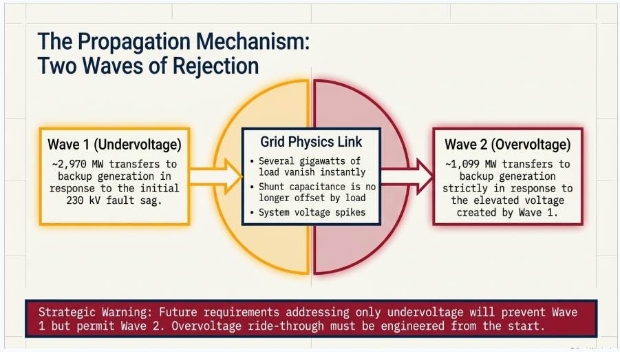
The first wave was an undervoltage response. The second was not — it was an overvoltage response, and it was caused by the first wave.
Removing several gigawatts of load from a transmission network in an instant has two immediate effects on voltage. The reactive power balance shifts: transmission lines and cables generate reactive power through their shunt capacitance, and under normal loading that generation is partly offset by the reactive consumption of the load and the series reactance of the network. Take the load away and the reactive surplus appears as a voltage rise. At the same time, the series voltage drop along the loaded circuits disappears, so the voltage profile lifts across the affected area.
That elevated voltage was then seen by a second population of facilities whose protection settings monitor for abnormal voltage in both directions. Those facilities did what they were configured to do and left as well.
Why this matters more than the total
A single large load rejection is a manageable event for a large balancing authority. A load rejection that changes system conditions enough to trigger further load rejection is a propagation mechanism.
Any future requirement that addresses only undervoltage ride-through would have prevented the first wave and permitted the second. Overvoltage ride-through belongs in the requirement, and in the facility design, from the start.
5. What the Grid Experienced
5.1 Frequency
Load and generation must balance instantaneously. Removing roughly 3,800 MW of load from a system carrying about 100,000 MW leaves an equivalent surplus of generation, and the surplus accelerates the synchronous machines still connected. System frequency rises above nominal until governor response and the operator’s dispatch bring generation back down to match.
The proportion matters. Just under four percent of system demand disappearing in a step is a substantial disturbance for the frequency response of any interconnection. It was accommodated here because the balancing authority is large and the resources were available.
5.2 Voltage
The voltage rise described in Section 4 required operator action to correct, through dispatch of reactive resources to absorb the surplus. Sustained overvoltage is not a cosmetic problem: it stresses insulation, saturates transformers, and can drive further equipment trips — which is exactly what it did.
5.3 Area Control Error and the Recovery
Area control error measures the mismatch between what a balancing authority is producing and what it should be producing given its load and its scheduled interchange. The event pushed it well outside its normal band, and it was recovered in roughly nine minutes against a standard allowing thirty. That is a good operational outcome, and it is worth noting what produced it: available regulating capability and rapid operator action, not any inherent property of the disturbance.
6. Where the Sensitivity Actually Lives
An owner asking "why did my facility leave the grid?" needs a device-level answer. The following is the inventory that a ride-through assessment should work through.
| Device or system | What it senses and decides | Typical issue |
|---|---|---|
| Customer substation protection | Undervoltage and overvoltage elements, and any transfer or load-shedding scheme at the main-tie-main or ring bus | Undervoltage elements set for equipment protection rather than coordinated with the expected transmission sag envelope; overvoltage elements often unexamined |
| Automatic transfer switches | Source voltage and frequency against dropout thresholds with a time delay before transfer | Dropout thresholds and delays left at defaults; delay short enough to act during a normally cleared transmission fault |
| Generator start and sequencing controls | Whether to issue an engine start signal, and whether starting implies transferring | Start and transfer treated as one action, so any start signal removes the facility from the utility; long retransfer delays keep it off afterwards |
| UPS input acceptance logic | Whether the incoming source is within the window the UPS will accept before going to battery or bypass | Acceptance window materially tighter than the IT load’s own tolerance; the UPS abandons a source the load could have used |
| Static transfer switches | Source quality at the distribution level and which of two sources to select | Transfer criteria uncoordinated with the UPS and ATS above them, producing sequential rather than coordinated behaviour |
| Mechanical plant drives and controls | DC bus voltage, phase loss, and control power quality at chillers, pumps, and air handling units | Drives trip on sags that the electrical system rode through; restart sequencing then dominates recovery |
| Building and electrical monitoring systems | Alarm thresholds and any automated action tied to them | Automated responses to alarms that were intended as indications |
| On-site generation and storage controls | Behaviour of engines, converters, and storage during and after the disturbance | Islanded operation with no capability or intention to support the grid; no defined behaviour for a disturbance that does not require transfer |
7. The Mechanical Plant Is the Forgotten Half
Ride-through discussions concentrate on the critical power path because that is where the IT load lives. The mechanical plant is frequently more sag-sensitive than the electrical system serving the white space, and it is not protected by the UPS.
Variable-frequency drives on chilled water pumps, condenser water pumps, cooling tower fans, and air handling units respond to a voltage sag by losing DC bus voltage and tripping on undervoltage, unless they are specified with ride-through capability and configured to use it. Chiller control systems and their safeties are similarly susceptible. A facility whose electrical system rode through a sag flawlessly but whose chilled water plant tripped is a facility now running on thermal ride-through with an unplanned restart sequence in front of it.
This has two consequences worth stating plainly. First, an owner evaluating ride-through only on the electrical side has assessed half the facility. Second, the mechanical restart behaviour is itself a grid event: simultaneous restart of large motor loads across a campus produces an inrush and a reactive demand that arrives while the system is still recovering.
8. Why Facilities Are Set This Way
It would be easy to characterise this as carelessness. It is not. It is a rational response to the incentives the industry has placed on data center operators, and understanding that is necessary to changing the outcome.
- The contractual and commercial consequence of an IT load interruption is severe and immediate. The consequence of an unnecessary generator run is fuel, maintenance hours, and an emissions entry. Faced with that asymmetry, transferring early is the defensible choice for a facility operator.
- Availability certification and design frameworks reward demonstrated independence from the utility. Nothing in the traditional data center design canon asks how the facility behaves toward the grid.
- Vendor default settings are chosen to protect equipment and to avoid nuisance complaints, not to coordinate with a transmission sag environment the vendor knows nothing about.
- The disturbance environment is invisible at design time unless someone studies it. Very few facility designs include an assessment of the voltage sag exposure at the point of service.
- Nobody has been accountable for the aggregate. Each facility is a customer, not a registered entity, and no party has been responsible for the behaviour of the population.
That last point is precisely what the regulatory response is about to change.
9. The Industry Already Solved This Once
The generation side of the industry spent the past decade working through an identical problem, and the parallel is exact enough to be predictive.
Inverter-based resources were commissioned with protection and control settings chosen by manufacturers to protect converters. Those settings caused large numbers of resources to disconnect, or to cease injecting current, during faults that transmission protection cleared normally. Successive disturbance investigations documented the same pattern each time: correctly cleared fault, widespread and unnecessary resource loss, no equipment damage, and settings that were defensible from a single manufacturer’s perspective and indefensible from the system’s.
The response progressed through recognisable stages. Post-event analysis identified the mechanism. Voluntary guidelines were issued and partially adopted. An interconnection performance standard defined the required behaviour in engineering terms. Mandatory reliability standards then made ride-through performance, and the disturbance monitoring needed to demonstrate it, enforceable obligations with defined effective dates.
The load side is now at the second stage of that same sequence, moving quickly toward the fourth. Owners who treat the current period as a window to get ahead of the requirement will find it considerably cheaper than those who wait for the standard and then retrofit.
The most useful lesson from the generation experience
The expensive part was never the requirement itself. It was discovering, after commissioning, that installed equipment could not meet it — and that the remedy was firmware, replacement, or an exemption request.
Settings are cheap to change during design and expensive to change afterwards. Equipment capability is nearly impossible to change afterwards.
10. The Regulatory Trajectory
The direction and the dates are now largely established. What is not yet established is the technical content of the requirements, which is exactly why the current period matters for anyone with a project in design.
| Development | Substance | Consequence for owners |
|---|---|---|
| FERC order directing NERC action, July 2026 | Directs development of mandatory reliability standards addressing integration of computational loads into the bulk power system, with a fixed filing deadline rather than voluntary timelines | The question is no longer whether large computational loads become subject to mandatory standards, only what the standards require |
| Glossary and definition work | Formal definition of computational load and of the entities that own and operate it | Determines which facilities are captured and at what threshold |
| Rules of Procedure and registration criteria | Revisions to bring computational load entities into the registration framework | Facilities that have always been customers may become registered entities with compliance obligations and enforcement exposure |
| First tranche of standards, due end of 2026 | Near-term measures addressing the most immediate reliability risks associated with large computational load integration | Establishes the initial obligations; ride-through performance is expected in the following tranche rather than this one |
| Further work plan, early 2027 | Plan for the additional standards, with ride-through performance requirements anticipated in that phase | The technical requirement that most affects facility electrical design is the one still being written — and therefore still open to influence |
| Regional interconnection requirements | Transmission-level evaluation of interconnection reliability requirements for large loads, developed through the planning stakeholder process | Requirements are intended to be in place before the load connects, so they will land on projects currently in development |
11. What Changes for Owners and Developers
Three changes are worth planning for now, before the details are settled.
11.1 Behaviour Becomes a Condition of Connection
Interconnection agreements for large loads have historically addressed capacity, metering, and cost allocation. They are moving toward specifying performance: how the facility must behave during and after a system disturbance. That means voltage and frequency ride-through envelopes, requirements on the behaviour of on-site generation and storage, protection coordination expectations, and possibly restart and reconnection behaviour. Projects in development should expect these terms to appear.
11.2 Compliance Obligations Attach to Facilities That Have Never Had Them
A data center campus that becomes a registered entity acquires an apparatus that most such organisations do not currently have: applicable standards, evidence retention, disturbance data, internal controls, and audit exposure. The engineering consequence is that the facility’s electrical behaviour must be documented, tested, and demonstrable, not merely designed.
11.3 Ride-Through Becomes a Study and a Test
Demonstrating ride-through capability requires knowing the disturbance environment at the point of service, knowing the sensitivity of every device that can act, and having tested the response. None of those three is standard practice in data center delivery today. All three are ordinary practice in generation interconnection, which is where the methods will be borrowed from.
12. Designing for Ride-Through
The following controls are inexpensive at design stage and progressively more expensive afterwards.
- Characterise the disturbance environment. Perform a fault and voltage sag study of the serving transmission and distribution system to establish the depth and duration envelope the facility should expect at its point of service. Without this, every setting decision downstream is guesswork.
- Establish a facility ride-through envelope as a design requirement in the basis of design, covering both undervoltage and overvoltage, with a stated tolerance in depth and duration. Make it a number, not an aspiration.
- Inventory every device that can decide to leave the utility — substation protection, transfer switches, UPS input logic, static switches, generator controls — and set each of them against the facility envelope rather than against its own default.
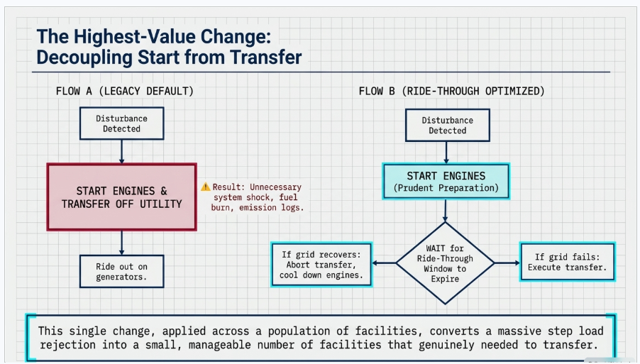
- Decouple generator starting from transfer. Starting engines on a disturbance is prudent; transferring the facility is a separate decision that should require the disturbance to persist beyond the ride-through window. This single change would have prevented a large share of the load loss in an event of this kind.
- Specify overvoltage ride-through explicitly. The second wave of this event was an overvoltage response, and overvoltage settings receive far less design attention than undervoltage.
- Use the UPS as what it is. A short transmission sag is the exact disturbance an uninterruptible power supply exists to absorb. Riding through on stored energy costs a few seconds of battery and keeps the facility on the utility.
- Specify mechanical plant ride-through. Require drives with DC bus ride-through or equivalent capability, verify chiller control power arrangements, and design the restart sequence so that the plant does not present a simultaneous inrush to a recovering system.
- Stagger and coordinate at campus scale. Where multiple halls or buildings share a point of interconnection, identical settings guarantee identical simultaneous behaviour. Diversity in transfer timing turns a step into a ramp.
- Where storage is present, use it. A facility with battery storage on the medium-voltage bus has the means to hold through a disturbance without transferring, provided the control scheme is designed for that purpose rather than only for peak shaving.
- Document the settings as a controlled register, with any change to voltage or frequency sensitivity treated as a design change requiring re-analysis rather than as a commissioning adjustment.
13. Proving It
A ride-through claim that has not been tested is a specification, not a capability. The verification regime borrows directly from established commissioning practice.
- Verify the settings actually loaded in every device against the design envelope, device by device, and record them. Settings drift during commissioning, and a vendor technician resolving a nuisance alarm can undo the entire design intent in one afternoon.
- Test the response to representative disturbances rather than inferring it. Sag testing equipment exists and is routinely used in industrial process facilities for exactly this purpose; the same approach applies to the transfer and control chain in a data center.
- Include disturbance response in integrated systems testing. The scenario matrix should contain a short sag that the facility is required to ride through without transferring, alongside the deeper and longer disturbances that require transfer.
- Instrument the point of service. Power quality recording at the utility interface, capturing sub-cycle events, is the only way to establish what the facility actually saw and how it actually responded. It is also the evidence that any future compliance obligation will require.
- Re-test after modification. Every phase of build-out, every equipment replacement, and every settings change alters the aggregate behaviour of the campus.
14. Reading the Event Correctly
Coverage of events like this tends toward two errors, and both should be avoided in any serious engineering discussion.
The facilities did not malfunction
Every system involved appears to have operated as designed. The transmission protection cleared the fault correctly. The transfer schemes detected an abnormal condition and acted. The engines started. The IT load was maintained. Describing this as equipment failure misdiagnoses it, and a misdiagnosis leads to the wrong remedy. The problem is a design criterion, applied consistently across a large population, that optimises one objective and is silent on another.
The grid did not nearly collapse
The system absorbed the event without violating a reliability standard and without customer impact. Sensational framing is unhelpful. The correct concern is trajectory, not this instance: comparable events in the same area have grown from roughly 1,500 MW to roughly 3,800 MW in two years, load in the region continues to grow rapidly, and the mechanism that produced the second wave is a propagation mechanism. A disturbance of this class occurring at a moment of tighter regulating capability is a materially different event.
And a third point, for owners
The facility that transfers unnecessarily is not only creating a system problem. It is consuming generator starts, running engines, burning fuel, incurring maintenance and emissions, and taking on the real reliability risk that a start attempt fails. Ride-through is not purely a public-good obligation imposed from outside; a facility that stays on a healthy utility source through a four-cycle sag is a facility that has avoided a risk, not accepted one.
15. Keentel Electrical Power Engineering Services
Keentel Engineering is an electrical power systems engineering firm working across large-load interconnection, data center electrical design, and the power system studies that connect the two. The work this event calls for is the work we do.
15.1 Large Load Interconnection
- Utility service planning and large-load interconnection support: load characterisation, service capacity studies, application-stage technical packages, and coordination with the serving utility, transmission provider, and system operator.
- Point-of-interconnection engineering, substation design, and medium-voltage campus distribution design for phased developments.
- Evaluation of emerging interconnection performance requirements and their design implications, including ride-through envelopes, on-site generation and storage behaviour, and protection coordination expectations.
15.2 Power System and Power Quality Studies
- Fault and voltage sag studies establishing the disturbance environment at the point of service, and the resulting facility ride-through envelope.
- Short-circuit, protective coordination and selectivity, and arc-flash studies for the customer substation and campus distribution.
- Load flow, motor starting and restart inrush analysis, harmonic and power quality studies, and grid strength assessment.
- Electromagnetic transient modelling where converter behaviour, control interaction, or fast disturbance response must be represented at the timescales protection and transfer schemes operate on.
15.3 Data Center Electrical Design
- Distribution topology development — N+1, 2N, and block-redundant architectures — evaluated against availability, concurrent maintainability, and now grid-behaviour requirements together rather than separately.
- UPS, static switch, transfer switch, and generator plant design and settings philosophy, developed as a coordinated facility ride-through scheme rather than as independently defaulted devices.
- Storage integration for ride-through, peak management, and load flexibility, including the power quality and interconnection consequences of adding a converter to the campus.
- Grounding, bonding, and lightning protection design, and white-space power distribution.
15.4 Commissioning, Compliance, and Owner’s Engineer Support
- Ride-through assessment of existing facilities: settings inventory, sensitivity analysis against the measured or studied disturbance environment, and a prioritised remediation plan.
- Commissioning specification and test script development, including disturbance response scenarios within integrated systems testing, and power quality baseline and verification survey scoping.
- Preparation for emerging compliance obligations: evidence structure, disturbance monitoring architecture, and settings change control.
- Design review of EPC and vendor submittals, QA/QC of third-party study packages, and equipment specification including behavioural requirements rather than ratings alone.
Keentel Engineering holds a Florida Certificate of Authorization and maintains offices in Tampa, Austin, Sacramento, and Baltimore, supporting projects across the interconnections.
16. Frequently Asked Questions
A mechanical failure removed a 230 kV line in Northern Virginia from service. The transmission protection cleared the fault normally. Data centers in the affected zone then disconnected from the utility and transferred to on-site backup generation — approximately 2,970 MW in a first wave and approximately 1,099 MW in a second, for a total near 3,800 MW. It was the largest such load transfer event in the PJM footprint to date.
No. They transferred to on-site backup generation and continued operating. The IT load was maintained throughout. The disruption was to the grid, not to the facilities.
No. The fault was detected and cleared normally. That is what makes the event significant: the disturbance was the routine consequence of a correctly functioning protection system, and it should have been unremarkable for connected load.
A normally cleared transmission fault typically lasts on the order of three to five cycles — roughly 50 to 80 milliseconds. That is the duration of the event that removed nearly four gigawatts of load.
Less than most people assume, and less than the systems protecting it. Standard tolerance envelopes for information technology equipment accommodate a complete loss of input for a period comparable to one cycle, and substantial voltage reduction for far longer. The IT load would very likely have ridden through this disturbance. The decision to leave was made by devices upstream of it.
Some combination of customer substation protection, automatic transfer switches, uninterruptible power supply input acceptance logic, static transfer switches, and generator start and sequencing controls. Each has voltage and frequency windows and time delays, each is typically left near vendor defaults, and the facility’s effective ride-through is set by whichever is tightest and fastest.
The first wave caused system voltage to rise. Removing several gigawatts of load leaves a reactive surplus on a transmission network whose shunt capacitance is no longer offset by load, and the series voltage drop along the loaded circuits disappears. A second population of facilities detected the elevated voltage and transferred in response. The first wave created the condition that triggered the second.
Because it is a propagation mechanism. A single large load rejection is a manageable disturbance for a large balancing authority. A load rejection that changes system conditions enough to cause further load rejection is a different class of problem. It also means a requirement addressing only undervoltage ride-through would have prevented the first wave and permitted the second.
A generation surplus of roughly four percent of system demand, which raised frequency above nominal until governor response and dispatch corrected it, and a voltage rise requiring dispatch of reactive resources. The area control error limit was recovered in about nine minutes against a thirty-minute standard.
Not on this occasion. No reliability standard was violated and no customers outside the affected facilities were interrupted. The system absorbed it because the balancing authority is large and regulating capability was available at the time. The concern is trajectory: comparable events in the same area grew from roughly 1,500 MW to roughly 3,800 MW over two years, and the load continues to grow.
Yes. Comparable events in the same zone moved on the order of 1,500 MW each in 2024 and 2025. The mechanism is established; the magnitude is what is changing.
Because the incentives point that way. An IT load interruption has severe and immediate commercial consequences; an unnecessary generator run costs fuel and maintenance hours. Availability frameworks reward independence from the utility and say nothing about behaviour toward it. Vendor defaults are chosen to protect equipment. And until now, no party has been accountable for the aggregate behaviour of the population.
Structurally, yes. Inverter-based resources were commissioned with manufacturer settings that caused unnecessary disconnection during correctly cleared faults. The response ran from post-event analysis, to voluntary guidelines, to a performance standard defining required behaviour, to mandatory reliability standards with enforcement dates. The load side is now moving through the same sequence.
In July 2026 FERC directed NERC to develop mandatory reliability standards addressing the integration of computational loads, with a filing deadline at the end of 2026 covering initial standards, glossary definitions, and registration criteria, and a further work plan due in early 2027. Ride-through performance requirements are expected in the subsequent phase rather than the first. Regional interconnection requirements for large loads are being developed in parallel.
That is the direction. The FERC direction includes revising the registration framework to bring computational load entities into it. The engineering consequence is that facility electrical behaviour will need to be documented, tested, and demonstrable rather than simply designed.
Perform a voltage sag study at the point of service, set a facility ride-through envelope covering both undervoltage and overvoltage as a stated design requirement, and set every device that can leave the utility against that envelope rather than against its default. Decouple engine starting from transfer. Specify mechanical plant ride-through. Those four steps address most of the exposure and cost very little at design stage.
Start with a settings inventory across substation protection, transfer switches, UPS input logic, static switches, and generator controls, and compare it against the disturbance environment established by study or by measurement at the service. Most facilities find that a small number of devices govern the outcome and that several are adjustable. Instrument the point of service so that the next event produces evidence rather than speculation.
Generally the opposite. A short transmission sag is precisely the disturbance an uninterruptible power supply exists to absorb, and riding through on stored energy costs seconds of battery. The alternative — transferring — consumes generator starts, runs engines, and takes on the genuine risk that a start attempt fails. Staying on a healthy utility source through a brief sag avoids risk rather than accepting it.
Very much so, and it is the half most often missed. Variable-frequency drives on pumps, fans, and cooling equipment trip on sags that the critical power path rides through, and they are not behind the UPS. A facility whose electrical system held but whose chilled water plant tripped is on thermal ride-through with an unplanned restart in front of it — and that simultaneous restart is itself a load event for a recovering system.
Separate the decision to start engines from the decision to leave the utility. Starting on a disturbance is prudent. Transferring should require the disturbance to persist beyond a defined ride-through window. That one change, applied across a population of facilities, converts a step load rejection into a small number of facilities that genuinely needed to transfer.
References and Further Reading
The sources below were consulted in preparing this document and are provided so that readers can verify the factual account and follow developments directly. Reporting of the July 2026 event reflects preliminary findings and remains subject to revision. All links were current at the date of publication.
The July 2026 Event
- July 22, 2026 Dominion Load Transfer Event — presentation to the PJM Operating Committee, August 6, 2026 — PJM Interconnection
https://www.pjm.com/-/media/DotCom/committees-groups/committees/oc/2026/20260806/20260806-item-05---dominion-july-loss-of-load-event---presentation.pdf - PJM, Dominion Review Large Load Transfer Event — PJM Inside Lines, August 11, 2026
https://insidelines.pjm.com/pjm-dominion-review-large-load-transfer-event/ - PJM eyes data center, crypto reliability requirements after 3.8 GW of load trips offline — Utility Dive
https://www.utilitydive.com/news/pjm-nerc-data-center-crypto-reliability-standards/827653/ - PJM, Dominion Review Large Load Transfer Event — American Public Power Association
https://www.publicpower.org/periodical/article/pjm-dominion-review-large-load-transfer-event - 3.8 GW Load Drop Prompts Potential PJM Data Center Rules — Data Center Knowledge
https://www.datacenterknowledge.com/regulations/3-8-gw-load-drop-prompts-potential-pjm-rules - PJM reviewing potential changes to interconnection reliability requirements — Daily Energy Insider
https://dailyenergyinsider.com/news/53411-pjm-reviewing-potential-changes-to-interconnection-reliability-requirements/
The Regulatory Framework
The governing document is the Commission order itself: Reliability Standard(s) Pertaining to Computational Load Integration, Docket No. RD26-7-000, 196 FERC ¶ 61,031, issued July 16, 2026. The order builds on the large-load interconnection rulemaking record in Docket No. RM26-4, which followed a Department of Energy advance notice of proposed rulemaking issued in October 2025. The analyses below summarise the order and its deadlines.
- FERC Orders New Reliability Standards for Data Centers and Other Computational Loads — Willkie Farr & Gallagher
https://www.willkie.com/publications/2026/07/ferc-orders-new-reliability-standards-for-data-centers-and-other-computational-loads - FERC Directs NERC to Submit Rules Addressing Risks Associated with Integration of Computational Loads into Bulk Power System — Troutman Pepper Locke, Washington Energy Report
https://www.troutmanenergyreport.com/2026/07/ferc-directs-nerc-to-submit-rules-addressing-risks-associated-with-integration-of-computational-loads-into-bulk-power-system/ - FERC Directs NERC To File Reliability Standards That Apply To Data Centers — Sheppard Mullin
https://www.sheppard.com/insights/blogs/ferc-directs-nerc-to-file-reliability-standards-apply-data-centers - FERC Orders Mandatory NERC Reliability Standards for Data Center and Other Computational Loads — POWER Magazine, July 16, 2026
https://www.powermag.com/ferc-orders-mandatory-nerc-reliability-standards-for-data-center-and-other-computational-loads/ - FERC Directs Large Load Standards by End of 2026 — RTO Insider
https://www.rtoinsider.com/136792-ferc-directs-large-loads-standards-by-end-of-2026/
Standards and Technical References
The following are referenced by subject in the body of this document. The current published edition of each governs.
- NERC Reliability Standards — including the PRC series addressing ride-through performance and disturbance monitoring for inverter-based resources, and the MOD series addressing modelling data and model verification — North American Electric Reliability Corporation
https://www.nerc.com/pa/Stand/Pages/ReliabilityStandards.aspx - NERC 2026 State of Reliability, which identified large computational loads as a growing source of frequency and voltage instability during system disturbances — North American Electric Reliability Corporation
https://www.nerc.com/pa/RAPA/PA/Pages/default.aspx - IEEE Std 2800, Standard for Interconnection and Interoperability of Inverter-Based Resources Interconnecting with Associated Transmission Electric Power Systems — the generation-side performance standard discussed as precedent in Section 9 — IEEE Standards Association
https://standards.ieee.org/ieee/2800/10453/ - ITI (CBEMA) Curve Application Note — the voltage tolerance envelope for information technology equipment referenced in Section 3 — Information Technology Industry Council
https://www.itic.org/ - SEMI F47, Specification for Semiconductor Processing Equipment Voltage Sag Immunity — the industrial sag immunity benchmark referenced in Section 3 — SEMI
https://www.semi.org/en/standards - IEEE Std 1159, Recommended Practice for Monitoring Electric Power Quality, and IEEE Std 1668, Recommended Practice for Voltage Sag and Short Interruption Ride-Through Testing for End-Use Electrical Equipment — methods relevant to the assessment and testing described in Sections 12 and 13 — IEEE Standards Association
https://standards.ieee.org/
Notice and Disclaimer
This document is original technical content prepared by Keentel Engineering LLC for general professional information. It is not project-specific engineering advice and does not constitute a design, a study, a settings recommendation, or a compliance determination for any facility.
Descriptions of the July 2026 event are based on preliminary findings reported publicly by the transmission owner and the balancing authority as of the date of publication, as listed in the References section. Preliminary findings are subject to revision as investigation continues, and this document should not be treated as an authoritative account of the event, its causes, or the conduct of any party involved. No statement here characterises the design, settings, or performance of any particular facility, owner, or operator.
Regulatory developments described here were in progress at the date of publication. Deadlines, definitions, registration criteria, and the technical content of any resulting requirements are subject to the standards development process and to the decisions of the applicable authorities. The governing documents are those published by the relevant regulator, standards body, system operator, and utility, and should be verified directly for any project decision.
Keentel Engineering LLC is an independent engineering consultancy. Reference to any standard, regulator, system operator, utility, industry organisation, or equipment category in this document does not imply affiliation with, endorsement by, or sponsorship from any such organisation.

About the Author:
Sandip "Sonny" R. Patel, P.E.
IEEE Senior Member · Founder & CEO, Keentel Engineering
In 1995, Sonny Patel earned his Electrical Engineering degree from the University of Illinois. But degrees don't build legacies — action does.
For three decades, he has worked the power industry from every side of the table: 16 years as a utility engineer at Exelon/Commonwealth Edison; generation leadership across hydroelectric, industrial steam turbine, and a 9 GW renewable fleet; NERC Regional Entity Senior Compliance Engineer and Audit Team Lead, auditing some of the nation's largest utilities; and testing and commissioning lead on equipment up to 765 kV — the very top of the North American grid.Utility. Generator. Regulator. Consultant. Few engineers have seen all four seats. Fewer still have sat in them.
His experience spans nuclear, hydro, conventional generation, renewables, oil and gas, mining — and today's data centers, where he is authoring a three-book series on data center design. He is a Licensed Professional Engineer in six states and a Licensed Electrical Contractor in Florida (Unlimited EC) — he doesn't just design the work; he's qualified to stand behind its execution.Today, as Founder and CEO of Keentel Engineering, Sonny leads a nationwide team of engineers delivering substation design, power system studies, NERC compliance, and commissioning — done right, coast to coast.Three decades. Every side of the table. One standard: accountable engineering.
Services

Let's Discuss Your Project
Let's book a call to discuss your electrical engineering project that we can help you with.
About the Author:
Sandip "Sonny" R. Patel, P.E.
IEEE Senior Member · Founder & CEO, Keentel Engineering
In 1995, Sonny Patel earned his Electrical Engineering degree from the University of Illinois. But degrees don't build legacies — action does.
For three decades, he has worked the power industry from every side of the table: 16 years as a utility engineer at Exelon/Commonwealth Edison; generation leadership across hydroelectric, industrial steam turbine, and a 9 GW renewable fleet; NERC Regional Entity Senior Compliance Engineer and Audit Team Lead, auditing some of the nation's largest utilities; and testing and commissioning lead on equipment up to 765 kV — the very top of the North American grid.
Utility. Generator. Regulator. Consultant. Few engineers have seen all four seats. Fewer still have sat in them.
His experience spans nuclear, hydro, conventional generation, renewables, oil and gas, mining — and today's data centers, where he is authoring a three-book series on data center design. He is a Licensed Professional Engineer in six states and a Licensed Electrical Contractor in Florida (Unlimited EC) — he doesn't just design the work; he's qualified to stand behind its execution.
Today, as Founder and CEO of Keentel Engineering, Sonny leads a nationwide team of engineers delivering substation design, power system studies, NERC compliance, and commissioning — done right, coast to coast.Three decades. Every side of the table. One standard: accountable engineering.
Leave a Comment
Thank you for contacting us.
We will get back to you as soon as possible.
We will get back to you as soon as possible.
Oops, there was an error sending your message.
Please try again later.
Please try again later.
Related Posts

By SANDIP R PATEL
•
October 13, 2026
Plan data center capacity with land screening, MW-per-acre estimates, grid power availability and interconnection feasibility studies from Keentel Engineering.

By SANDIP R PATEL
•
October 11, 2026
Learn which fault produces the highest current at a bus, why SLG faults can exceed three-phase faults, and how symmetrical components determine fault duty.

By SANDIP R PATEL
•
October 11, 2026
Learn why zero-sequence current pulsates in the dq0 frame, how Park's transformation works, and how inverter controls handle unbalance and ground faults.

By SANDIP R PATEL
•
October 11, 2026
Explore grid inertia, RoCoF and frequency response, with swing equation calculations, frequency nadir analysis and US power system simulation examples.

By SANDIP R PATEL
•
October 11, 2026
Learn transient stability analysis, swing equation, equal-area criterion and critical clearing time with a 345 kV worked example and NERC TPL-001 guidance.

By SANDIP R PATEL
•
October 11, 2026
Learn why inverter controls become unstable in weak grids, how PLL bandwidth and SCR affect stability, and how PSCAD EMT studies identify and mitigate oscillations.

By SANDIP R PATEL
•
October 11, 2026
Learn how STATCOMs improve voltage stability and prevent FIDVR. Explore reactive power sizing, delayed fault clearing, NERC criteria and 138 kV simulation results.

By SANDIP R PATEL
•
October 10, 2026
Learn BESS DC sizing with power, energy, current and C-rate calculations, battery losses, degradation and a 100 MW/400 MWh utility-scale example.

By SANDIP R PATEL
•
October 10, 2026
Learn how BESS ROI is calculated using peak shaving, energy arbitrage, power quality and battery storage economics, with a practical 5 MW/10 MWh example.





