
A Coordinated Electric System Interconnection Review—the utility’s deep-dive on technical and cost impacts of your project.
Challenge: Frequent false tripping using conventional electromechanical relays
Solution: SEL-487E integration with multi-terminal differential protection and dynamic inrush restraint
Result: 90% reduction in false trips, saving over $250,000 in downtime
The three operating regions you have to design to
| Device | Output vs voltage | Response | Best suited to | Main limitations |
|---|---|---|---|---|
| Mechanically switched capacitor or reactor | Proportional to voltage squared | Seconds; discrete steps; limited switching operations per day | Steady-state reactive supply, voltage profile, loss reduction | No dynamic capability; step voltage change on switching; capability collapses when most needed |
| Static var compensator | Capacitive branches proportional to voltage squared | A few cycles; continuously controllable | Continuous control where cost matters and deep voltage support is not the driver | Square-law capability loss; harmonic filters are part of the plant and interact with the network |
| STATCOM | Approximately proportional to voltage — constant current capability | One to two cycles closed loop; converter response faster still | Voltage stability margin, weak interconnections, fast disturbance recovery, flicker and unbalance compensation | Higher capital cost; converter losses; adds a converter and its control dynamics to the network |
| Synchronous condenser | Governed by machine capability and excitation | Excitation response in the hundreds of milliseconds; inherent inertial response instantaneous | System strength and inertia, short-circuit contribution, black start support | Rotating plant with maintenance and losses; slower controlled response than a converter |
| STATCOM with energy storage | Reactive as a STATCOM, plus real power within the storage rating | As STATCOM for reactive; real power limited by storage | Where a real power deficiency is part of the problem | Cost and complexity of the storage; different failure and maintenance profile |
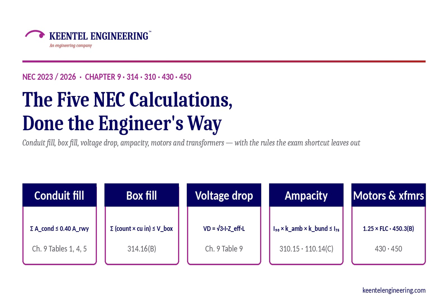
The Five NEC Calculations, Done the Engineer's Way
September 7, 2026 | Blog
Conduit and raceway fill, box and pull-box fill, voltage drop, conductor ampacity, and motor and transformer circuit sizing — the exam shortcuts, the Code rules the shortcuts leave out, and the worked examples an engineer actually needs on a design
Executive Summary
Five calculations account for most of the arithmetic in electrical design below 1,000 volts: how many conductors fit in a raceway, how large a box must be, how much voltage a run loses, how much current a conductor can carry after it has been derated, and how motor and transformer circuits are protected. Every licensing exam tests them and every exam-prep publisher condenses them to a page apiece. The condensed versions are correct as far as they go. They are also incomplete in ways that matter the moment the calculation leaves the exam hall and enters a stamped drawing.
This guide restates each calculation at engineering depth. For conduit fill it adds the nipple allowance, the 0.8 rounding rule, the treatment of multiconductor cable, and the jam ratio. For box fill it adds the equipment-grounding-conductor allowance as revised in 2020, the double allowance for wide device yokes, and the pull-box rules of 314.28 that the exam sheets omit entirely. For voltage drop it shows why the familiar K-method underestimates the drop on any feeder with reactance and power factor, and how to use Chapter 9 Table 9 instead. For ampacity it adds the 110.14(C) termination rule as the Code actually states it, the neutral-counting rules, the rooftop adder, and the interaction with 240.4. For motors it restores the instantaneous-trip breaker, the next-size-up exception, the overload rules, the multi-motor feeder, and the disconnect. For transformers it adds the full 450.3(B) table and the secondary-conductor rules of 240.21(C), without which a primary-only calculation produces an unprotected conductor.
Each section carries a worked example built for design rather than for a 90-second exam question. Section numbers are cited to the 2023 edition of NFPA 70; the 2026 edition relocated the load-calculation article from 220 to 120 but left the sections used here in place, and the guide notes where an edition-specific check is warranted. Section 7 collects the places where circulating exam material would lead a designer into a plan-review comment, and Section 8 describes how Keentel Engineering applies these calculations in design and peer review.
A note on "exam values" versus design values
Exam-prep tables are often labeled "illustrative" and rounded. Every number in this guide is taken from the NEC tables at the cited location and is the number a designer would use, but the reader is still responsible for confirming each value against the edition and amendments adopted by the authority having jurisdiction before relying on it.
1. Conduit and Raceway Fill (Chapter 9)
Chapter 9 Table 1 sets the maximum percentage of a raceway's internal cross-section that conductors may occupy: 53 percent for one conductor, 31 percent for two, and 40 percent for three or more. The percentages exist for two reasons: heat, because a tightly packed raceway cannot shed it, and pulling, because a fill above 40 percent raises sidewall pressure and the risk of insulation damage during installation. The fill counts every conductor in the raceway, including the equipment grounding conductor and any conductor that is spliced through.
Chapter 9 Table 4 gives, for every raceway type and trade size, the internal diameter, the total internal area, and the area at 53, 31, 40, and 60 percent, so the multiplication is already done. Table 5 gives the approximate diameter and area of each insulated conductor by size and insulation type; Table 5A does the same for compact stranded conductors, and Table 8 gives bare conductor dimensions. Informative Annex C tabulates the maximum number of conductors of one size and type in each raceway, and is the fastest route whenever all conductors are identical.
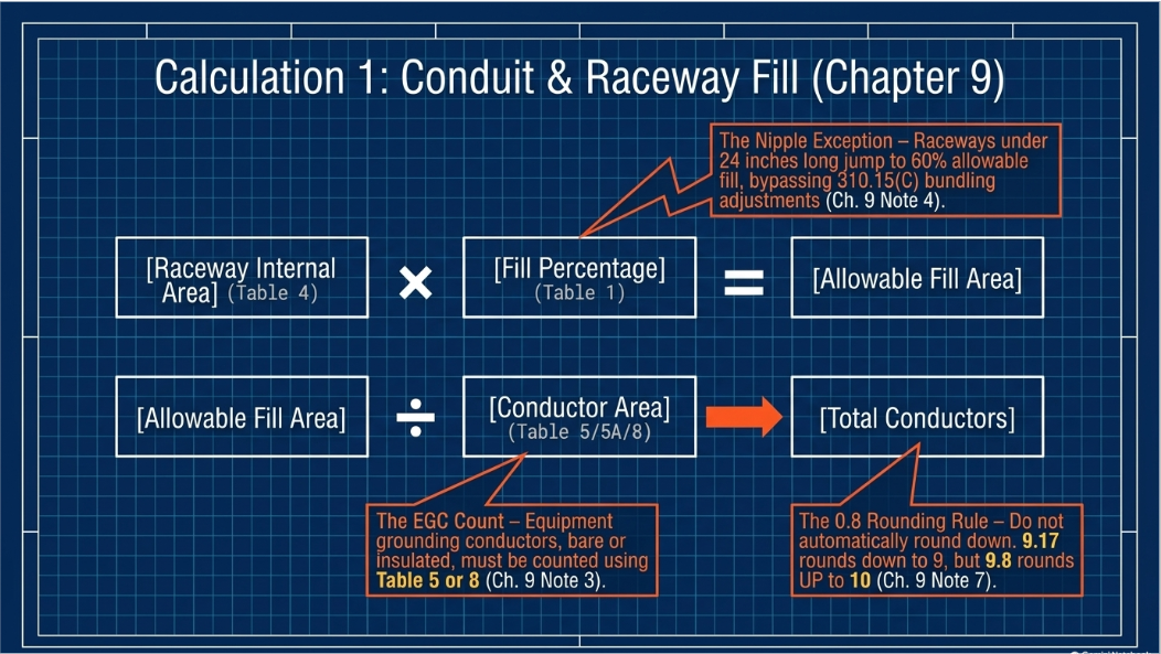
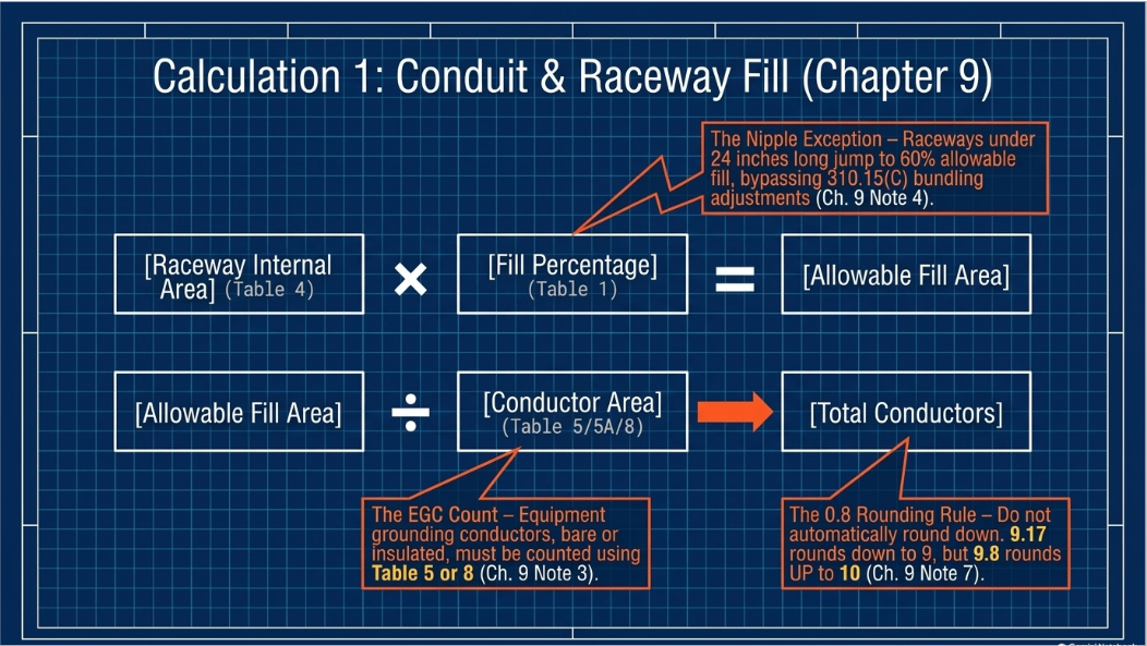
| Rule | Where | What it says |
|---|---|---|
| Fill percentages | Ch. 9 Table 1 | 1 conductor 53%; 2 conductors 31%; over 2 conductors 40%. |
| Nipples | Ch. 9 Note 4 | A raceway not over 24 in. long between boxes or enclosures may be filled to 60%, and the 310.15(C) adjustment factors do not apply to it. |
| Rounding | Ch. 9 Note 7 | Where a calculation of the number of same-size conductors yields a decimal of 0.8 or larger, the next higher whole number is permitted. 9.1 rounds down to 9; 9.8 rounds up to 10. |
| Multiconductor cable | Ch. 9 Note 9 | A multiconductor cable, or a flexible cord, is treated as a single conductor of its overall diameter; for an elliptical cable the major diameter is used as a circle. |
| Equipment grounding conductors | Ch. 9 Note 3 | EGCs and bonding conductors, insulated or bare, are counted in the fill using Table 5 or Table 8. |
| Jam ratio | Ch. 9 Table 1, Informational Note 2 | When three conductors are pulled together, a ratio of raceway inside diameter to conductor outside diameter between about 2.8 and 3.2 invites jamming; the fill percentage does not protect against it. |
Worked example 1A — identical conductors: 12 AWG THHN in ½-inch EMT
½-inch EMT internal area (Ch. 9 Table 4)
0.304 in²
Allowable fill at 40% (Table 4, "over 2 wires" column)
0.122 in²
12 AWG THHN area (Ch. 9 Table 5)
0.0133 in²
0.122 ÷ 0.0133
9.17 → 9 conductors
Cross-check: Annex C Table C.1, EMT ½-inch, THHN 12 AWG
9
If the run were a 20-inch nipple: 0.304 × 0.60 = 0.182 ÷ 0.0133 = 13.7 → 13 conductors, with no bundling adjustment.
Worked example 1B — mixed sizes: 480 V feeder in EMT
Conductors: 3 × 500 kcmil THHN phase, 1 × 250 kcmil THHN neutral, 1 × 1/0 AWG THHN equipment grounding conductor
500 kcmil THHN area (Table 5) 0.7073 in² × 3
2.1219 in²
250 kcmil THHN area (Table 5)
0.3970 in²
1/0 AWG THHN area (Table 5)
0.1855 in²
Total conductor area
2.7044 in²
2½-inch EMT at 40% (Table 4)
2.343 in² — insufficient
3-inch EMT at 40% (Table 4)
3.538 in² — acceptable, 76% of allowable
Minimum raceway
3-inch EMT
Jam check on the three 500 kcmil: EMT 3-inch ID 3.356 in ÷ 500 kcmil THHN OD 0.949 in = 3.54, outside the 2.8–3.2 jam band.
Two design considerations sit outside the fill calculation but decide whether the raceway is buildable. First, pulling tension and sidewall pressure on long runs with multiple bends are not addressed by Chapter 9 at all; the conductor manufacturer's limits, typically 0.008 lb per circular mil for copper and a sidewall pressure limit in the region of 500 lb/ft for THHN, govern, and a 40 percent fill in a 3-inch raceway through four 90-degree bends can exceed them. Second, the fill calculation counts conductors at their nominal Table 5 dimensions; a compact-stranded or oversized-insulation product changes the arithmetic and the manufacturer's data should be used when it differs from Table 5.
2. Box Fill and Pull-Box Sizing (Article 314)
Section 314.16 governs boxes containing conductors 6 AWG and smaller. The volume of the box, from Table 314.16(A) for standard metal boxes or from the marked volume for others, must be at least the sum of the volume allowances for everything in it. Table 314.16(B) gives the allowance per conductor: 14 AWG 2.00 in³, 12 AWG 2.25 in³, 10 AWG 2.50 in³, 8 AWG 3.00 in³, 6 AWG 5.00 in³. The counting rules in 314.16(B)(1) through (B)(5) are where the errors happen.
| Item | Allowance | Detail that is frequently missed |
|---|---|---|
| Conductors | One per conductor that originates outside the box and terminates or is spliced inside; one per conductor that passes through unbroken | A looped conductor at least twice the minimum free length of 300.14 (twice 6 in.) counts as two. Pigtails and jumpers that originate and end inside the box count zero. A conductor that passes through with no more than 12 in. of it in the box counts one. |
| Cable clamps | One allowance total, based on the largest conductor present | Only for clamps internal to the box; external clamps and connectors count zero. |
| Support fittings | One allowance per fixture stud or hickey, based on the largest conductor present | — |
| Devices and equipment | Two allowances per yoke or strap, based on the largest conductor connected to the device | A device or utilization equipment wider than 50 mm (2 in.) takes two allowances for each gang it requires. |
| Equipment grounding conductors | One allowance for all EGCs together, based on the largest EGC in the box | Since the 2020 edition the allowance is based on the largest equipment grounding conductor, not the largest conductor in the box, and one additional allowance is required for each additional set of four or fewer isolated (insulated) EGCs. |
Worked example 2A — device box with three 12-2 with ground cables
Three NM cables, 12-2 with ground, entering; one duplex receptacle; internal cable clamps
Circuit conductors: 3 cables × 2 = 6 × 2.25 in³
13.50 in³
Internal clamps: 1 allowance × 2.25 in³
2.25 in³
Receptacle yoke: 2 allowances × 2.25 in³
4.50 in³
Equipment grounding conductors (all 12 AWG): 1 allowance × 2.25 in³
2.25 in³
Minimum box volume
22.50 in³
A 4 × 1½ in. square box with a single-gang plaster ring (21.0 + ring marking) or a 4 × 2⅛ in. square box (30.3 in³) satisfies it; a 3 × 2 × 3½ in. device box (18.0 in³) does not.
2.1 Pull and junction boxes for conductors 4 AWG and larger (314.28)
Exam sheets stop at 314.16, but the box that a designer most often sizes is the pull box on a feeder, and that is governed by 314.28, which applies to raceways containing conductors 4 AWG and larger. For a straight pull, the length of the box must be at least eight times the trade size of the largest raceway. For an angle or U pull, or where splices are made, the distance from each raceway entry to the opposite wall must be at least six times the trade size of the largest raceway in that row, plus the sum of the trade sizes of the other raceways in the same row on the same wall. In addition, the distance between raceway entries enclosing the same conductor must be at least six times the trade size of the larger raceway. Where the box is smaller than these dimensions, 314.28(A)(3) permits it only if it is marked with the maximum number and size of conductors.
Worked example 2B — angle pull box, one 3-inch and one 2-inch raceway per wall
Angle pull, 3-inch raceway entering the left wall and leaving the bottom wall; a 2-inch raceway follows the same path
Left wall to right wall: 6 × 3 + 2
20 in. minimum
Top wall to bottom wall: 6 × 3 + 2
20 in. minimum
Distance between the 3-inch entries (left to bottom): 6 × 3
18 in. minimum, measured between nearest edges
If the same raceways passed straight through: 8 × 3
24 in. minimum length
Specify a 20 × 20 in. box with the 3-inch entries located so that the 18 in. edge-to-edge distance is met; depth per the raceway locknut and bushing dimensions.
3. Voltage Drop: The K Method and the Impedance Method (Chapter 9, Table 9)
The NEC does not mandate a voltage-drop limit for general branch circuits and feeders. Informational Notes at 210.19(A) and 215.2(A) recommend a maximum of 3 percent on a branch circuit or a feeder and 5 percent combined, and the notes are advisory. Mandatory limits exist for specific occupancies: 647.4(D) limits sensitive-electronic-equipment circuits to 1.5 percent branch and 2.5 percent combined, 695.7 limits the fire-pump controller to 15 percent at motor start and 5 percent at 115 percent of full-load current, and energy codes adopted alongside the NEC in many jurisdictions impose their own limits. Voltage drop is nevertheless a design constraint on nearly every project, because equipment performance, motor starting, and LED driver behavior all depend on it.
3.1 The K method
The exam formula treats the conductor as a pure resistance. For single-phase, VD = 2 × K × I × L ÷ CM; for three-phase, VD = 1.732 × K × I × L ÷ CM, where K is the resistivity in ohm-circular-mils per foot (12.9 for copper and 21.2 for aluminum at 75 °C), I is the load current, L is the one-way length in feet, and CM is the conductor area in circular mils from Chapter 9 Table 8 (14 AWG 4,110; 12 AWG 6,530; 10 AWG 10,380; 8 AWG 16,510; 6 AWG 26,240; 4 AWG 41,740; 1/0 105,600; 4/0 211,600; 500 kcmil 500,000). The method is adequate for small conductors at unity power factor, which is the exam case. It is not adequate for feeders, because it ignores conductor reactance and load power factor.
3.2 The impedance method
Chapter 9 Table 9 lists, per 1,000 feet at 75 °C, the AC resistance and the inductive reactance of each conductor size in PVC, aluminum, and steel raceways, and an effective impedance at 0.85 power factor. The line-to-neutral voltage drop is I × (R cos θ + X sin θ) × L ÷ 1,000, and the line-to-line drop for a three-phase circuit is that quantity times 1.732. For a power factor other than 0.85 the effective impedance is recalculated from R and X. Reactance depends on conductor spacing and on the raceway material; conductors in steel conduit have the highest reactance, which is why Table 9 carries three columns.
Worked example 3A — the exam case: 20 A, 120 V, 150 ft, 12 AWG copper
VD = 2 × 12.9 × 20 × 150 ÷ 6,530
11.85 V
Percent of 120 V
9.9% — far above the 3% recommendation
Minimum circular mils for 3% (3.6 V): 2 × 12.9 × 20 × 150 ÷ 3.6
21,500 CM
Next standard size at or above 21,500 CM (Table 8)
6 AWG (26,240 CM)
Drop with 6 AWG: 77,400 ÷ 26,240
2.95 V, 2.5%
Design consequence: 250.122(B) requires the equipment grounding conductor to be increased in proportion to the circular-mil increase of the ungrounded conductors. From 12 AWG (6,530) to 6 AWG (26,240) is a ratio of 4.02; the 12 AWG EGC (6,530) becomes 26,240 CM, i.e., 6 AWG.
Worked example 3B — a real feeder: 320 A, 480 V three-phase, 0.85 PF, 400 ft, 4/0 AWG copper in steel conduit
K method: 1.732 × 12.9 × 320 × 400 ÷ 211,600
13.5 V, 2.8% — appears to pass 3%
Table 9, 4/0 AWG copper, steel conduit: R = 0.063 Ω/kft, X = 0.051 Ω/kft
Effective Z at 0.85 PF: 0.063 × 0.85 + 0.051 × 0.527
0.0804 Ω/kft (Table 9 lists 0.080)
Line-to-line drop: 1.732 × 320 × 0.0804 × 0.400
17.8 V
Percent of 480 V
3.7% — fails the 3% recommendation
Same feeder in PVC conduit: R 0.062, X 0.041 → Z_eff 0.0743 → 16.5 V, 3.4%
Same feeder with 250 kcmil copper in steel: Table 9 Z_eff 0.073 → 16.2 V, 3.4%; 300 kcmil Z_eff 0.065 → 14.4 V, 3.0%
The K method under-reports this drop by about 25 percent. The difference is the reactive term, which the K method cannot see and which grows with conductor size and lagging power factor.
Three further points matter in design. The current used should be the design load, which for a continuous load is the actual current and not the 125 percent used for conductor sizing. Where the conductor operates well below 75 °C, resistance is lower than Table 9 and the drop is smaller; where a run is derated for ambient or bundling and still runs hot, the reverse. And parallel conductor sets divide the current: a 320 A feeder on two sets of 1/0 AWG has 160 A in each set, and the drop is computed on that basis
4. Conductor Ampacity and Adjustment (Article 310 and 110.14)
Section 310.14 defines ampacity as the maximum current a conductor can carry continuously without exceeding its temperature rating, and permits it to be found either from the tables of 310.15 and 310.16 through 310.21 or by engineering calculation under 310.14(B) using the Neher-McGrath method. Table 310.16 is the everyday table: not more than three current-carrying conductors in a raceway, cable, or directly buried, at 30 °C ambient, with columns for 60 °C, 75 °C, and 90 °C insulation. Everything else is an adjustment to that table.
| Adjustment | Section | Rule |
|---|---|---|
| Ambient temperature | 310.15(B)(1) and Table 310.15(B)(1)(1) | Multiply by the factor for the ambient and the insulation temperature rating; the factor is greater than 1.0 below 30 °C and less than 1.0 above. For a 90 °C conductor at 40 °C the factor is 0.91; at 45 °C, 0.87; at 50 °C, 0.82. |
| Rooftop raceways | 310.15(B)(2) | Where a raceway or cable is installed less than 7/8 in. above a rooftop in direct sunlight, add 33 °C (60 °F) to the ambient before entering the table. At or above 7/8 in. no adder applies (2017 and later). |
| More than three current-carrying conductors | 310.15(C)(1) and Table 310.15(C)(1) | 4–6 conductors 80%; 7–9 70%; 10–20 50%; 21–30 45%; 31–40 40%; 41 and above 35%. Applied to the table ampacity together with the ambient factor. |
| Which conductors count | 310.15(E) and (F) | A neutral that carries only the unbalanced current of a three-wire circuit is not counted; a neutral of a four-wire three-phase wye circuit that carries the major portion of the load as nonlinear harmonic current is counted; a grounding or bonding conductor is not counted. |
| Nipples | Ch. 9 Note 4 | No adjustment for raceways not over 24 in. long. |
| Termination temperature | 110.14(C) | The ampacity used to size the conductor for the load may not exceed the lowest temperature rating of any termination or device. Unless equipment is listed and marked otherwise: circuits of 100 A or less, or 14 through 1 AWG, use the 60 °C column; circuits over 100 A, or larger than 1 AWG, use the 75 °C column. Conductors with higher-rated insulation may be used for the adjustment and correction calculation, provided the final ampacity does not exceed the termination column value. |
| Overcurrent protection | 240.4(B) and (D) | Where the adjusted ampacity does not match a standard rating, the next higher standard device is permitted up to 800 A, provided the conductor is not part of a multi-outlet branch circuit supplying receptacles for cord-and-plug loads. Small conductors are capped regardless: 14 AWG copper 15 A, 12 AWG 20 A, 10 AWG 30 A, unless a specific article permits otherwise. |
Worked example 4A — six 10 AWG THHN current-carrying conductors in one raceway at 40 °C
90 °C column, 10 AWG copper (Table 310.16)
40 A
Ambient factor, 90 °C conductor at 40 °C
0.91
Adjustment, 6 current-carrying conductors
0.80
Adjusted ampacity: 40 × 0.91 × 0.80
29.1 A
Termination check (110.14(C), circuit ≤ 100 A, 75 °C-marked terminations): 10 AWG at 75 °C
35 A — not limiting
If the terminations were not marked 75 °C: 60 °C column
30 A — not limiting either
Overcurrent device: 240.4(B) permits the next standard size above 29.1 A, which is 30 A; 240.4(D) caps 10 AWG copper at 30 A
30 A
Continuous load check: a 30 A device serves a continuous load of not more than 24 A (210.20(A)); the conductor at 29.1 A serves a continuous load of not more than 23.3 A.
Worked example 4B — 500 kcmil THHN feeder, eight current-carrying conductors, 45 °C ambient
Two three-phase four-wire circuits with harmonic neutrals share one raceway: 8 current-carrying conductors
90 °C column, 500 kcmil copper
430 A
Ambient factor, 90 °C at 45 °C
0.87
Adjustment, 7–9 conductors
0.70
Adjusted ampacity: 430 × 0.87 × 0.70
261.9 A
75 °C termination value, 500 kcmil
380 A — not limiting
Ampacity for load and overcurrent sizing
262 A → 300 A device permitted by 240.4(B) only if the calculated load does not exceed 262 A
A 500 kcmil conductor that is "good for 380 A" on the table serves 262 A in this raceway. Separating the two circuits into two raceways restores 430 × 0.87 = 374 A, capped at 380 A.
The single most common ampacity error in plan review is applying 110.14(C) at the wrong point. The termination rule is a cap on the final ampacity used to serve the load; it is not the starting point for the adjustment. Starting the derating from the 75 °C column throws away the margin that 90 °C insulation was specified to provide. The second most common error is forgetting that the 125 percent continuous-load multiplier of 210.19, 215.2, and 230.42 applies to the conductor selection before adjustment, so that the conductor selected from the tables must have an ampacity, after all adjustments, not less than the non-continuous load plus 125 percent of the continuous load; 210.19(A)(1)(b) permits the 125 percent to be dropped only where the overcurrent device and its assembly are listed for continuous operation at 100 percent.
5. Motor Circuits (Article 430)
Motor circuits invert the usual logic: the conductor is sized generously, the short-circuit protection is sized far above the conductor ampacity, and a separate overload device protects the motor and the conductor from sustained overcurrent. The key rule is 430.6(A)(1): conductor ampacity and short-circuit and ground-fault protection are based on the table full-load current from Tables 430.247 through 430.250, not the motor nameplate, while the overload protection is based on the nameplate full-load amperes. Where the motor is a multispeed, torque, or high-efficiency design with a nameplate current higher than the table, the nameplate is used.
| Element | Section | Rule |
|---|---|---|
| Branch-circuit conductors | 430.22 | Not less than 125% of table FLC for a single continuous-duty motor. Duty-cycle motors use Table 430.22(E) percentages. 240.4(D) small-conductor caps do not apply; 240.4(G) sends motor circuits to Article 430. |
| Short-circuit and ground-fault protection | 430.52 and Table 430.52(C)(1) | Maximum as a percentage of table FLC: non-time-delay fuse 300%; dual-element time-delay fuse 175%; instantaneous-trip breaker 800% (1,100% for Design B energy-efficient motors); inverse-time breaker 250%. Where the result is not a standard rating, Exception 1 permits the next higher standard size. Exception 2 sets the absolute maxima where the next size does not start the motor: 400% NTD up to 600 A; 225% TD; 400% inverse-time up to 100 A and 300% above; 1,300% or 1,700% instantaneous trip with engineering evaluation. |
| Overload protection | Overload protection | A separate overload device sized at 125% of nameplate FLA for motors with a service factor of 1.15 or more or a temperature rise of 40 °C or less, otherwise 115%. Where those values do not permit starting, 430.32(C) permits up to 140% and 130% respectively. Thermal protectors integral to the motor follow 430.32(A)(2). |
| Feeder conductors | 430.24 | 125% of the largest motor FLC plus 100% of the FLC of all other motors on the feeder, plus any non-motor load. |
| Feeder protection | 430.62(A) | Not greater than the largest branch-circuit short-circuit device rating plus the sum of the other motors' FLC. |
| Disconnecting means | 430.110(A) | At least 115% of table FLC for circuits under 1,000 V; horsepower-rated per 430.109. |
| Controller | 430.83 | Horsepower rated not less than the motor; the disconnect and controller ratings should be checked against the motor code letter (430.7) for starting current. |
Worked example 5A — 25 HP, 460 V, three-phase, Design B, 1.15 SF, nameplate 32 A
Table 430.250 FLC, 25 HP at 460 V
34 A
Branch-circuit conductor: 34 × 1.25
42.5 A → 8 AWG copper THHN (50 A at 75 °C)
Inverse-time breaker: 34 × 2.50 = 85 A; Exception 1 permits the next standard size
90 A
Dual-element time-delay fuse alternative: 34 × 1.75 = 59.5 A → next standard
60 A
Instantaneous-trip (MCP) alternative: 34 × 8.00
272 A setting maximum (up to 374 A for Design B energy-efficient under 1,100%)
Overload: nameplate 32 A × 1.25 (SF 1.15)
40 A; may be increased to 32 × 1.40 = 44.8 A if 40 A trips on start
Disconnect: 34 × 1.15
39.1 A minimum, HP-rated; a 60 A, 30 HP-rated safety switch is the practical selection
Worked example 5B — feeder for the 25 HP motor plus a 15 HP (21 A) and a 10 HP (14 A) motor at 460 V
Feeder conductor (430.24): 34 × 1.25 + 21 + 14
77.5 A → 4 AWG copper THHN (85 A at 75 °C)
Feeder OCPD (430.62(A)): largest branch device (90 A inverse-time) + 21 + 14
125 A maximum → 125 A breaker
If the branch devices are time-delay fuses (60 A): 60 + 21 + 14
95 A maximum → 90 A fuse (next lower standard; 430.62 is a maximum, not a minimum)
Note that the feeder conductor (85 A) is protected by a 125 A device. This is permitted because 430.62 governs, and the feeder conductor is protected against overload by the individual motor overload devices downstream.
6. Transformer Protection and Secondary Conductors (Articles 450 and 240)
The current calculation is trivial: I = kVA × 1,000 ÷ V for single-phase and I = kVA × 1,000 ÷ (V × 1.732) for three-phase, on each winding. The protection rules are not trivial, and the exam summary of "125 percent primary" describes only one of the four configurations in Table 450.3(B).
| Configuration (transformers 1,000 V and below) | Primary current | Primary OCPD maximum | Secondary OCPD maximum |
|---|---|---|---|
| Primary protection only | 9 A or more | 125% (next higher standard permitted, Note 1) | Not required |
| Primary protection only | 2 A to less than 9 A | 167% | Not required |
| Primary protection only | Less than 2 A | 300% | Not required |
| Primary and secondary protection | Secondary 9 A or more | 250% | 125% (next higher standard permitted, Note 1) |
| Primary and secondary protection | Secondary less than 9 A | 250% | 167% |
Note 1 of Table 450.3(B) permits the next higher standard rating only where 125 percent does not correspond to a standard rating; the 250 percent and 167 percent values are ceilings. Note 3 permits a feeder or branch-circuit device that already satisfies the table to serve as the transformer protection. Section 450.3 protects the transformer; it does not protect the conductors on either side, which is why the secondary conductor rules of 240.21(C) are inseparable from the transformer calculation.
Under 240.21(C), the secondary conductors are not protected by the primary device except in the single case of 240.21(C)(1): a two-wire secondary, or a delta-delta three-wire secondary, where the primary device does not exceed the secondary conductor ampacity times the turns ratio. For every other secondary, including every wye secondary, the conductors need overcurrent protection at their load end within a limited distance: 240.21(C)(2) allows not more than 10 feet where the conductor ampacity is at least the secondary device rating and, for a field installation, at least one-tenth of the primary device rating times the turns ratio; 240.21(C)(6) allows not more than 25 feet where the conductor ampacity is at least one-third of the primary device rating times the turns ratio and the conductors terminate in a single device; and 240.21(C)(3) and (C)(4) cover industrial installations and outdoor conductors with their own conditions.
Worked example 6A — 75 kVA, 480 V delta – 208Y/120 V, three-phase, primary protection only
Primary current: 75,000 ÷ (480 × 1.732)
90.2 A
Secondary current: 75,000 ÷ (208 × 1.732)
208.2 A
Primary OCPD: 90.2 × 1.25 = 112.8 A; Note 1 permits the next higher standard
125 A
Primary conductors: at least 90.2 A and protected by 125 A → 1 AWG copper (130 A at 75 °C), or 2 AWG (115 A) with 240.4(B) since the calculated load is below 115 A
Secondary conductors (wye — 240.21(C)(1) does not apply): sized for the load, minimum 208.2 A → 4/0 AWG copper (230 A at 75 °C)
With the secondary conductors landing on a 225 A main breaker in a panel within 25 ft (240.21(C)(6)): required minimum ampacity = ⅓ × 125 A × (480 ÷ 208)
96 A — 4/0 AWG (230 A) satisfies it
Within 10 ft (240.21(C)(2)): ampacity ≥ 225 A device rating → 250 kcmil copper (255 A at 75 °C); and ≥ 1/10 × 125 × 2.31 = 29 A — satisfied
Worked example 6A — 75 kVA, 480 V delta – 208Y/120 V, three-phase, primary protection only
Primary current: 75,000 ÷ (480 × 1.732)
90.2 A
Secondary current: 75,000 ÷ (208 × 1.732)
208.2 A
Primary OCPD: 90.2 × 1.25 = 112.8 A; Note 1 permits the next higher standard
125 A
Primary conductors: at least 90.2 A and protected by 125 A → 1 AWG copper (130 A at 75 °C), or 2 AWG (115 A) with 240.4(B) since the calculated load is below 115 A
Secondary conductors (wye — 240.21(C)(1) does not apply): sized for the load, minimum 208.2 A → 4/0 AWG copper (230 A at 75 °C)
With the secondary conductors landing on a 225 A main breaker in a panel within 25 ft (240.21(C)(6)): required minimum ampacity = ⅓ × 125 A × (480 ÷ 208)
96 A — 4/0 AWG (230 A) satisfies it
Within 10 ft (240.21(C)(2)): ampacity ≥ 225 A device rating → 250 kcmil copper (255 A at 75 °C); and ≥ 1/10 × 125 × 2.31 = 29 A — satisfied
7. Where the Exam Shortcuts Go Wrong
The one-page summaries that circulate in exam preparation are accurate at the level they aim for. The following are the points at which each of them, applied to a design, would produce a defect or a plan-review comment.
| Shortcut as usually stated | What the Code actually requires |
|---|---|
| "Round down" the number of conductors that fit in a raceway. | Chapter 9 Note 7 permits rounding up when the decimal is 0.8 or greater. A calculated 9.8 conductors is 10, not 9. |
| The 40 percent fill applies to every raceway. | A nipple not over 24 in. between enclosures may be filled to 60 percent, and the bundling adjustment factors do not apply to it (Ch. 9 Note 4). |
| The equipment grounding conductor allowance in a box is based on the largest conductor in the box. | Since 2020 it is based on the largest equipment grounding conductor, and each additional set of four or fewer isolated EGCs requires another allowance (314.16(B)(5)). |
| Each device counts as two conductors. | Each yoke counts as two; a device wider than 50 mm (2 in.) counts as two for each gang it occupies (314.16(B)(4)). |
| Box fill is the box calculation. | 314.16 applies to conductors 6 AWG and smaller. Pull and junction boxes for 4 AWG and larger are sized by 314.28: eight times the largest raceway for straight pulls, six times plus the other raceways for angle and U pulls. |
| VD = 2 × K × I × L ÷ CM sizes any circuit. | The K method ignores reactance and power factor. On a 320 A, 4/0 AWG feeder at 0.85 PF in steel conduit it under-reports the drop by about 25 percent. Use Chapter 9 Table 9 effective impedance for feeders and for any conductor 1/0 AWG and larger. |
| Upsizing for voltage drop is only a conductor change. | 250.122(B) requires the equipment grounding conductor to be increased in proportion, and the raceway fill and pull-box calculations change with it. |
| Derate from the 90 °C column and "land on" the 75 °C value. | Correct in spirit but the rule is 110.14(C): the final ampacity may not exceed the termination column, which is 60 °C for circuits of 100 A or less unless the equipment is listed and marked for 75 °C. Most modern breakers and lugs are marked 60/75 °C; verify rather than assume. |
| The bundling table is the only conductor-count rule. | 310.15(E) decides which conductors count: a balanced-circuit neutral does not, a harmonic-loaded wye neutral does, and grounding conductors never do. Miscounting the neutral changes the factor from 80 percent to 70 percent or the reverse. |
| Motor short-circuit protection: 300 / 175 / 250 percent. | Table 430.52(C)(1) has a fourth column, the instantaneous-trip breaker at 800 percent (1,100 percent for Design B energy-efficient), which is what a motor-circuit protector in a combination starter uses. Exception 1 permits the next higher standard size and Exception 2 sets the absolute maxima. |
| Size the conductor at 125 percent and the breaker at 250 percent, done. | The overload device at 115 or 125 percent of nameplate, the disconnect at 115 percent, the feeder conductor at 125 percent of the largest plus the rest, and the feeder device under 430.62 are all required elements of the same design. |
| Transformer: primary at 125 percent. | That is one of five rows in Table 450.3(B); the others depend on primary current below 9 A and on whether secondary protection exists. And 450.3 protects the transformer only; the secondary conductors need 240.21(C), which most summaries never mention. |
8. Keenteal Engineering Design and Peer-Review Services
Keentel Engineering is a Florida-registered engineering firm with offices in Tampa, Austin, Sacramento, and Baltimore. Our MEP practice is electrical-led: we prepare and seal the electrical design and coordinate the mechanical and plumbing disciplines with licensed specialists. The calculations in this guide are the daily work of that practice, and of the substation, data center, and renewable energy groups where the same articles apply to control buildings, e-houses, and collector substations.
| Service | What we deliver |
|---|---|
| Feeder and branch-circuit design | Load calculation under Article 120 (2026) or 220; conductor sizing with full ambient, bundling, and termination treatment; voltage drop by the Table 9 impedance method with power factor; raceway fill, pull-box sizing, and pulling-tension checks; EGC upsizing; panel schedules and one-line diagrams sealed for permit. |
| Motor and motor-control design | 430 branch and feeder calculations for single and multiple motors, including VFD-fed motors under 430.122; overload, short-circuit, disconnect, and controller selection; coordination of the motor-circuit protector with the upstream device; starting-voltage-drop analysis for large motors. |
| Transformer and secondary design | 450.3(B) protection selection with inrush consideration; 240.21(C) secondary conductor design and tap-rule compliance; grounding and bonding of separately derived systems under 250.30; arc-flash and short-circuit study of the secondary. |
| Independent peer review | Line-by-line check of third-party calculations against the adopted edition and local amendments; response to plan-review comments; review of contractor submittals for conductor, raceway, and protective-device substitutions. |
| Code transition support | Dual-citation calculation templates for jurisdictions moving between the 2020, 2023, and 2026 editions; staff training on the changes that affect these calculations. |
To discuss a project, contact Keentel Engineering at (813) 389-7871 or contact@keentelengineering.com, or schedule a 15-minute call at calendly.com/keentel-engineering/15min.
References and Further Reading
Primary sources are listed first. Links were current at publication in September 2026.
- NFPA 70, National Electrical Code, 2023 edition: Chapter 9 Tables 1, 4, 5, 5A, 8, and 9 with Notes to Tables; Informative Annex C; Article 110 (110.14(C)); Article 210 (210.19, 210.20); Article 215; Article 240 (240.4, 240.6, 240.21); Article 250 (250.122); Article 300 (300.14); Article 310 (310.14, 310.15, 310.16); Article 314 (314.16, 314.28); Article 430 (430.6, 430.22, 430.24, 430.32, 430.52, 430.62, 430.110, Tables 430.247–430.250); Article 450 (450.3); Articles 647 and 695. National Fire Protection Association. www.nfpa.org/70
- NFPA 70, National Electrical Code, 2026 edition, for the relocation of Article 220 to Article 120 and current section numbering.
- IEEE Std 141 (Red Book) and IEEE Std 3001.5, for voltage-drop and impedance methods; IEEE Std 835 and the Neher-McGrath method referenced by 310.14(B) for calculated ampacity.
- Conductor manufacturers' published maximum pulling tension and sidewall pressure data for installation checks not addressed by Chapter 9.
Frequently Asked Questions
1. Where do the 53, 31, and 40 percent fill limits come from?
Chapter 9 Table 1. One conductor may occupy 53 percent of the raceway area, two conductors 31 percent, and three or more 40 percent. Table 4 pre-computes those areas for every raceway type and size, and Table 5 gives the area of each insulated conductor.
2. Do equipment grounding conductors count in conduit fill?
Yes. Chapter 9 Note 3 requires equipment grounding and bonding conductors, insulated or bare, to be included using Table 5 or Table 8 dimensions.
3. When can I round up the number of conductors?
When the calculation for same-size conductors yields a decimal of 0.8 or larger (Chapter 9 Note 7). 9.17 rounds to 9; 9.8 rounds to 10.
4. What is a nipple and why does it matter?
A raceway not more than 24 inches long between boxes or enclosures. It may be filled to 60 percent and the 310.15(C) bundling adjustment does not apply to it (Chapter 9 Note 4).
5. How is a multiconductor cable counted in a raceway?
As a single conductor whose area is computed from its overall diameter, treating an elliptical cable as a circle of its major diameter (Chapter 9 Note 9).
6. What changed in box fill in recent editions?
The equipment grounding conductor allowance is now based on the largest EGC in the box rather than the largest conductor, and each additional set of four or fewer isolated EGCs requires another allowance (314.16(B)(5), 2020 edition and later). A device wider than 2 inches counts double per gang.
7. How do I size a pull box for a feeder?
Under 314.28 for conductors 4 AWG and larger: straight pulls need a box at least eight times the largest raceway trade size long; angle and U pulls, and boxes with splices, need at least six times the largest raceway plus the sum of the other raceways in the row, with at least six times the larger raceway between entries for the same conductor.
8. Does the NEC require 3 percent voltage drop?
Not for general circuits. The 3 and 5 percent figures are Informational Notes at 210.19(A) and 215.2(A). Mandatory limits apply to sensitive electronic equipment circuits (647.4(D)) and fire pumps (695.7), and energy codes often impose their own limits.
9. Why does the K-method understate feeder voltage drop?
It models the conductor as pure resistance. Feeders have inductive reactance, and loads have lagging power factor, so the actual drop is I × (R cos θ + X sin θ). Chapter 9 Table 9 gives R and X per 1,000 feet for PVC, aluminum, and steel raceways and an effective impedance at 0.85 power factor. On large conductors at typical power factors the K method can be 20 to 30 percent low.
10. If I upsize a conductor for voltage drop, what else changes?
The equipment grounding conductor must be increased proportionally by circular-mil area (250.122(B)); the raceway fill and any pull-box dimensions must be rechecked; and the terminations must accept the larger conductor.
11. Which ampacity column do I start from?
For the adjustment and correction calculation, the column matching the conductor insulation, usually 90 °C for THHN/THWN-2/XHHW-2. The result is then capped by the termination temperature under 110.14(C): 60 °C for circuits of 100 A or less unless the equipment is listed and marked 75 °C, and 75 °C for circuits over 100 A.
12. Which conductors count toward the bundling adjustment?
Current-carrying conductors. Under 310.15(E), a neutral that carries only the unbalanced current of a balanced circuit does not count; the neutral of a four-wire three-phase wye circuit serving predominantly nonlinear loads does count; equipment grounding and bonding conductors never count.
13. When does the rooftop adder apply?
Under 310.15(B)(2), only where the raceway or cable is installed less than 7/8 inch above the roof surface in direct sunlight, in which case 33 °C (60 °F) is added to the ambient. Since the 2017 edition, installations at or above 7/8 inch have no adder.
14. Can I protect a 29 A conductor with a 30 A breaker?
Yes, under 240.4(B), if the conductor is not part of a multi-outlet branch circuit serving cord-and-plug receptacles and the next standard size is 800 A or less. For 10 AWG copper, 240.4(D) also caps the device at 30 A regardless of any higher adjusted ampacity.
15. Table FLC or nameplate for motors?
Table FLC (Tables 430.247 through 430.250) for the conductors and the short-circuit and ground-fault protection; nameplate for the overload device (430.6(A)(1)). Exceptions: multispeed motors, and motors whose nameplate current exceeds the table because of a low-speed or high-torque design.
16. What are the 430.52 maximums?
Non-time-delay fuse 300 percent, dual-element time-delay fuse 175 percent, instantaneous-trip breaker 800 percent (1,100 percent for Design B energy-efficient motors), inverse-time breaker 250 percent, all of table FLC. Exception 1 permits the next higher standard rating; Exception 2 sets absolute ceilings of 400 percent NTD (to 600 A), 225 percent TD, 400 percent inverse-time (to 100 A) or 300 percent above.
17. Why is a motor feeder conductor protected by a device larger than its ampacity?
Because 430.62 sizes the feeder device for short-circuit and ground-fault protection only, at up to the largest branch device plus the other motors' FLC, while overload protection of the feeder is provided by the individual motor overload devices. The same logic allows the branch-circuit device to exceed the branch conductor ampacity.
18. What is the transformer primary OCPD when the primary current is small?
For primary-only protection at 1,000 V and below: 125 percent at 9 A or more (next standard size permitted), 167 percent from 2 A to under 9 A, and 300 percent below 2 A (Table 450.3(B)).
19. Does the primary breaker protect the transformer secondary conductors?
Only for a two-wire secondary or a delta-delta three-wire secondary where the primary device does not exceed the secondary conductor ampacity times the turns ratio (240.21(C)(1)). Every wye secondary needs its own protection at the load end within the 10-foot or 25-foot rules of 240.21(C)(2) and (C)(6), or under the industrial or outdoor provisions.
20. What are the 10-foot and 25-foot transformer secondary rules?v
Under 240.21(C)(2), secondary conductors not over 10 feet long must have an ampacity at least the rating of the device they supply and, for field installations, at least one-tenth of the primary device rating times the turns ratio. Under 240.21(C)(6), conductors not over 25 feet must have an ampacity at least one-third of the primary device rating times the turns ratio and terminate in a single device that limits the load to their ampacity.
21. Did the 2026 NEC change any of these calculations?
The 2026 edition relocated Article 220 to Article 120 and revised dwelling load calculations, which Keentel has covered separately. Chapter 9, Article 314, Article 310, Article 430, and Article 450 retain their numbering and substance for the calculations in this guide, but section-level edits occur in every cycle and each value should be verified against the edition adopted by the jurisdiction.
22. Can Keentel Engineering review my calculations?
Yes. Keentel prepares and seals feeder, branch-circuit, motor, and transformer designs and provides independent peer review of third-party calculations against the adopted edition and local amendments. Contact (813) 389-7871 or contact@keentelengineering.com.
Disclaimer
This document is published by Keentel Engineering for general technical information and educational purposes. It is not a substitute for the adopted text of NFPA 70, the National Electrical Code, as amended and enforced by the authority having jurisdiction for a specific project, and it does not constitute engineering services, a code interpretation, or a sealed design. Table values, factors, and section numbers are quoted to the best of Keentel's knowledge of the 2023 edition and must be verified against the edition and amendments adopted in the jurisdiction before use.
The worked examples are illustrative and do not describe any specific client, site, project, product, or manufacturer. Equipment ratings, conductor data, and raceway dimensions used are representative values chosen to demonstrate method; actual designs must use project-specific data.
Keentel Engineering provides electrical engineering services. Mechanical and plumbing design and sealing are performed by licensed specialists coordinated by Keentel. Civil, structural, and geotechnical work is coordinated with the appropriate registered professionals.
National Electrical Code and NEC are registered trademarks of the National Fire Protection Association, Quincy, MA. Keentel Engineering is not affiliated with, endorsed by, or sponsored by the National Fire Protection Association, IEEE, or any manufacturer or publisher. Product and organization names are used for identification only.
Keentel Engineering makes no warranty, express or implied, as to the accuracy, completeness, or fitness for any purpose of the information in this document, and accepts no liability for any loss arising from its use. Readers requiring a calculation for a specific project should engage a licensed professional engineer in the project jurisdiction.
State of Florida — Registry No. 36853, KEENTEL LLC, DBA: KEENTEL ENGINEERING. Copyright 1995–2026 Keentel Engineering. All Rights Reserved. This document is original work of Keentel Engineering and may not be reproduced, distributed, or adapted without written permission, except for brief quotation with attribution.
| Head Office — Tampa | Austin | Sacramento | Baltimore |
|---|---|---|---|
| 400 N Ashley Dr STE #2600 | 5900 Balcones Drive STE 100 | 1401 21st St Ste R | 306 W Redwood St STE 200 |
| Tampa, FL 33602 | Austin, TX 78731 | Sacramento, CA 95811 | Baltimore, MD 21201 |
| (813) 389-7871 | (512) 591-0752 | (916) 913-4524 | (410) 225-2181 |

About the Author:
Sandip "Sonny" R. Patel, P.E.
IEEE Senior Member · Founder & CEO, Keentel Engineering
In 1995, Sonny Patel earned his Electrical Engineering degree from the University of Illinois. But degrees don't build legacies — action does.
For three decades, he has worked the power industry from every side of the table: 16 years as a utility engineer at Exelon/Commonwealth Edison; generation leadership across hydroelectric, industrial steam turbine, and a 9 GW renewable fleet; NERC Regional Entity Senior Compliance Engineer and Audit Team Lead, auditing some of the nation's largest utilities; and testing and commissioning lead on equipment up to 765 kV — the very top of the North American grid.Utility. Generator. Regulator. Consultant. Few engineers have seen all four seats. Fewer still have sat in them.
His experience spans nuclear, hydro, conventional generation, renewables, oil and gas, mining — and today's data centers, where he is authoring a three-book series on data center design. He is a Licensed Professional Engineer in six states and a Licensed Electrical Contractor in Florida (Unlimited EC) — he doesn't just design the work; he's qualified to stand behind its execution.Today, as Founder and CEO of Keentel Engineering, Sonny leads a nationwide team of engineers delivering substation design, power system studies, NERC compliance, and commissioning — done right, coast to coast.Three decades. Every side of the table. One standard: accountable engineering.
Services

Let's Discuss Your Project
Let's book a call to discuss your electrical engineering project that we can help you with.
About the Author:
Sandip "Sonny" R. Patel, P.E.
IEEE Senior Member · Founder & CEO, Keentel Engineering
In 1995, Sonny Patel earned his Electrical Engineering degree from the University of Illinois. But degrees don't build legacies — action does.
For three decades, he has worked the power industry from every side of the table: 16 years as a utility engineer at Exelon/Commonwealth Edison; generation leadership across hydroelectric, industrial steam turbine, and a 9 GW renewable fleet; NERC Regional Entity Senior Compliance Engineer and Audit Team Lead, auditing some of the nation's largest utilities; and testing and commissioning lead on equipment up to 765 kV — the very top of the North American grid.
Utility. Generator. Regulator. Consultant. Few engineers have seen all four seats. Fewer still have sat in them.
His experience spans nuclear, hydro, conventional generation, renewables, oil and gas, mining — and today's data centers, where he is authoring a three-book series on data center design. He is a Licensed Professional Engineer in six states and a Licensed Electrical Contractor in Florida (Unlimited EC) — he doesn't just design the work; he's qualified to stand behind its execution.
Today, as Founder and CEO of Keentel Engineering, Sonny leads a nationwide team of engineers delivering substation design, power system studies, NERC compliance, and commissioning — done right, coast to coast.Three decades. Every side of the table. One standard: accountable engineering.
Leave a Comment
Thank you for contacting us.
We will get back to you as soon as possible.
We will get back to you as soon as possible.
Oops, there was an error sending your message.
Please try again later.
Please try again later.
Related Posts
By SANDIP R PATEL
•
October 23, 2026
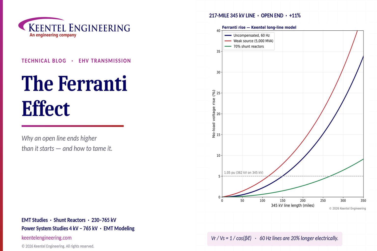
Explore the Ferranti effect in EHV transmission lines: voltage rise, 345 kV examples, switching overvoltages, shunt reactor sizing and mitigation.
By SANDIP R PATEL
•
October 21, 2026
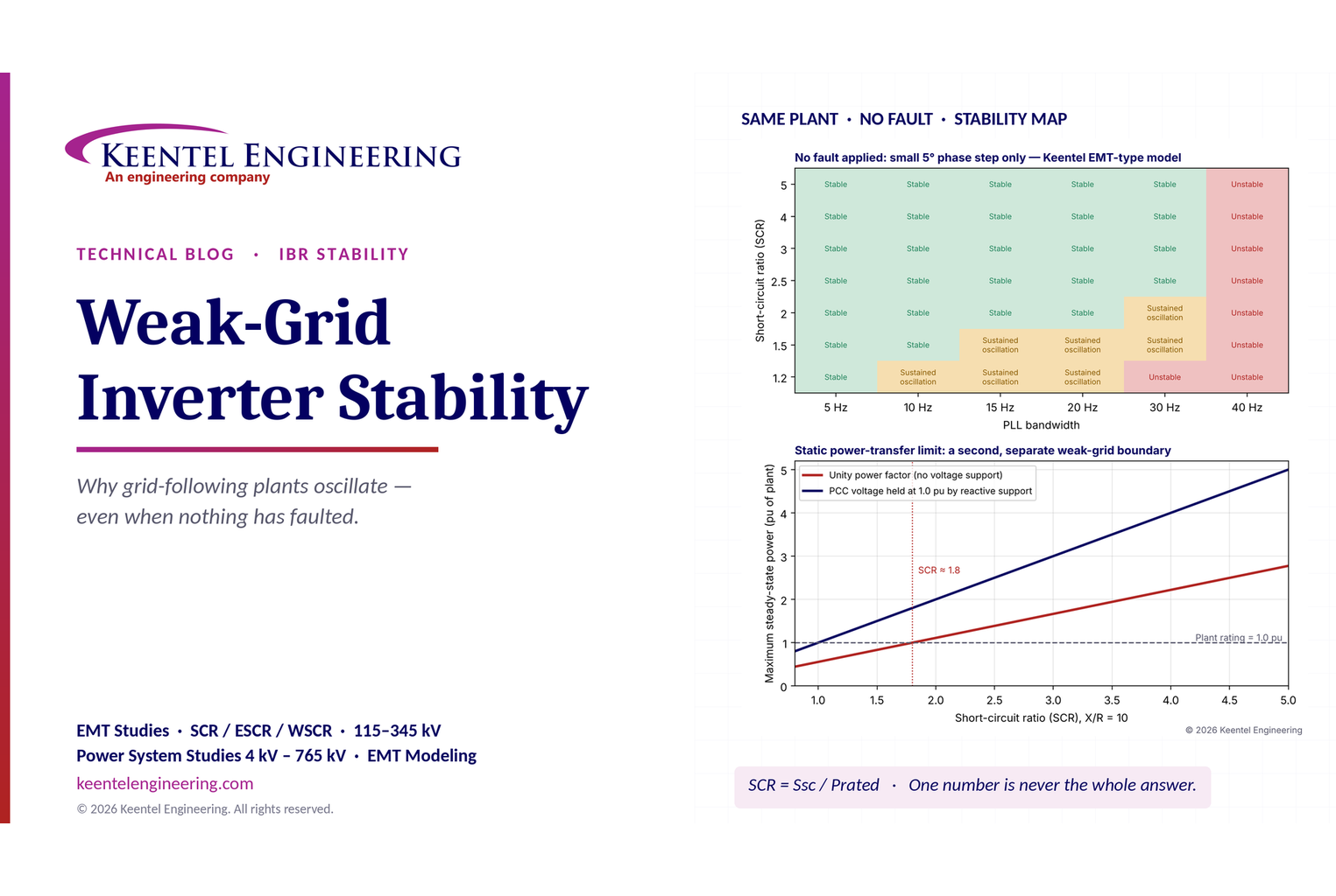
Learn why grid-following inverters become unstable without grid faults. Explore SCR, PLL interactions, EMT studies, grid strength, and mitigation.
By SANDIP R PATEL
•
October 21, 2026
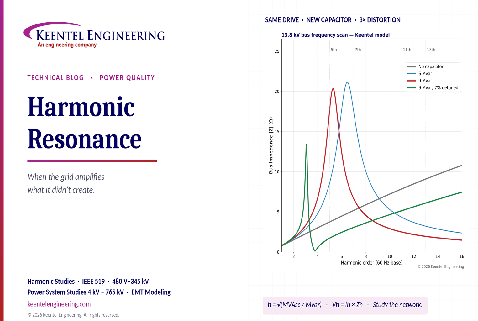
Learn how harmonic resonance amplifies distortion in power systems. Explore capacitor banks, detuned reactors, frequency scans, and IEEE 519 solutions.
By SANDIP R PATEL
•
October 20, 2026
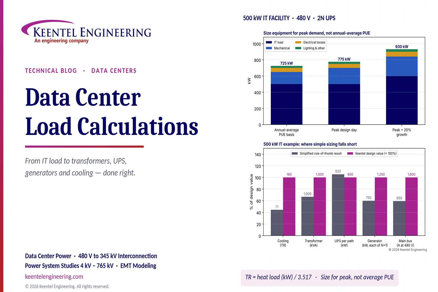
Learn data center electrical load calculations, including IT demand, PUE, UPS and generator sizing, cooling loads, redundancy, and worked US examples.
By SANDIP R PATEL
•
October 20, 2026
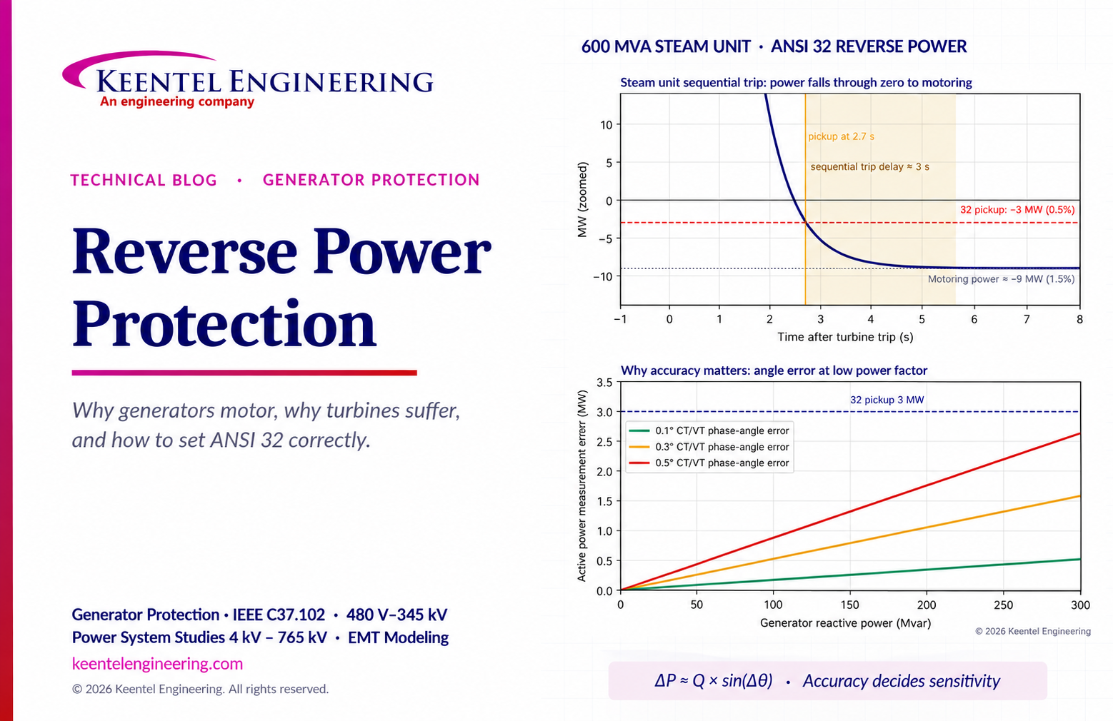
Learn reverse power protection (ANSI 32), generator motoring, relay pickup settings, time delays, sequential tripping and testing for US power plants.
Copy

By Team 2 Dexora
•
October 20, 2026
Explore grounding system testing with Keentel Engineering. Learn IEEE 80/81 methods, soil resistivity, ground resistance, and touch and step voltage safety.

By SANDIP R PATEL
•
October 13, 2026
Plan data center capacity with land screening, MW-per-acre estimates, grid power availability and interconnection feasibility studies from Keentel Engineering.

By SANDIP R PATEL
•
October 11, 2026
Learn which fault produces the highest current at a bus, why SLG faults can exceed three-phase faults, and how symmetrical components determine fault duty.

By SANDIP R PATEL
•
October 11, 2026
Learn why zero-sequence current pulsates in the dq0 frame, how Park's transformation works, and how inverter controls handle unbalance and ground faults.





