
A Coordinated Electric System Interconnection Review—the utility’s deep-dive on technical and cost impacts of your project.
Challenge: Frequent false tripping using conventional electromechanical relays
Solution: SEL-487E integration with multi-terminal differential protection and dynamic inrush restraint
Result: 90% reduction in false trips, saving over $250,000 in downtime
The three operating regions you have to design to
Vector Groups: Which Way Does the Thirty Degrees Go?
, September 3, 2026 | Blog
Reading Transformer Clock Notation Correctly, Why the IEC Preferred Group and the ANSI Standard Displacement Are Opposite, and What the Connection Decides About Grounding, Harmonics, Protection and Paralleling
1. Executive Summary
Transformer vector group notation is treated as a piece of trivia to be memorised: capital letter for the high-voltage winding, lowercase for the low-voltage, a letter for the neutral, a number for the clock position. It is in fact a compact statement about four separate system properties — the phase displacement between windings, whether each side of the transformer is a zero-sequence source, how triplen harmonics and unbalanced load are handled, and whether this transformer can be paralleled with that one.
It is also routinely stated backwards. The most common error, and one that appears in widely circulated explanations of the delta / grounded-wye connection at clock position eleven, is the direction of the phase shift. At position eleven, the low-voltage phasor leads the high-voltage phasor by thirty degrees. It does not lag. Position one is the lagging case. An explanation that says both things in the same document — and several do — is telling the reader that the author has not needed to use the number.
For engineers working to North American standards there is a second and more consequential point. The IEC preferred delta / grounded-wye distribution connection places the low-voltage phasor at eleven o’clock, leading. The ANSI standard angular displacement for delta-wye transformers is the opposite: the high-voltage side leads the low-voltage side by thirty degrees, which corresponds to clock position one. Equipment supplied to the North American standard therefore does not have the displacement the popular explanations describe, and an engineer who applies the eleven o’clock relationship to an ANSI-standard transformer will get a differential relay setting, a paralleling assessment, or a phasing check wrong.
This paper reads the notation properly, explains where the thirty degrees comes from and which way it goes, sets out the IEC and ANSI conventions side by side, and then works through what the connection actually decides: zero-sequence behaviour on each side, triplen harmonic circulation, unbalanced load performance, differential protection compensation and zero-sequence removal, the ground coordination boundary the transformer creates, paralleling compatibility, and the phase shift bookkeeping that matters in any network with more than one path. It closes with a verification section and a twenty-five question FAQ.
The two corrections to carry away
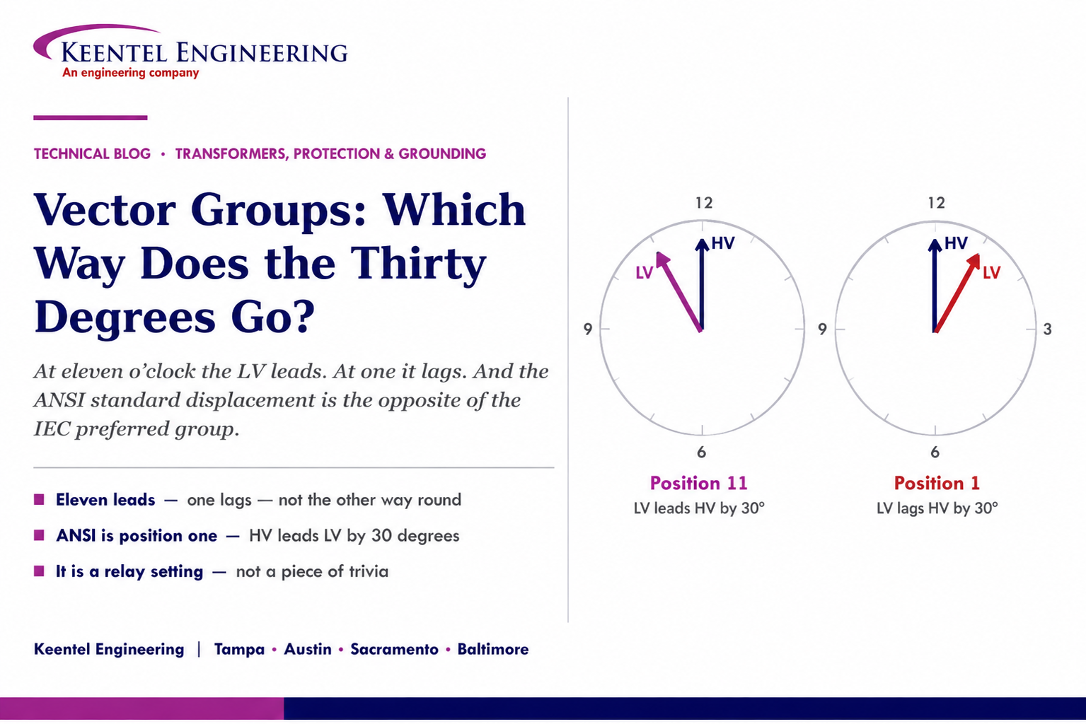
At clock position eleven the low-voltage phasor leads the high-voltage phasor by thirty degrees. Position one is the lagging case.
The ANSI standard displacement for a delta-wye transformer is high-voltage leading low-voltage by thirty degrees — the position one relationship, not position eleven. If you are buying to the North American standard, that is what you are getting.
2. Reading the Notation
The notation is positional and each element carries information.
- The first character, in upper case, is the connection of the highest-voltage winding: D for delta, Y for wye or star, Z for zigzag.
- The following character, in lower case, is the connection of the next winding: d, y or z.
- An N or n indicates that the neutral of that winding is brought out to a terminal. Upper case with the high-voltage winding, lower case with the low-voltage. A wye winding whose neutral is not brought out is written without it, and that is a real distinction — a wye winding with no accessible neutral cannot be grounded and cannot serve line-to-neutral load.
- The final number is the clock position of the low-voltage phasor relative to the high-voltage phasor placed at twelve o’clock, with each hour representing thirty degrees.
Three-winding transformers extend the same scheme in order of decreasing voltage, so a designation such as high-voltage wye with neutral, medium-voltage wye with neutral, and a delta tertiary is written by concatenating the three descriptions with their respective clock positions. The tertiary is frequently the most consequential winding on the nameplate and the one most often overlooked, because it is what gives an otherwise wye-wye transformer a zero-sequence path and a triplen harmonic circulation route.
3. Where the Thirty Degrees Comes From
The displacement is not a design choice applied on top of the connection. It is a consequence of it.
In a delta winding, each winding limb sits between two line terminals, so the winding voltage is the line-to-line voltage of that side. In a wye winding, each limb sits between a line terminal and the neutral, so the winding voltage is the line-to-neutral voltage. The transformer couples winding to winding, which means it couples a line-to-line quantity on one side to a line-to-neutral quantity on the other.
Line-to-line and line-to-neutral phasors in a balanced three-phase set are displaced by thirty degrees. Connecting a delta to a wye therefore produces a thirty degree displacement between the line voltages of the two sides, unavoidably. The magnitude is fixed by the geometry; the only freedom is the sign, and that is set by which winding ends are connected to which terminals — the winding polarity and the terminal labelling.
That is why delta-wye and wye-delta transformers always carry an odd clock number, and why wye-wye and delta-delta transformers carry an even one. Wye-wye and delta-delta couple like to like, so the displacement is zero or one hundred eighty degrees depending on polarity. Zigzag connections can produce other positions because the winding on each limb is split between two phases
4. Which Way Does It Go?
The convention is fixed and it is worth stating precisely, because the ambiguity in the popular explanations comes from stating it loosely.
The high-voltage phasor is placed at twelve o’clock. The clock number is the position of the corresponding low-voltage phasor, read as the hour hand, moving clockwise. Moving clockwise from twelve corresponds to increasing lag, because phasors rotate anticlockwise by convention.
So position one means the low-voltage phasor sits thirty degrees clockwise of the high-voltage phasor, which is thirty degrees of lag. Position eleven means the low-voltage phasor sits three hundred thirty degrees clockwise, which is the same as thirty degrees anticlockwise — thirty degrees of lead.
Position 11 → LV leads HV by 30° Position 1 → LV lags HV by 30°
Stating it as a lag of three hundred thirty degrees is arithmetically correct and practically useless, because nobody sets a relay or checks a phasing to three hundred thirty degrees. Express it as a lead of thirty degrees and the sign is unambiguous.
The self-contradiction to watch for
A summary that says the low-voltage phasor at eleven o’clock "leads by thirty degrees or lags by three hundred thirty" and then, a few lines later, that the "phase displacement is thirty degrees, LV lags HV," has contradicted itself. The second statement describes position one.
This is not a pedantic catch. The sign is what a differential relay setting, a paralleling check, and a synchronising check all depend on.
5. IEC and ANSI Do Not Agree
| IEC preferred distribution practice | ANSI standard displacement | |
|---|---|---|
| How it is described | Clock notation on the nameplate | A stated angular displacement, with terminal markings defined by the standard |
| Delta-wye relationship | Low-voltage phasor at eleven o’clock — LV leads HV by 30° | High-voltage leads low-voltage by 30° — equivalent to the position one relationship |
| Consequence for a design | A transformer described as the eleven o’clock group behaves as described in most international literature | A transformer supplied to the North American standard has the opposite sign, whatever the literature says |
| Where it bites | Applying North American equipment against international guidance | Applying international guidance to North American equipment |
Neither convention is wrong. What is wrong is assuming one applies when the equipment was built to the other. The nameplate is the authority, and where a project mixes equipment from both traditions — increasingly common with imported converter and pad-mount transformers — the vector group of every unit belongs in the design record, not in the assumption that they all match.
6. What the Delta Actually Does
The delta winding is usually credited with reducing harmonics and providing a path for circulating current. Both statements are true and both are usually left unexplained, which makes them impossible to apply.
6.1 Triplen Harmonics and the Magnetising Current
Transformer cores are non-linear, so a sinusoidal flux requires a magnetising current containing a substantial third harmonic. In a set of three-phase quantities, third harmonics and their odd multiples are in phase in all three phases — they are zero-sequence quantities. If the winding arrangement provides no path for them, they cannot flow, and the flux is forced to distort instead. The distorted flux induces a third-harmonic voltage, which appears as neutral displacement and waveform distortion.
A delta winding provides a closed loop in which those in-phase currents can circulate. The magnetising current can then contain its third harmonic, the flux stays close to sinusoidal, and the voltage waveform stays clean. That is the mechanism behind the claim, and it is why a wye-wye transformer without a delta tertiary is a problematic machine.
6.2 Triplen Harmonics From the Load
The same mechanism applies to load-generated harmonics, and this is where it matters commercially. Single-phase non-linear load — the switched-mode power supplies in information technology equipment, lighting drivers, small drives — produces third-harmonic current that is in phase across the three phases and therefore adds arithmetically in the neutral rather than cancelling. Fed from the wye side of a delta-wye transformer, that triplen current circulates in the delta and does not propagate to the high-voltage system.
Two consequences follow. It is genuinely useful, and it is why this connection is the workhorse for buildings and data centres with heavy single-phase electronic load. And the delta winding has to carry that circulating current continuously, which is a rating consideration on transformers serving high-harmonic load. The delta does nothing whatever for non-triplen harmonics — the fifth, seventh, eleventh and thirteenth pass straight through, transformed but not attenuated.
6.3 The Zero-Sequence Consequence
Because the delta permits zero-sequence current to circulate within itself but not to pass through to the other winding, a transformer with a delta winding facing the system is not a zero-sequence source to that system. For a delta / grounded-wye transformer this means the high-voltage side sees no zero-sequence path through the transformer at all. That single fact is the most consequential system property of the connection and it is absent from most explanations.
7. What the Grounded Wye Actually Does
On the low-voltage side, the grounded wye does three things.
- It provides a neutral for line-to-neutral load, which is the reason distribution transformers use it.
- It establishes the system’s voltage reference to earth, which bounds the voltage on unfaulted phases during a ground fault and permits arresters and insulation to be selected on that basis.
- It is a zero-sequence source for the low-voltage system. Ground fault current on the low-voltage side flows through the neutral, and the delta on the other side supplies the ampere-turn balance that makes it possible. The magnitude is set by the transformer’s zero-sequence impedance, which for this connection is comparatively low — which is why delta / grounded-wye distribution transformers produce substantial ground fault current on the low-voltage side.
The engineering point worth holding onto is that the zero-sequence current on the low-voltage side is a transformer property, not a property of whatever is connected on the high-voltage side. This is the same argument that governs ground fault current at inverter-based plants: the sources behind the delta contribute no zero-sequence current, and the grounded-wye winding supplies it all.
8. Zero Sequence Across the Transformer
Reading a vector group as a statement about the zero-sequence network is the fastest way to make it useful. The following covers the connections encountered most often.
| Connection | HV side zero-sequence | LV side zero-sequence | Notes |
|---|---|---|---|
| Delta / grounded wye | No path — not a grounding source to the HV system | Grounded-wye winding is a zero-sequence source with comparatively low impedance | The standard distribution connection. Isolates HV and LV zero-sequence networks completely |
| Grounded wye / delta | Grounded-wye winding is a zero-sequence source to the HV system | No path — LV system requires separate grounding provision | Common for generator step-up and for grounding banks. Makes the plant a grounding source to the transmission system |
| Grounded wye / grounded wye, no tertiary | Path exists but the impedance depends on core construction, not on the connection | Same | The case most often modelled wrongly. Three-legged core form behaves differently from shell form or five-legged designs |
| Grounded wye / grounded wye with delta tertiary | Path exists; the tertiary provides the ampere-turn balance and largely sets the impedance | Same | The tertiary must be rated for the circulating current it will carry |
| Delta / delta, or any ungrounded wye in the path | No path | No path | No grounding reference either side. Ground fault detection and overvoltage both need deliberate provision |
| Zigzag | Provides a low zero-sequence impedance path by construction | Depends on the arrangement | The basis of most grounding banks |
9. Unbalanced Load
The claim that the delta / grounded-wye connection handles unbalanced load well is correct, and the mechanism is the same one as before.
An unbalanced three-phase load draws a zero-sequence current component that must return through the neutral. In a delta / grounded-wye transformer, that current is supported by circulation in the delta, so the neutral point stays close to earth potential and the phase voltages stay balanced even under substantial load unbalance. In a wye-wye transformer with no delta and no other zero-sequence path, the same unbalance shifts the neutral point, and the phase voltages become unequal — one phase rising while another falls, which is the classic neutral instability failure.
This is why the connection dominates in distribution, where load unbalance is normal and uncontrolled, and it is a genuine advantage rather than a marketing claim.
10. Protection: Differential Compensation
Transformer differential protection compares current entering the protected zone with current leaving it. Across a delta-wye transformer, three things prevent the raw measurements from balancing, and all three must be corrected before the comparison means anything.
- The turns ratio. Current magnitudes differ by the ratio, corrected by tap or scaling settings.
- The phase displacement. The thirty degree shift means the currents on the two sides are not in phase even under perfectly healthy load, so the relay must rotate one set to align with the other. The rotation applied is determined by the vector group.
- Zero-sequence current. On the grounded-wye side, an external ground fault produces zero-sequence current that has no counterpart on the delta side, because the delta blocks it. Left uncorrected, that appears as differential current for a fault outside the zone. It must be removed from the wye-side measurement.
In electromechanical practice all three were handled by the current transformer connections — delta-connected current transformers on the wye side of the transformer performed both the rotation and the zero-sequence removal, which is why the old rule of thumb was to connect the CTs opposite to the winding. Modern numerical relays do it internally, and the engineer instead enters the vector group as a setting.
That change moved the error from the wiring to the settings file, and it did not eliminate it. A vector group setting that does not match the transformer produces a standing differential current proportional to load, and the outcome depends on the sensitivity: either the relay operates on energisation or under load, or — worse — it has been desensitised to accommodate the standing quantity and no longer protects. Zero-sequence removal is a separate setting and it is a separate opportunity to get it wrong.
A commissioning check worth insisting on
Verify the differential quantities under load, not only by injection. With the transformer carrying real load and healthy, the differential current should be near zero. A standing differential quantity that grows with load is a compensation error and it is visible in minutes.
Record the result. It is also the baseline that identifies a current transformer problem later.
11. Protection: The Ground Coordination Boundary
A delta-wye transformer creates a hard boundary in the zero-sequence network, and that boundary has a direct consequence for ground fault coordination that is easy to state and often overlooked.
A ground fault on the low-voltage side produces zero-sequence current on the low-voltage side only. The high-voltage side sees the fault transformed into positive- and negative-sequence quantities, so a high-voltage residual overcurrent element sees essentially nothing. That means a high-voltage ground element cannot provide backup for a low-voltage ground fault, and it cannot be coordinated against one. Backup for low-voltage ground faults has to come from a phase element on the high-voltage side, or from a low-voltage element, or from the transformer’s own neutral protection.
The same boundary is why restricted earth fault protection on the wye winding is worth having: it is a unit function covering the zone the differential covers poorly for faults near the neutral, and it is not defeated by the zero-sequence isolation.
For a grounded-wye / delta transformer the picture inverts. The high-voltage side is a zero-sequence source, so the transformer contributes ground fault current to the high-voltage system and appears as an infeed to the utility’s ground protection, whether or not anything is generating behind it. That property is a design decision with coordination consequences, and it is one of the more common findings in interconnection review.
12. Paralleling and Replacement
Two transformers can be operated in parallel only if their voltages match in magnitude and in phase at every instant. Vector group is the phase half of that requirement, and it is the one that produces the most dramatic failures when it is wrong.
The conditions for parallel operation are the same voltage ratio at every tap position, the same phase displacement, matched percentage impedance within a reasonable tolerance so that load divides sensibly, the same phase sequence, and compatible tap arrangements. A mismatch in ratio or impedance produces circulating current and unequal loading. A mismatch in phase displacement produces a voltage difference across the paralleling point of the order of half the system voltage, and the result is a fault.
Certain combinations from different clock groups can be made compatible by external connection changes — relabelling terminals and rolling phases — and there are standard arrangements for doing so. They must be engineered deliberately, drawn, and verified by phasing measurement, not applied from memory in the field.
The practical case where this arrives without warning is replacement. A failed unit in an established bank is replaced with the nearest available equivalent, which matches on rating and impedance and differs on vector group — often because the replacement was procured to a different standard from the original. The nameplate carries the information; whether anyone reads it before the paralleling attempt is the question.
13. Phase Shift Around a Loop
In a network with more than one path between two points, the total phase displacement around the loop must be zero, or a multiple of three hundred sixty degrees. Otherwise the two paths present different phase angles at the point where they meet and circulating current flows continuously, loading the transformers and the conductors with current that serves no purpose.
This becomes a live issue in a few recognisable situations: a network with two transformation stages where one path uses two delta-wye transformers and the other uses one; a substation with a normally open tie that someone proposes to close; an industrial plant with alternate supplies from different points in the utility network; and any closed-transition transfer scheme where two sources are momentarily paralleled.
The bookkeeping is straightforward once someone does it: sum the displacements around every loop the system can form, including the ones the operating philosophy says will never be closed but the switching arrangement permits. The failure mode is not subtle when it occurs, and it is entirely avoidable at design.
14. Where Vector Group Shows Up in Project Work
- Interconnection. The displacement between the plant and the system affects synchronising, closed-transition transfer, and any parallel path, and the transformer connection determines whether the plant is a grounding source at the point of interconnection.
- Generator step-up design. The connection sets the relationship between machine terminal phasors and system phasors, which matters for synchronising, for relay polarising quantities, and for the sequence networks used in every study.
- Inverter-based plants. The main transformer connection decides whether the plant contributes ground fault current to the system, and the collector-side arrangement decides whether the collector system has a grounding reference at all. Pad-mount transformer connections determine whether collector zero-sequence quantities reach the inverters.
- Data centres and buildings with heavy single-phase electronic load. The delta winding’s triplen circulation is a genuine benefit, and the corresponding rating consideration on the delta and on the neutral conductor is a genuine design item.
- Protection settings. Differential compensation and zero-sequence removal are vector group settings, and the ground coordination boundary follows from the connection.
- Studies. The sequence networks used for short circuit, ground fault, and coordination work are built from the connections. A vector group entered wrong in a model produces plausible and incorrect results.
- Procurement and replacement. The nameplate group must be specified, not inherited, particularly where equipment is sourced across standards frameworks.
15. Verification by Test
The nameplate states the vector group and the factory test report confirms it, but the connection that matters is the one as installed and terminated.
- Factory polarity and phase-relation test. Performed as part of the standard test sequence and reported. Obtain the report and read it rather than relying on the nameplate alone.
- Site ratio and polarity verification. Confirms that the unit delivered is the unit ordered and that terminations match the drawings.
- Phase sequence verification on both sides, independently, before any connection to a live system.
- Phasing check across every point where two sources can be paralleled, measured rather than assumed, including points that the operating philosophy says will never be paralleled but the switchgear permits.
- Differential quantities under load at commissioning, as described in Section 10, which verifies the relay compensation against the transformer as installed.
- Record all of it. The vector group of every transformer in the system belongs in the design record and in the single-line diagram, because the next engineer to modify the system will otherwise assume.
16. Reading the Source Correctly
The direction of the shift
At clock position eleven the low-voltage phasor leads the high-voltage phasor by thirty degrees. Any statement that it lags by thirty degrees describes position one. A document that contains both statements has contradicted itself, and the lagging version is the incorrect one for the eleven o’clock group.
"Most commonly used" depends on where you are
The eleven o’clock delta / grounded-wye group is the preferred distribution connection under IEC practice. The ANSI standard displacement for delta-wye transformers is the opposite sign. Both statements are true in their own framework, and applying one to equipment built to the other is the error the popular explanations set the reader up for.
"Reduces harmonics" needs its mechanism
The delta provides a circulation path for zero-sequence — triplen — currents. That keeps the magnetising current’s third harmonic flowing so the flux stays sinusoidal, and it stops load-generated triplen current from propagating to the high-voltage system. It does nothing for the fifth, seventh, eleventh or thirteenth harmonics, which pass through. Stated without the mechanism, the claim invites the wrong conclusion in a harmonic study.
The most consequential property is missing
A delta winding facing the system means the transformer is not a zero-sequence source on that side. For a delta / grounded-wye transformer the high-voltage side has no zero-sequence path through the transformer at all, which determines ground fault current distribution, ground relay coordination across the transformer, and whether the installation provides a grounding reference. None of the popular explanations mention it, and it is the property that decides the most design questions.
So is the protection consequence
Vector group is a differential relay setting. Enter it wrongly and the relay carries a standing differential current proportional to load, which either causes an operation or, if the sensitivity was relaxed to accommodate it, leaves the transformer unprotected. That is what the number is for in daily practice.
17. Keentel Electrical Power Engineering Services
Keentel Engineering works across the design, study, protection and commissioning questions that a transformer connection decides.
17.1 Transformer Application and Specification
- Connection and vector group selection against the system requirement, including grounding role, harmonic duty, unbalanced load, and paralleling compatibility with existing equipment.
- Transformer specification including winding connection, neutral arrangement, tertiary requirement, zero-sequence impedance requirements and factory test scope, and converter duty where applicable.
- Replacement and paralleling assessment, including compatibility review and the external connection changes required where groups differ.
- Harmonic loading assessment and derating evaluation for transformers serving non-linear load.
17.2 Grounding and System Studies
- System grounding design and effective grounding assessment, including whether and where the transformer provides a grounding reference.
- Sequence network development and short-circuit studies with transformer connections and zero-sequence impedances represented from test data rather than assumed.
- Ground fault overvoltage analysis, surge arrester selection review, and grounding transformer specification and sizing.
- Load flow, coordination, arc-flash, harmonic and power quality studies, and electromagnetic transient analysis where required.
17.3 Protection and Control
- Transformer differential protection design and settings, including vector group compensation, zero-sequence removal, harmonic restraint, and current transformer sizing and saturation assessment.
- Restricted earth fault, neutral overcurrent, and mechanical protection application.
- Ground fault coordination across transformation boundaries, and settings audits against the study of record.
- Protection scheme design, relay panel and schematic design, and substation automation integration.
17.4 Commissioning and Owner’s Engineer Support
- Commissioning specification and test procedures including polarity, ratio, phase sequence, phasing, and verification of differential quantities under load.
- Design review of EPC and vendor submittals, QA/QC of third-party study packages, and factory test report review.
- Failure and misoperation investigation where a transformer protection scheme has operated incorrectly or a paralleling attempt has failed.
Keentel Engineering holds a Florida Certificate of Authorization and maintains offices in Tampa, Austin, Sacramento, and Baltimore, supporting projects across the interconnections.
18. Frequently Asked Questions
Q1. What does the vector group notation actually mean?
The upper-case letter is the connection of the highest-voltage winding, the lower-case letter the next winding, an N or n means that winding’s neutral is brought out, and the number is the clock position of the low-voltage phasor relative to the high-voltage phasor at twelve o’clock, each hour representing thirty degrees.
Q2. At clock position eleven, does the low voltage lead or lag?
It leads by thirty degrees. The clock number is read clockwise from twelve, and clockwise corresponds to lag, so eleven means three hundred thirty degrees of lag — which is thirty degrees of lead. Position one is the lagging case.
Q3. Why do so many explanations say it lags?
Because three hundred thirty degrees of lag and thirty degrees of lead are the same thing, and the shorthand gets truncated to "thirty degrees" with the wrong sign attached. Several widely shared summaries state both versions in the same document. Express it as a lead of thirty degrees and the ambiguity disappears.
Q4. Is the eleven o’clock group really the most common?
Under IEC practice it is the preferred distribution connection. The ANSI standard angular displacement for delta-wye transformers is the opposite: the high-voltage side leads the low-voltage side by thirty degrees, which is the position one relationship. Equipment supplied to the North American standard therefore does not have the eleven o’clock relationship.
Q5. Does that mean one convention is wrong?
No. Both are correct within their own framework. What is wrong is assuming one applies when the equipment was built to the other. The nameplate is the authority, and on projects mixing equipment from both traditions the vector group of every unit belongs in the design record.
Q6. Where does the thirty degrees physically come from?
From coupling a line-to-line quantity to a line-to-neutral quantity. In a delta the winding voltage is the line-to-line voltage; in a wye it is the line-to-neutral voltage. Those two phasors are thirty degrees apart in a balanced set, so a delta-wye connection produces a thirty degree displacement unavoidably. Only the sign is a design choice, set by winding polarity and terminal labelling.
Q7. Why are delta-wye groups always odd numbers?
Because they couple unlike quantities and therefore always produce a displacement that is an odd multiple of thirty degrees. Wye-wye and delta-delta couple like to like, so they produce zero or one hundred eighty degrees — even numbers. Zigzag connections can produce other positions because each limb’s winding is split between phases.
Q8. What does the delta winding do about harmonics, exactly?
It provides a closed loop in which zero-sequence — triplen — currents can circulate. That lets the magnetising current carry its third harmonic so the core flux stays sinusoidal, and it stops load-generated triplen current on the wye side from propagating to the high-voltage system. It does nothing for the fifth, seventh, eleventh or thirteenth harmonics.
Q9. Why does that matter for data centres and commercial buildings?
Because single-phase electronic load produces third-harmonic current that is in phase across the three phases and adds in the neutral rather than cancelling. Fed from the wye side of a delta-wye transformer, that current circulates in the delta instead of reaching the high-voltage system — a genuine benefit, and a continuous rating consideration for the delta winding and the neutral conductor.
Q10. What is the most consequential property of the delta / grounded-wye connection?
That the high-voltage side has no zero-sequence path through the transformer. The delta permits circulation within itself but not transfer, so the transformer is not a grounding source to the high-voltage system. That determines ground fault current distribution, ground relay coordination across the transformer, and whether the installation provides a grounding reference — and it is absent from most explanations.
Q11. And on the low-voltage side?
The grounded-wye winding is a zero-sequence source for the low-voltage system, with comparatively low zero-sequence impedance, which is why this connection produces substantial low-voltage ground fault current. The magnitude is a transformer property, not a property of whatever is connected on the high-voltage side.
Q12. Can a high-voltage ground element back up a low-voltage ground fault?
No. The delta isolates the zero-sequence networks, so a low-voltage ground fault produces no residual current on the high-voltage side. Backup must come from a high-voltage phase element, a low-voltage element, or the transformer’s neutral protection. Attempting to coordinate a high-voltage ground element against a low-voltage ground fault is a coordination exercise with no physical basis.
Q13. Why is grounded wye / grounded wye without a tertiary a problem?
Because the connection alone does not determine the zero-sequence impedance — core construction does. A three-legged core-form transformer returns zero-sequence flux through the tank and behaves as though a delta were present; a shell-form or five-legged design has a genuine core return path and a very high zero-sequence impedance absent a delta. Identical nameplates, different behaviour.
Q14. Why does the connection help with unbalanced load?
An unbalanced load draws zero-sequence current that must return through the neutral. In a delta / grounded-wye transformer, circulation in the delta supports that current so the neutral stays near earth potential and phase voltages stay balanced. In a wye-wye with no zero-sequence path, the neutral shifts and phase voltages become unequal.
Q15. How does vector group affect differential protection?
The thirty degree displacement means currents on the two sides are out of phase even under healthy load, so the relay must rotate one set to align them, and the rotation is determined by the vector group. Separately, zero-sequence current on the grounded-wye side has no counterpart on the delta side and must be removed, or an external ground fault produces differential current.
Q16. What happens if the vector group setting is wrong in the relay?
A standing differential current proportional to load. Depending on sensitivity, the relay either operates on energisation or under load, or it was desensitised to accommodate the standing quantity and no longer protects the transformer. Both outcomes are bad and both are avoidable.
Q17. How do I check the compensation is right?
Verify the differential quantities with the transformer carrying real load and healthy. The differential current should be near zero, and a standing quantity that grows with load is a compensation error. It takes minutes, it is more conclusive than injection alone, and the record is also a baseline for identifying a current transformer problem later.
Q18. How was this handled before numerical relays?
By the current transformer connections. Delta-connected current transformers on the wye side of the transformer performed both the phase rotation and the zero-sequence removal — hence the old rule of connecting the CTs opposite to the winding. Numerical relays do it internally, which moved the error from the wiring to the settings file rather than eliminating it.
Q19. What are the conditions for paralleling two transformers?
Same voltage ratio at every tap position, same phase displacement, matched percentage impedance within a reasonable tolerance, same phase sequence, and compatible tap arrangements. Ratio or impedance mismatch produces circulating current and unequal loading. Phase displacement mismatch produces a large voltage difference across the paralleling point and a fault.
Q20. Can transformers of different vector groups ever be paralleled?
Certain combinations can be made compatible by external connection changes — relabelling terminals and rolling phases — and standard arrangements exist. They must be engineered deliberately, drawn, and verified by phasing measurement rather than applied from memory in the field.
Q21. Where does this catch people in practice?
Replacement. A failed unit is replaced with the nearest available equivalent that matches on rating and impedance and differs on vector group, frequently because it was procured to a different standard from the original. The nameplate carries the information; whether anyone reads it before the paralleling attempt is the question.
Q22. What is the loop phase shift issue?
In a network with more than one path between two points, the total displacement around the loop must sum to zero or a multiple of three hundred sixty degrees. Otherwise the paths present different angles where they meet and circulating current flows continuously. It arises with multiple transformation stages, normally open ties that someone proposes to close, alternate supplies from different network points, and closed-transition transfer schemes.
Q23. Does vector group matter for inverter-based plants?
Considerably. The main transformer connection decides whether the plant is a zero-sequence source at the point of interconnection, which governs ground fault current, effective grounding, and utility ground relay coordination. The collector-side arrangement decides whether the collector system has a grounding reference at all, and the pad-mount transformer connections decide whether collector zero-sequence quantities reach the inverters.
Q24. What should be verified at commissioning?
Factory polarity and phase-relation test report reviewed rather than assumed; site ratio and polarity verification; phase sequence on both sides independently; phasing measured at every point where two sources can be paralleled, including points the operating philosophy says will never be paralleled but the switchgear permits; and differential quantities under load.
Q25. What is the one habit worth adopting?
Put the vector group of every transformer on the single-line diagram and in the design record. The number is a statement about grounding, harmonics, protection compensation and paralleling compatibility all at once, and the next engineer to modify the system will otherwise assume — usually that everything matches, and usually at the moment that assumption is most expensive.
References and Further Reading
The following are referenced by subject in the body of this document. The current published edition of each standard governs its own requirements, and the transformer nameplate and factory test report govern any application decision for a specific unit.
Transformer Standards and Connections
- IEC 60076-1, Power transformers — General, which establishes the connection symbol and clock notation convention, together with the application guidance in the IEC 60076 series — International Electrotechnical Commission
https://webstore.iec.ch/ - IEEE Std C57.12.00, General Requirements for Liquid-Immersed Distribution, Power, and Regulating Transformers — including the standard angular displacement requirement for delta-wye and wye-delta connections — IEEE Standards Association
https://standards.ieee.org/ - IEEE Std C57.12.70, Standard for Terminal Markings and Connections for Distribution and Power Transformers — IEEE Standards Association
https://standards.ieee.org/ - IEEE Std C57.12.90, Standard Test Code for Liquid-Immersed Distribution, Power, and Regulating Transformers — including polarity, phase relation and zero-sequence impedance measurement — IEEE Standards Association
https://standards.ieee.org/ - IEEE Std C57.105, Guide for Application of Transformer Connections in Three-Phase Distribution Systems — the standing reference on what each connection does in a system context — IEEE Standards Association
https://standards.ieee.org/
Protection, Grounding, and Studies
- IEEE Std C37.91, Guide for Protecting Power Transformers — covering differential compensation, zero-sequence removal, harmonic restraint and the mechanical protections — IEEE Standards Association
https://standards.ieee.org/ - IEEE Std C57.109, Guide for Liquid-Immersed Transformer Through-Fault-Current Duration, and IEEE Std C57.110 for transformer capability with non-sinusoidal load current — IEEE Standards Association
https://standards.ieee.org/ - IEEE Std C62.92 series, Guide for the Application of Neutral Grounding in Electrical Utility Systems, and IEEE Std 142 (Green Book) for industrial and commercial grounding — IEEE Standards Association
https://standards.ieee.org/ - IEEE Std C37.110, Guide for the Application of Current Transformers Used for Protective Relaying Purposes, and IEEE Std C57.13 for instrument transformer requirements — IEEE Standards Association
https://standards.ieee.org/ - IEEE Std 3002.3 for short-circuit studies and IEEE Std 519 for harmonic control, where transformer connections enter the sequence networks and the harmonic path — IEEE Standards Association
https://standards.ieee.org/
Notice and Disclaimer
This document is original technical content prepared by Keentel Engineering LLC for general professional information. It is not project-specific engineering advice and does not constitute a design, a study, a protection setting, or an equipment specification for any installation. Transformer connection selection, protection compensation, paralleling assessment and grounding design must be established by project-specific analysis using the nameplate data and factory test results for the specific units involved.
Conventions described here reflect the standards frameworks referenced. Where an installation includes equipment supplied under different frameworks, the nameplate and factory test report for each unit govern, and no general convention should be assumed to apply across a mixed population.
Keentel Engineering LLC is an independent engineering consultancy. Reference to any standard, code, industry organisation, regulator, or equipment category in this document does not imply affiliation with, endorsement by, or sponsorship from any such organisation or manufacturer.

About the Author:
Sandip "Sonny" R. Patel, P.E.
IEEE Senior Member · Founder & CEO, Keentel Engineering
In 1995, Sonny Patel earned his Electrical Engineering degree from the University of Illinois. But degrees don't build legacies — action does.
For three decades, he has worked the power industry from every side of the table: 16 years as a utility engineer at Exelon/Commonwealth Edison; generation leadership across hydroelectric, industrial steam turbine, and a 9 GW renewable fleet; NERC Regional Entity Senior Compliance Engineer and Audit Team Lead, auditing some of the nation's largest utilities; and testing and commissioning lead on equipment up to 765 kV — the very top of the North American grid.Utility. Generator. Regulator. Consultant. Few engineers have seen all four seats. Fewer still have sat in them.
His experience spans nuclear, hydro, conventional generation, renewables, oil and gas, mining — and today's data centers, where he is authoring a three-book series on data center design. He is a Licensed Professional Engineer in six states and a Licensed Electrical Contractor in Florida (Unlimited EC) — he doesn't just design the work; he's qualified to stand behind its execution.Today, as Founder and CEO of Keentel Engineering, Sonny leads a nationwide team of engineers delivering substation design, power system studies, NERC compliance, and commissioning — done right, coast to coast.Three decades. Every side of the table. One standard: accountable engineering.
Services

Let's Discuss Your Project
Let's book a call to discuss your electrical engineering project that we can help you with.
About the Author:
Sandip "Sonny" R. Patel, P.E.
IEEE Senior Member · Founder & CEO, Keentel Engineering
In 1995, Sonny Patel earned his Electrical Engineering degree from the University of Illinois. But degrees don't build legacies — action does.
For three decades, he has worked the power industry from every side of the table: 16 years as a utility engineer at Exelon/Commonwealth Edison; generation leadership across hydroelectric, industrial steam turbine, and a 9 GW renewable fleet; NERC Regional Entity Senior Compliance Engineer and Audit Team Lead, auditing some of the nation's largest utilities; and testing and commissioning lead on equipment up to 765 kV — the very top of the North American grid.
Utility. Generator. Regulator. Consultant. Few engineers have seen all four seats. Fewer still have sat in them.
His experience spans nuclear, hydro, conventional generation, renewables, oil and gas, mining — and today's data centers, where he is authoring a three-book series on data center design. He is a Licensed Professional Engineer in six states and a Licensed Electrical Contractor in Florida (Unlimited EC) — he doesn't just design the work; he's qualified to stand behind its execution.
Today, as Founder and CEO of Keentel Engineering, Sonny leads a nationwide team of engineers delivering substation design, power system studies, NERC compliance, and commissioning — done right, coast to coast.Three decades. Every side of the table. One standard: accountable engineering.
Leave a Comment
Thank you for contacting us.
We will get back to you as soon as possible.
We will get back to you as soon as possible.
Oops, there was an error sending your message.
Please try again later.
Please try again later.
Related Posts

By SANDIP R PATEL
•
October 13, 2026
Plan data center capacity with land screening, MW-per-acre estimates, grid power availability and interconnection feasibility studies from Keentel Engineering.

By SANDIP R PATEL
•
October 11, 2026
Learn which fault produces the highest current at a bus, why SLG faults can exceed three-phase faults, and how symmetrical components determine fault duty.

By SANDIP R PATEL
•
October 11, 2026
Learn why zero-sequence current pulsates in the dq0 frame, how Park's transformation works, and how inverter controls handle unbalance and ground faults.

By SANDIP R PATEL
•
October 11, 2026
Explore grid inertia, RoCoF and frequency response, with swing equation calculations, frequency nadir analysis and US power system simulation examples.

By SANDIP R PATEL
•
October 11, 2026
Learn transient stability analysis, swing equation, equal-area criterion and critical clearing time with a 345 kV worked example and NERC TPL-001 guidance.

By SANDIP R PATEL
•
October 11, 2026
Learn why inverter controls become unstable in weak grids, how PLL bandwidth and SCR affect stability, and how PSCAD EMT studies identify and mitigate oscillations.

By SANDIP R PATEL
•
October 11, 2026
Learn how STATCOMs improve voltage stability and prevent FIDVR. Explore reactive power sizing, delayed fault clearing, NERC criteria and 138 kV simulation results.

By SANDIP R PATEL
•
October 10, 2026
Learn BESS DC sizing with power, energy, current and C-rate calculations, battery losses, degradation and a 100 MW/400 MWh utility-scale example.

By SANDIP R PATEL
•
October 10, 2026
Learn how BESS ROI is calculated using peak shaving, energy arbitrage, power quality and battery storage economics, with a practical 5 MW/10 MWh example.





