
A Coordinated Electric System Interconnection Review—the utility’s deep-dive on technical and cost impacts of your project.
Challenge: Frequent false tripping using conventional electromechanical relays
Solution: SEL-487E integration with multi-terminal differential protection and dynamic inrush restraint
Result: 90% reduction in false trips, saving over $250,000 in downtime
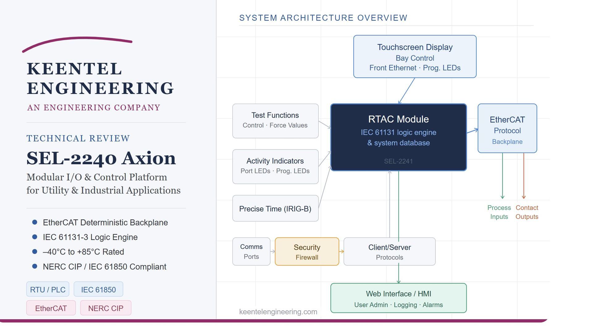
SEL-2240 Axion: The Ultimate Modular I/O and Control Platform for Utility and Industrial Applications A Keentel Engineering Technical Review
May 1, 2026 | Blog
Introduction
In today's demanding utility and industrial automation environments, engineers need control platforms that are rugged, flexible, secure, and deterministic. The SEL-2240 Axion from Schweitzer Engineering Laboratories (SEL) delivers on all four fronts. Whether you're building a remote terminal unit (RTU), a programmable logic controller (PLC), a microgrid controller, or a SCADA data concentrator, the Axion system offers a single, unified hardware and software platform to get the job done.
At Keentel Engineering, we work with automation and protection systems across utility and industrial sectors. This post provides a deep technical review of the SEL-2240 Axion — what it is, how it works, what modules are available, and answers to the questions our engineers and clients ask most often.
What Is the SEL-2240 Axion?
The SEL-2240 Axion is a fully integrated modular system combining:
- Digital I/O (inputs and outputs)
- Analog I/O (DC and AC)
- Current and voltage measurement (CT/PT modules)
- IEC 61131 programmable logic engine (via the RTAC)
- Multi-protocol SCADA communications
- Built-in cybersecurity features
At its heart, the Axion uses the SEL Real-Time
Automation Controller (RTAC) as its CPU and logic engine, combined with a deterministic EtherCAT backplane for high-speed, real-time communication between modules. All of this is packaged in hardware rated from –40°C to +85°C, making it suitable for the harshest substation, industrial, and offshore environments.
System Architecture Overview
The Building Blocks
The Axion system is built around three core hardware elements:
1. SEL-2242 Chassis/Backplane
The chassis is available in three configurations: 10-slot, 4-slot, and Dual 4-slot. Each chassis is the physical mounting structure that houses all modules and provides the EtherCAT backplane interconnect. Mounting options include horizontal rack mount (5U), surface mount, and panel mount.
2. SEL-2241 RTAC Module
This is the brain of the Axion node. It contains the IEC 61131-3 logic engine, communications ports, time synchronization (IRIG-B), web-based HMI capability, and cybersecurity features. Alternatively, a standalone RTAC (such as the SEL-3350) can connect to the Axion node via Ethernet.
3. SEL-2243 Power Coupler
The power coupler serves dual purposes — it supplies power to the node AND provides EtherCAT connectivity to remote Axion nodes. It supports redundant (load-sharing) configurations and accepts both AC (85–264 Vac) and DC (19.1–300 Vdc) input depending on the model.
Two RTAC Configurations
- Embedded: SEL-2241 RTAC module installed directly in Slot A of the Axion chassis
- Standalone: External RTAC (e.g., SEL-3350) connected via Ethernet to the SEL-2240 node
The SEL-2242 backplane with 7-inch touchscreen is only compatible with the SEL-2241 in Slot A important for bay controller applications.
Module Lineup: A Detailed Breakdown
Digital Input SEL-2244-2
- 24 digital inputs with optoisolation
- Supports input voltages of 24, 48, 110, 125, 220, and 250 Vac/Vdc
- Six independent and eighteen common-return inputs
- Rated insulation voltage: 300 Vac; impulse withstand: 4,000 V
- Current draw: 2–8 mA at nominal voltage
- All terminals clearly numbered for wiring and testing
Standard Current Digital Output SEL-2244-3
- 16 relay outputs configurable as all Form A, all Form B, or 8A/8B
- DC make rating: 30 A at 250 Vdc (per IEEE C37.90)
- Continuous carry: 6 A at 70°C / 4 A at 85°C
- AC rating: 240 Vac, 5 A thermal
- Pickup/dropout time ≤ 8 ms typical
- Mechanical durability: 10 million no-load operations
- MOV contact protection: 350 Vdc, 145
Fast High-Current Digital Output SEL-2244-5
- 10 relay outputs (all Form A, all Form B, or 5A/5B)
- Extremely fast pickup: ≤ 12 µs at 250 Vdc (versus 8 ms for standard contacts)
- Inductive breaking capacity: 10 A at 24–125 Vdc (L/R = 40 ms) — significantly higher than SEL-2244-3
- MOV contact protection: 330 Vdc, 145 J
- Ideal for high-speed protection applications
DC Analog Input SEL-2245-2
- 16 analog inputs configurable in pairs as ±20 mA, ±2 mA, or ±10 V
- Sampling rate: 1 ksps with 330 Hz anti-alias filter
- 16-bit ADC; typical accuracy ±0.25% (voltage), ±0.5% (current)
- Three digital filter options: 16 Hz, 10 Hz, 0.2 Hz
- 60 Hz rejection: >60 dB (Filter A), >70 dB (Filters B & C)
- Triggered waveform recording in COMTRADE format
DC Analog Input Extended Range SEL-2245-22
- 4 inputs, 0–300 Vdc range (DC mode) or AC metering mode
- Sampling rate: 24 ksps with 5 kHz anti-alias filter
- Isolation: 2,500 Vrms between inputs and to chassis
- Waveform recording at up to 24 kHz
Low-Voltage (LEA) Monitoring SEL-2245-221
- 4 inputs, 0–30 V peak
- Designed for low-energy analog (LEA) instrument transformer outputs
- Accuracy: ±0.1% RMS typical at nominal frequency
DC Analog Output SEL-2245-3
- 8 outputs configurable as ±20 mA or ±10 V
- Current mode load: 0–750 Ω at 20 mA
- Voltage mode load: >2,000 Ω
- Step response: 1 ms (10%–90%)
- Accuracy: ±0.3% of full scale typical (current), ±0.2% (voltage)
- Isolation: 2,000 Vdc between outputs or ground
- Used for governor/exciter control signals
AC Metering Module SEL-2245-4
- 4 CT + 4 PT inputs with two-wire connections
- Current range: 0.05–22 A continuous (up to 100 A symmetrical for 25 s)
- Voltage range: 5–400 V L-N
- Typical accuracy: ±0.1% fundamental current and voltage
- Provides full power, energy, power factor, sequence components, and synchrophasor measurements
- Synchrophasor conformance: IEEE C37.118.1-2011/C37.118.1a-2014, Level 1
- Waveform recording up to 24 kHz in COMTRADE format
AC Protection Module SEL-2245-42
- 3 CT + 3 PT inputs
- Optimized for protection-class accuracy over a wide dynamic range
- Current operational range: 0.1–300 Arms; thermal withstand: 500 Arms for 1 second
- Voltage operational range: 0–300 VL-N; insulation: 300 VL-N continuous, 600 VL-N for 10 seconds
- Update interval: 250 Hz (both fundamental and RMS)
- Transient fault record: up to 576 seconds at 1 kHz, 24 seconds at 24 kHz
- Channel-to-ground isolation: 2.5 kVrms
Standard Current + LEA Monitoring SEL-2245-411
- 4 CT + 4 LEA inputs — combines standard current transformers with low-energy analog voltage inputs
- Current accuracy: ±0.1% fundamental typical
- LEA voltage accuracy: ±0.1% RMS typical above 50 mV
EtherCAT Network: The Backbone of Determinism
EtherCAT is what makes the Axion truly deterministic. Unlike conventional fieldbuses, EtherCAT processes data on the fly as frames pass through each node — delivering sub-millisecond cycle times across the entire I/O network.
Key EtherCAT Capabilities
- Up to 60 modules or 6 nodes on a single EtherCAT network
- All I/O updated at a deterministic frequency with 1 ms Sequential Events Recorder (SER) timestamps
- Three topology options: Star, Sequential (daisy-chain), and Hybrid
- Node-to-node connections via RJ45 (cable length <3 m) or fiber-optic (multimode: ~2 km; single-mode: ~15 km)
Fiber option enables backplane linking up to 5 km — critical for microgrid and campus-wide applications
Topology Summary
| Topology | Best Used When |
|---|---|
| Star | Physical layout matches a central hub; greater flexibility |
| Sequential | Linear physical arrangement of substations or panels |
| Hybrid | Mix of centralized and distributed physical layouts |
Synchronized Measurements: A Key Differentiator
One of the Axion's most powerful features is synchronized sampling across all CT/PT modules.
- All CT/PT modules in an Axion system sample simultaneously, providing a common time reference for all voltages and currents
- When connected to IRIG-B, measurements are synchronized to the top of the second enabling time-aligned data across geographically dispersed Axion systems
- This eliminates post-processing alignment steps, enabling real-time algorithms for load shedding, autosynchronization, and islanding detection
Applications in Detail
1. Industrial Load Shedding
The Axion combines frequency and power measurements with hundreds of binary I/O points in a single unit. Using the CT/PT module's frequency and power elements, the logic engine implements underfrequency or demand-based load shedding with fast-acting control logic — no separate devices needed.
2. Microgrid Control
With the SEL-2245-4 module adding dozens of voltage/current channels and EtherCAT links spanning up to 5 km, the Axion is purpose-built for microgrid monitoring and control. Synchronized sampling supports islanding detection, generation restoration, and dispatch algorithms.
3. Autosynchronization
Multiple CT/PT modules provide all necessary PT measurements within one system, already time-aligned. The logic engine closes the control loop on governor and exciter outputs via the SEL-2245-3 DC Analog Output module — supporting safe, unattended synchronization.
4. RTU (Remote Terminal Unit)
The Axion supports both distributed RTU (SEL-2241 in each node for autonomous operation) and centralized RTU (one master SEL-2241 managing remote nodes via EtherCAT). Supported SCADA protocols include DNP3, Modbus, IEC 61850, LG 8979, and SEL Fast Message.
5. IEC 61850 GOOSE Concentrator
Gather substation I/O from SEL-2244 modules and publish as GOOSE messages. Non-IEC 61850 relays can be integrated and their data converted to GOOSE format via the RTAC's protocol flexibility.
6. Synchrophasor Concentrator
Collect IEEE C37.118-compliant synchrophasor data from SEL relays and other PMUs via DNP3, including timestamps and quality flags, for delivery to SCADA or wide-area monitoring systems.
7. SCADA Data Concentrator / HMI
Use the embedded web HMI (built with ACSELERATOR Diagram Builder) to provide single-line diagrams, annunciators, and control buttons — all viewable simultaneously by multiple users in any browser.
Cybersecurity Architecture
The SEL-2240 Axion incorporates a layered cybersecurity model aligned with NERC CIP requirements:
- exeGUARD: Cryptographic whitelist-based application control — unauthorized programs are blocked from execution
- LDAP / RADIUS central authentication for enterprise-grade user account management
- Role-based access control with strong password enforcement and inactive account timeout
- SSL/TLS, SSH, HTTPS encrypted communications
- Port-level control: Enable/disable Ethernet and serial ports independently to minimize attack surface
- Audit logging: Full access and security event logs
Alarm LED and alarm contact for intrusion detection notification
ACSELERATOR RTAC Software
Configuration is handled entirely through ACSELERATOR RTAC SEL-5033
Software (free with purchase), a Windows-compatible tool that provides:
- Preconfigured device and I/O module templates
- IEC 61131-3 editors: Ladder Diagram, Structured Text, Continuous Function Chart (CFC)
- Tag Processor for SCADA tag mapping between IEDs and masters
- Microsoft Excel compatibility for copying SCADA maps from source documents
- Custom template saving and sharing across projects
- Online and offline configuration modes
Key Specifications Summary
| Parameter | Value |
|---|---|
| Operating Temperature | –40°C to +85°C |
| Processor | 533 MHz |
| RAM | 1,024 MB DDR2 ECC |
| Storage | 4 GB (2 GB reserved) |
| I/O Timestamp Accuracy | 1 ms SER |
| IRIG-B (Modulated) Accuracy | 500 µs |
| IRIG-B (Demodulated) Accuracy | 500 ns |
| SNTP Accuracy | ±1 ms |
| Max Modules per Network | 60 |
| Max Nodes per Network | 6 (per RTAC) |
| Chassis Slot Options | 4, 10, Dual 4 |
| Serial Ports (SEL-2241) | 4 × EIA-232/EIA-485 |
| Ethernet Ports (SEL-2241) | 2 × 10/100 Mbps (RJ45 or fiber) |
| Fiber Range (Multimode) | ~2 km |
| Fiber Range (Single-Mode) | ~15 km |
| Power Input (HV Model) | 85–264 Vac or 85–300 Vdc |
| Power Input (LV Model) | 19.1–57.6 Vdc |
| Operating System | SEL Linux Yellowstone (Linux 3.x + RT patches) |
| Warranty | 10 years |
Frequently Asked Questions (FAQ)
SEL-2240 Axion — Keentel Engineering Technical FAQ
A single Axion node holds up to 9 modules (in a 10-slot chassis, with 1 slot used by the RTAC). Via EtherCAT, you can connect up to 60 modules across 6 nodes under a single RTAC. A mix of digital and analog modules can be used. For example, using SEL-2244-2 (24 DI) modules, that's theoretically up to 1,440 digital inputs across a single EtherCAT network — though practical limits depend on chassis configuration and power budgets.
Both have the same DC make rating (30 A at 250 Vdc) and similar form factor, but the SEL-2244-5 is optimized for speed and inductive load breaking:
| Feature | SEL-2244-3 | SEL-2244-5 |
|---|---|---|
| Output count | 16 | 10 |
| Pickup time | ≤ 8 ms | ≤ 12 µs at 250 Vdc |
| Inductive break (10K ops) | 0.75 A at 24 Vdc | 10 A at 24–125 Vdc |
| Best for | SCADA control, general switching | High-speed protection trips |
Use the SEL-2244-5 wherever fast actuation or high inductive breaking is required (e.g., breaker trip coils, fast load shedding).
Yes. A standalone SEL RTAC (such as the SEL-3350, SEL-3530, or SEL-3530-4) can connect to an SEL-2240 node via Ethernet. In this configuration, the Axion chassis serves purely as an I/O expansion node. Note that the 7-inch touchscreen backplane (SEL-2242 with display) requires the SEL-2241 to be installed directly in Slot A.
All CT/PT modules in an Axion system are connected via the EtherCAT backplane and sample at the exact same moment. When IRIG-B time synchronization is connected, this sampling is locked to the top of the second. The result: all voltage and current measurements across the system share a common time reference with no post-processing required to align them.
This matters enormously for applications like autosynchronization (where multiple generator PTs must be compared in real time), islanding detection, and wide-area load shedding — where even microseconds of timing misalignment can corrupt control decisions.
The SEL-2241 RTAC supports an extensive protocol suite:
- Client protocols: DNP3 Serial/LAN/WAN, Modbus RTU/TCP, IEC 61850 MMS, IEC 60870-5-101/104, SEL Fast Messaging, LG 8979, IEEE C37.118, CP2179, SES-92, SNMP, CDC Type II, Courier, IEC 60870-5-103, Ethernet/IP Explicit Message Client
- Server protocols: DNP3 Serial/LAN/WAN, Modbus RTU/TCP, IEC 61850 MMS, IEC 60870-5-101/104, FTP, SFTP, SEL Fast Messaging, LG 8979, SES-92, IEEE C37.118, CDC Type II, Ethernet/IP Implicit Message Adapter
- Peer-to-peer: SEL MIRRORED BITS, IEC 61850 GOOSE, Network Global Variables (NGVL), Parallel Redundancy Protocol
- Fieldbus: EtherCAT
- RJ45 copper: Maximum cable length of 3 m between nodes
- Multimode fiber (LC): Approximately 2 km at 100 Mbps
- Single-mode fiber (LC): Approximately 15 km at 100 Mbps
For microgrid and geographically distributed applications, fiber-optic EtherCAT enables node placement across large physical distances while maintaining full determinism.
Yes — in a distributed RTU architecture where each Axion node has its own SEL-2241 RTAC module, each node can execute its own IEC 61131 control logic and operate fully autonomously even if the upstream SCADA master is unreachable. This is a key design advantage for critical infrastructure where communication loss must not interrupt local protection or control functions.
The IEC 61131-3 logic engine in the RTAC supports:
- Structured Text (ST)
- Ladder Diagram (LD)
- Continuous Function Chart (CFC) — a more flexible variant of Function Block Diagram
- Tag Processor — for mapping operational data between IEDs and SCADA without custom code
All editors are included in ACSELERATOR RTAC SEL-5033 software at no additional cost.
The Axion provides multiple layers aligned with NERC CIP controls: role-based user accounts with strong password policies, LDAP/RADIUS central authentication, full access and audit logging, encrypted communications (SSH/TLS/HTTPS), independent port enable/disable to minimize attack surface, and the exeGUARD cryptographic application whitelisting system. Security policies for logging and port control can be applied directly through the built-in web interface.
For the SEL-2245-4 AC Metering Module:
Current magnitude: ±0.1% fundamental typical; ±2% worst case
Voltage magnitude: ±0.1% fundamental typical; ±2% worst case
Angle accuracy: ±0.1° typical; ±2° worst case
Power/power factor: ±0.1% typical; ±2% worst case
Synchrophasor: Level 1 per IEEE C37.118.1-2011/C37.118.1a-2014
For the SEL-2245-42 AC Protection Module:
Current magnitude: ±0.1% typical; ±2% worst case
Voltage magnitude: ±0.1% typical plus ±0.05 V; ±3% worst case
Synchrophasor: Level 1 per IEEE C37.118.1-2011
Yes. The Axion's IEC 61131-3 logic engine supports Ladder Diagram — the same language used by traditional PLCs — so existing logic can be replicated directly. ACSELERATOR RTAC also includes a conversion tool to translate Ladder Logic to Structured Text if modernization is desired. All modules are rated –40°C to +85°C and can be conformally coated, matching or exceeding the ruggedness of most industrial PLCs.
The SEL-2243 Power Coupler comes in two models:
- High-voltage (HV): 85–264 Vac or 85–300 Vdc
- Low-voltage (LV): 19.1–57.6 Vdc
Each node can install one or two SEL-2243 modules. When two are installed, they operate in active load-sharing redundant mode — if one fails, the other seamlessly carries the full node load with no interruption. Dual power couplers also support mixed AC/DC source installations.
Multiple modules support triggered COMTRADE waveform recording:
| Module | Max Sample Rate | Max Record Duration |
|---|---|---|
| SEL-2245-2 (DC Analog) | 1 kHz | 144 s |
| SEL-2245-22 (Extended Range) | 24 kHz | 144 s @ 1 kHz / 6 s @ 24 kHz |
| SEL-2245-4 (AC Metering) | 24 kHz | 144 s @ 1 kHz / 6 s @ 24 kHz |
| SEL-2245-42 (AC Protection) | 24 kHz | 576 s @ 1 kHz / 24 s @ 24 kHz |
All waveform files are in IEEE C37.111 COMTRADE format, compatible with standard analysis tools.
The HMI is web-based, built with the ACSELERATOR Diagram Builder tool and hosted on the RTAC's embedded web server. Custom screens — including one-line diagrams, annunciators, and control buttons — are loaded into the RTAC and accessible through any standard web browser. Because it is web-based, multiple users can view HMI screens simultaneously with no additional licensing. The optional 7-inch touchscreen on the SEL-2242 backplane provides a local panel-mounted HMI for bay controller applications.
- Operating temperature: –40°C to +85°C (storage same range)
- Relative humidity: 5%–95%, non-condensing
- Enclosure protection: IP4X front; IP2X or IP1X product (depending on CT/PT module presence)
- Pollution degree: 2; Overvoltage category: II
- Maximum altitude: 2,000 m
- Standards: IEC 60255-26:2013 (EMC), IEC 60255-27:2014 (Safety), IEC 61850-3:2013
- Conformal coating available on all modules for chemically harsh or high-moisture environments
- Quality system: ISO 9001 certified
- Warranty: 10 years

About the Author:
Sonny Patel P.E. EC
IEEE Senior Member
In 1995, Sandip (Sonny) R. Patel earned his Electrical Engineering degree from the University of Illinois, specializing in Electrical Engineering . But degrees don’t build legacies—action does. For three decades, he’s been shaping the future of engineering, not just as a licensed Professional Engineer across multiple states (Florida, California, New York, West Virginia, and Minnesota), but as a doer. A builder. A leader. Not just an engineer. A Licensed Electrical Contractor in Florida with an Unlimited EC license. Not just an executive. The founder and CEO of KEENTEL LLC—where expertise meets execution. Three decades. Multiple states. Endless impact.
Services

Let's Discuss Your Project
Let's book a call to discuss your electrical engineering project that we can help you with.
About the Author:
Sonny Patel P.E. EC
IEEE Senior Member
In 1995, Sandip (Sonny) R. Patel earned his Electrical Engineering degree from the University of Illinois, specializing in Electrical Engineering . But degrees don’t build legacies—action does. For three decades, he’s been shaping the future of engineering, not just as a licensed Professional Engineer across multiple states (Florida, California, New York, West Virginia, and Minnesota), but as a doer. A builder. A leader. Not just an engineer. A Licensed Electrical Contractor in Florida with an Unlimited EC license. Not just an executive. The founder and CEO of KEENTEL LLC—where expertise meets execution. Three decades. Multiple states. Endless impact.
Leave a Comment
Thank you for contacting us.
We will get back to you as soon as possible.
We will get back to you as soon as possible.
Oops, there was an error sending your message.
Please try again later.
Please try again later.
Related Posts
By SANDIP R PATEL
•
July 31, 2026
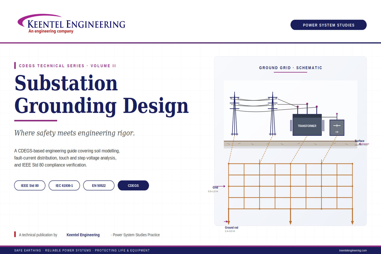
Learn substation grounding design using IEEE Std 80, CDEGS, soil resistivity modeling, touch and step voltage analysis, GPR, and earthing best practices.
By SANDIP R PATEL
•
July 29, 2026
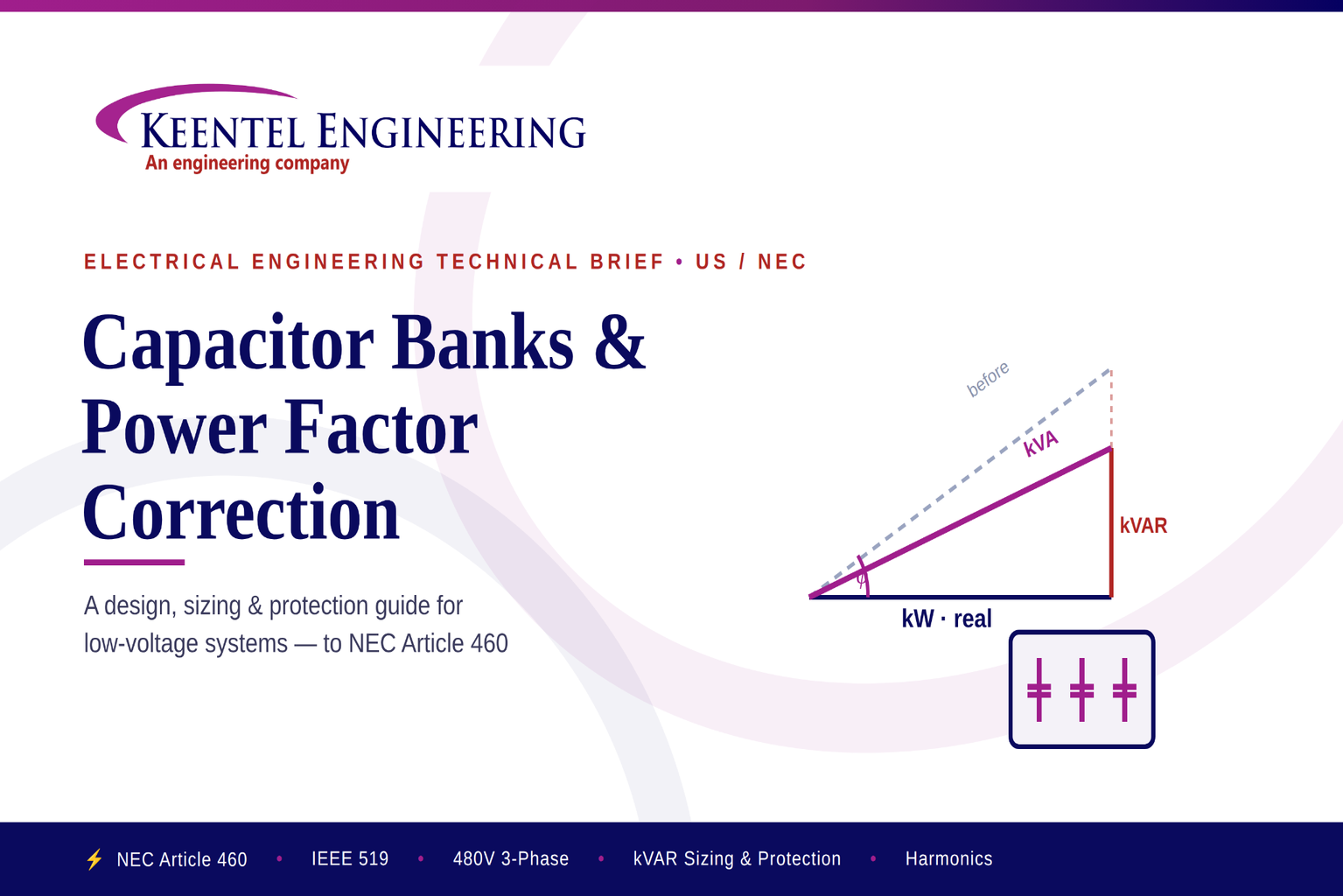
Learn capacitor bank sizing, power factor correction, NEC Article 460 requirements, harmonic mitigation, protection, and installation for industrial power systems.
By SANDIP R PATEL
•
July 29, 2026
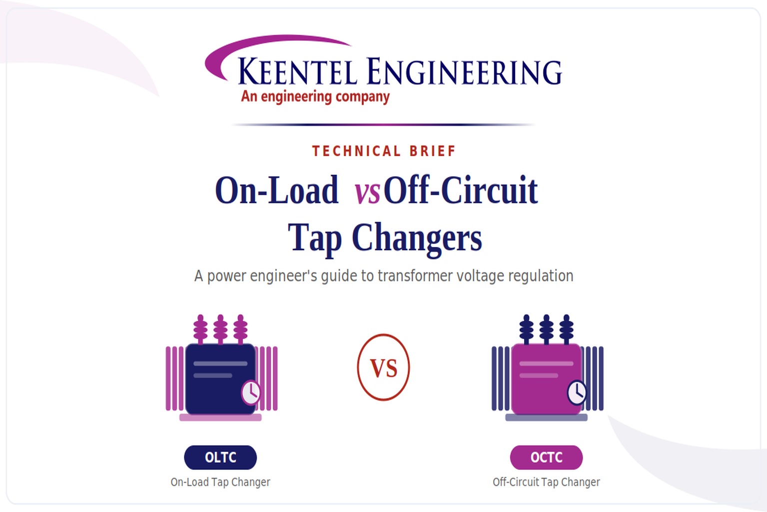
Learn the differences between On-Load and Off-Circuit Tap Changers, including OLTC vs OCTC operation, voltage regulation, IEEE standards, maintenance, and transformer selection.
By SANDIP R PATEL
•
July 28, 2026
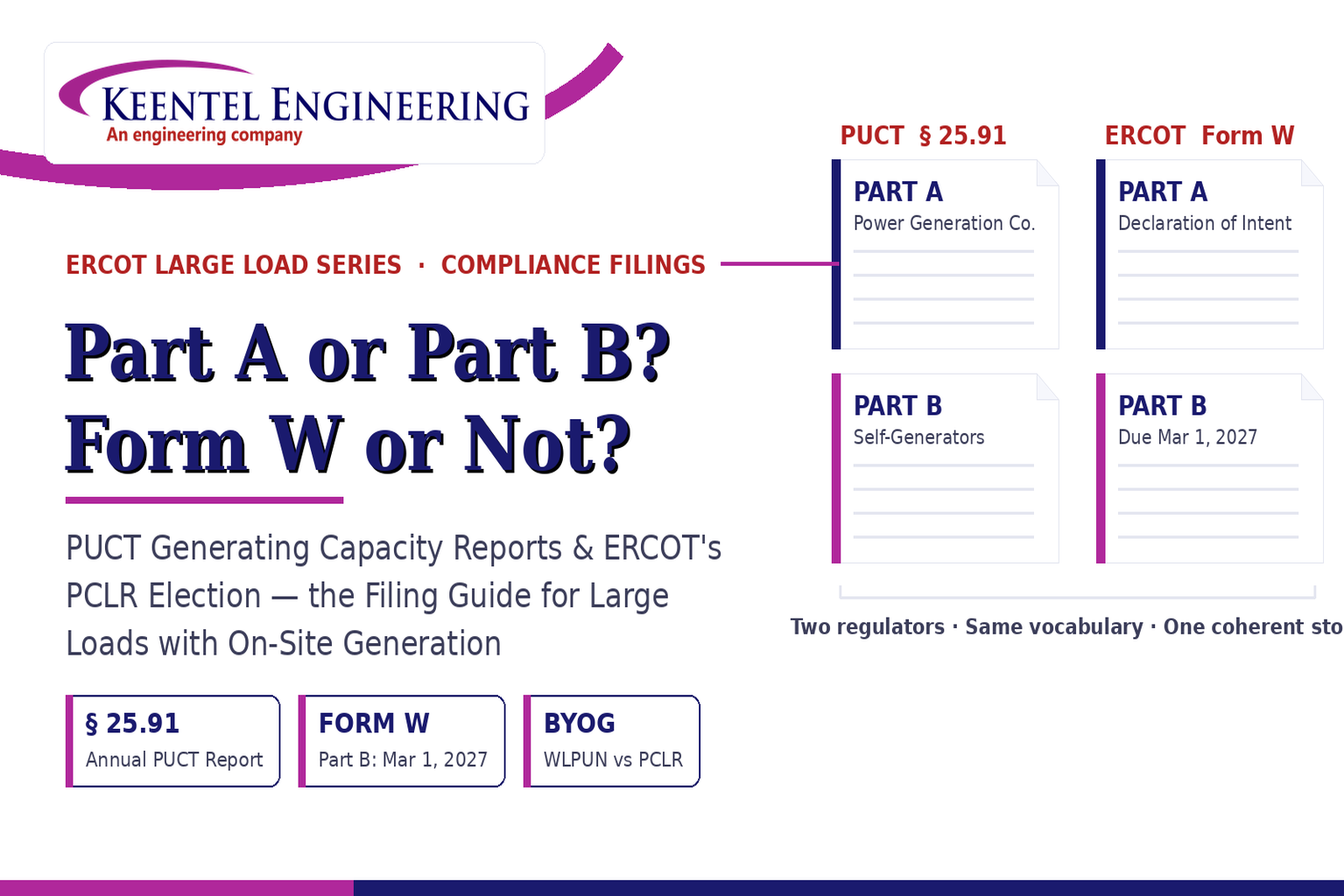
Learn the differences between the PUCT Generating Capacity Report and ERCOT Form W, including Part A vs Part B, PCLR, WLPUN, BYOG projects, and Batch Zero compliance.
By SANDIP R PATEL
•
July 28, 2026
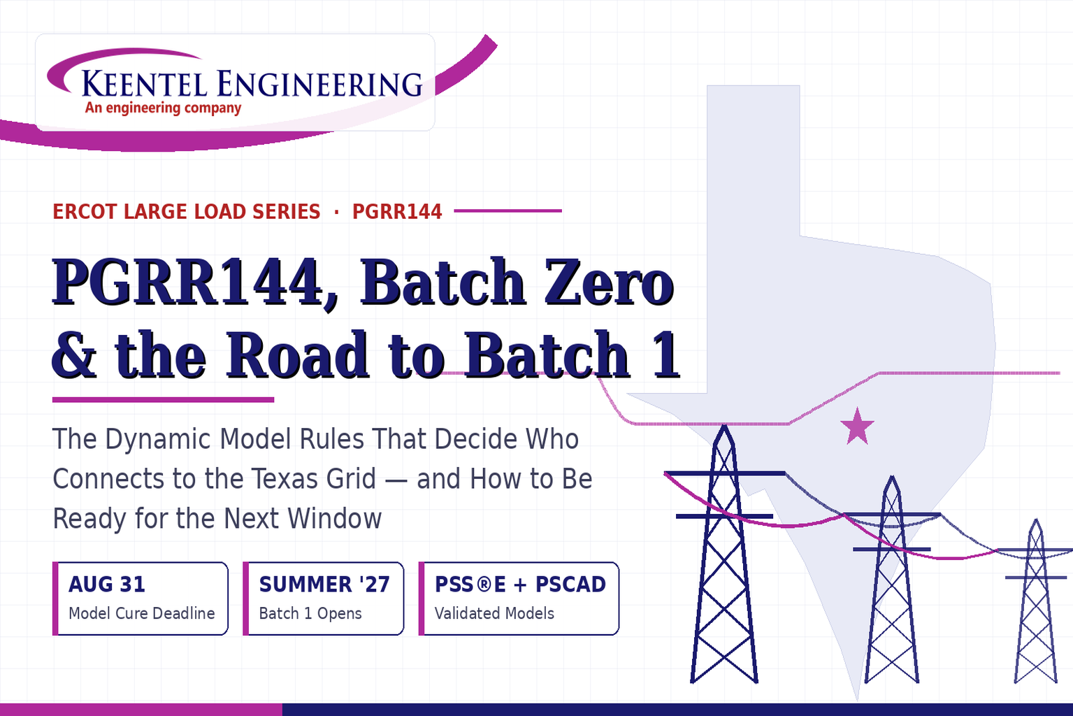
Learn how PGRR144, Batch Zero, and Batch 1 affect ERCOT large-load interconnections, dynamic model requirements, MQT testing, PERC1, and project readiness.
By SANDIP R PATEL
•
July 28, 2026
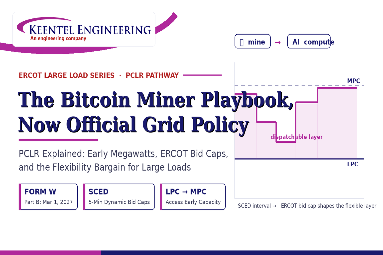
ERCOT PCLR Batch Zero large-load interconnection pathway
By SANDIP R PATEL
•
July 27, 2026
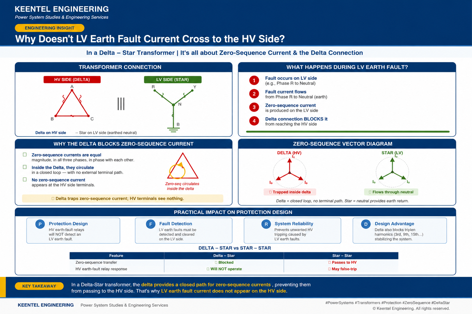
Learn why LV earth-fault current cannot cross a Delta-Star transformer, how zero-sequence current behaves, and what it means for protection design.

By SANDIP R PATEL
•
July 27, 2026
Learn how gas-insulated substations (GIS) improve safety, reliability, and space efficiency with 138 kV design, protection, insulation coordination, and real-world case studies.

By SANDIP R PATEL
•
July 25, 2026
Learn how Class I–IV electrical systems, defence-in-depth, standby and emergency power, DC systems, protection, and load transfer ensure nuclear power plant safety.